Download presentation
Presentation is loading. Please wait.

1
Subpart O - Machine Guarding
OTI 501 Paul Schlumper Welcome to Executive Introduction to ISO It will help us today if we have an idea of your expertise and experience. (Note count and write on flip chart) Please raise your hand if you have been closely involved in getting your company ISO 9000 registered or implementing and maintaining ISO 9000. Please raise your hand if you are the environmental manager or engineer or if you are involved with implementing environmental activities. Please raise your hand if you are the CEO or have management responsibility at your plant site. In the introduction we want to : (1)provide you with information on where you can get assistance and (2) provide you with a “road map to ISO 14000”, that is the big picture, before we get into the details.
 Please raise your hand if you have been closely involved in getting your company ISO 9000 registered or implementing and maintaining ISO Please raise your hand if you are the environmental manager or engineer or if you are involved with implementing environmental activities. Please raise your hand if you are the CEO or have management responsibility at your plant site. In the introduction we want to : (1)provide you with information on where you can get assistance and. (2) provide you with a road map to ISO , that is the big picture, before we get into the details.")
2
We Will Cover: Machine Guarding Principles Subpart O - Highlights Mock Plant Walk-Through

3
Why are machines not guarded?
No one would stick their arm, hand, finger, head, etc. in there. No one is supposed to be back there, in there, around it while it is running. The machine came that way; it never had a guard. I’ve been doing it this way for twenty years without any problems.

4
Why are machines not guarded? (cont.)
The guard is in the way The OSHA inspector didn’t say anything about it. We’ll put it back on if OSHA comes.

5
Emphasis on Amputations : Where does it apply?
General industry employers whose workplaces include: shears saws slicers slitters power presses (the 4s and a P)
")
6
Requirements for Safeguards
Prevent contact - prevent worker’s body or clothing from contacting hazardous moving parts Secure - firmly secured to machine and not easily removed Protect from falling objects - ensure that no objects can fall into moving parts Create no new hazards - must not have shear points, jagged edges or unfinished surfaces Create no interference - must not prevent worker from performing the job quickly and comfortably Allow safe lubrication - if possible, be able to lubricate the machine without removing the safeguards Prevent Contact - A good safeguarding system eliminates the possibility of the operator or other workers placing parts of their bodies near hazardous moving parts. Secure - A safeguard that can easily be made ineffective is no safeguard at all. Guards and safety devices should be made of durable material that will withstand the conditions of normal use and be firmly secured to the machine. Protect from falling objects - A small tool which is dropped into a cycling machine could easily become a projectile that could strike and injure someone. Create no new hazards - A safeguard defeats its own purpose if it creates a hazard of its own such as a shear point, a jagged edge, or an unfinished surface which can cause a laceration. The edges of guards, for instance, should be rolled or bolted in such a way that they eliminate sharp edges. Create no interference - Any safeguard which impedes a worker from performing a job quickly and comfortably might soon be overridden or disregarded. Proper safeguarding can actually enhance efficiency since it can relieve the worker’s apprehensions about injury. Allow safe lubrication - Locating oil reservoirs outside the guard, with a line leading to the lubrication point, will reduce the need for the worker to enter the hazardous area.

7
Where machine hazards occur:
Point of operation Mechanical power transmission Other moving parts

8
Machine Hazards

9
Machine Guarding

10
In-Running Nip Points Rotating cylinders Belt and pulley
Chain and sprocket Rack and pinion In-running nip point hazards are caused by the rotating parts on machinery. There are three main types of in-running nips. Parts can rotate in opposite directions while their axes are parallel to each other. These parts may be in contact (producing a nip point) or in close proximity to each other (where the stock fed between the rolls produces the nip points). This danger is common on machinery with intermeshing gears and rotating cylinders. Another type of nip point is created between rotating and tangentially moving parts; for example, a chain and a sprocket, a rack and pinion, or the point of contact between a power transmission belt and its pulley. Nip points can also occur between rotating and fixed parts which create a shearing, crushing, or abrading action; for example, spoked handwheels or flywheels, screw conveyors, or the periphery of an abrasive wheel and an incorrectly adjusted work rest.
 or in close proximity to each other (where the stock fed between the rolls produces the nip points). This danger is common on machinery with intermeshing gears and rotating cylinders. Another type of nip point is created between rotating and tangentially moving parts; for example, a chain and a sprocket, a rack and pinion, or the point of contact between a power transmission belt and its pulley. Nip points can also occur between rotating and fixed parts which create a shearing, crushing, or abrading action; for example, spoked handwheels or flywheels, screw conveyors, or the periphery of an abrasive wheel and an incorrectly adjusted work rest.")
11
Methods of machine safeguarding
Physical guards Devices Location/Distance

12
Methods of Machine Safeguarding
Guards fixed interlocked adjustable self-adjusting Devices presence sensing pullback restraint safety controls (tripwire cable, two-hand contol, etc.) gates Location/distance Feeding and ejection methods automatic and/or semi-automatic feed and ejection robots Miscellaneous aids awareness barriers protective shields hand-feeding tools
 gates. Location/distance. Feeding and ejection methods. automatic and/or semi-automatic feed and ejection. robots. Miscellaneous aids. awareness barriers. protective shields. hand-feeding tools.")
13
Guards Fixed Interlocked Adjustable Self-adjusting

16
Fixed Guard Provides a barrier - a permanent part of the machine, preferable to all other types of guards. (a)(2) As a general rule, power-transmission apparatus is best protected by fixed guards that enclose the danger area. For hazards at the point of operation, where moving parts actually perform work on stock, several kinds of safeguarding are possible.
(2) As a general rule, power-transmission apparatus is best protected by fixed guards that enclose the danger area. For hazards at the point of operation, where moving parts actually perform work on stock, several kinds of safeguarding are possible.")
17
Interlocked Guard When this type of guard is opened or removed, the tripping mechanism and/or power automatically shuts off or disengages, and the machine cannot cycle or be started until the guard is back in place. Interlocked guard on revolving drum An interlocked guard may use electrical, mechanical, hydraulic, or pneumatic power or any combination of these. Interlocks should not prevent “inching” by remote control, if required. Replacing the guard should not automatically restart the machine.

18
Adjustable Guard Provides a barrier which may be adjusted to facilitate a variety of production operations. Bandsaw blade adjustable guard Adjustable guards are useful because they allow flexibility in accommodating various sizes of stock, but, because they require adjusting, they are subject to human error.

19
Self-Adjusting Guard Provides a barrier which moves according to the size of the stock entering the danger area. Circular table saw self-adjusting guard Self-adjusting guards avoid the potential for human error associated with adjustable guards.

20
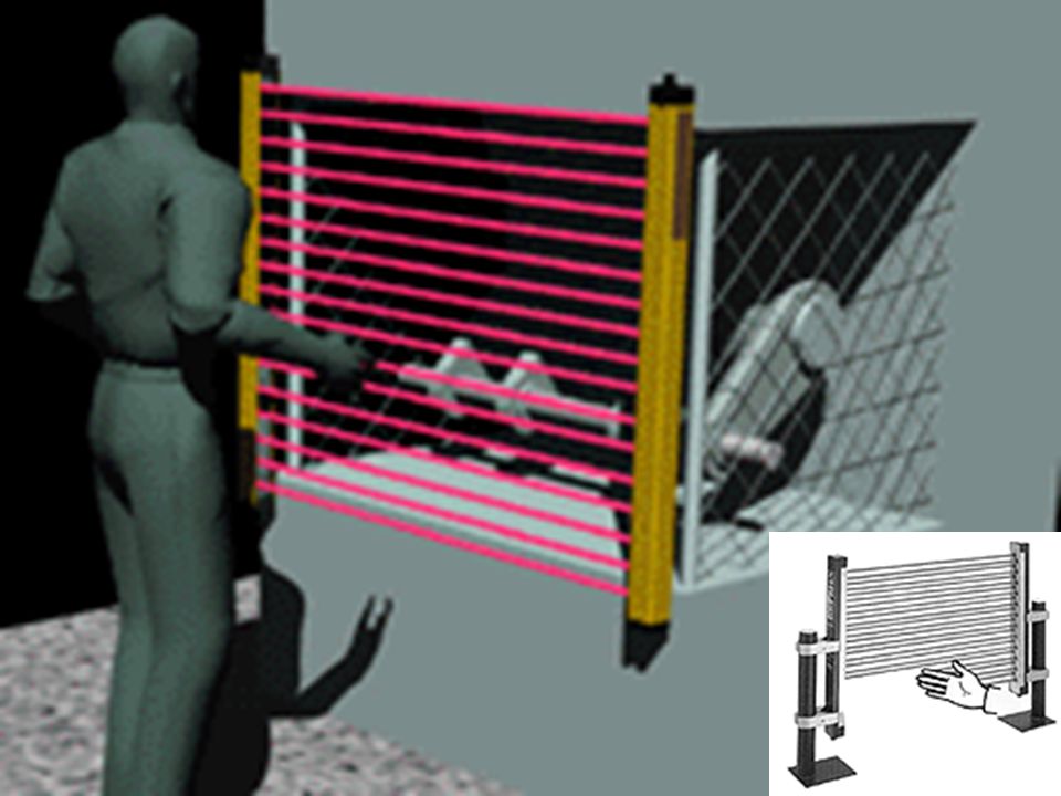
Safeguarding devices Presence sensing Pullback Restraint Safety controls and trips Gates

23
Pullback Device Utilizes a series of cables attached to the operator’s hands, wrists, and/or arms Primarily used on machines with stroking action Allows access to the point of operation when the slide/ram is up Withdraws hands when the slide/ram begins to descend

24
Pullback Device (cont’d)
Hands in die, feeding Point of operation exposed Pullback device attached and properly adjusted Die closed Hands withdrawn from point of operation by pullback device

25
Restraint Device Uses cables or straps attached to the operator’s hands and a fixed point Must be adjusted to let the operator’s hands travel within a predetermined safe area Hand-feeding tools are often necessary if the operation involves placing material into the danger area

26
Safety Tripwire Cables
Device located around the perimeter of or near the danger area Operator must be able to reach the cable to stop the machine Tripwire cables must be manually reset to restart the machine.

27
Two-Hand Control Requires constant, concurrent pressure to activate the machine The operator’s hands are required to be at a safe location (on control buttons) and at a safe distance from the danger area while the machine completes its closing cycle This kind of control requires a part-revolution clutch, brake, and brake monitor if used on a power press as shown. A similar device, known as a two-hand trip, requires concurrent application of both of the operator’s control buttons to activate the machine cycle, after which the hands are free. This device is used with machines equipped with full-revolution clutches. The trips must be placed far enough from the point of operation to make it impossible for the operators to move their hands from the trip buttons or handles into the point of operation before the first half of the cycle is completed to prevent them from being accidentally placed in the danger area prior to the slide/ram or blade reaching the full “down” position. .
 and at a safe distance from the danger area while the machine completes its closing cycle. This kind of control requires a part-revolution clutch, brake, and brake monitor if used on a power press as shown. A similar device, known as a two-hand trip, requires concurrent application of both of the operator’s control buttons to activate the machine cycle, after which the hands are free. This device is used with machines equipped with full-revolution clutches. The trips must be placed far enough from the point of operation to make it impossible for the operators to move their hands from the trip buttons or handles into the point of operation before the first half of the cycle is completed to prevent them from being accidentally placed in the danger area prior to the slide/ram or blade reaching the full down position. .")
28
Gate Movable barrier device which protects the operator at the point of operation before the machine cycle can be started If the gate does not fully close, machine will not function Another potential application of this type of device is where the gate is a component of a perimeter safeguarding system. Here the gate may provide protection not only to the operator but to pedestrian traffic as well. Gate Open Gate Closed

29
Safeguarding by Location/Distance
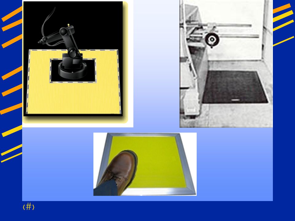
Locate the machine or its dangerous moving parts so that they are not accessible or do not present a hazard to a worker during normal operation Maintain a safe distance from the danger area One approach to safeguarding by location is shown in this photo. Operator controls may be located at a safe distance from the machine if there is no reason for the operator to tend it. Another approach is to locate the machine so that a plant design feature, such as a wall, protects the worker and other personnel. Enclosure walls or fences can also restrict access to machines. Another possible solution is to have dangerous parts located high enough to be out of the normal reach of any worker.

30
Automatic Feed (shown on power press)
Transparent Enclosure Guard Stock Feed Roll Danger Area Many feeding and ejection methods do not require operators to place their hands in the danger area. In some cases, no operator involvement is necessary after the machine is set up. In other situations, operators can manually feed the stock with the assistance of a feeding mechanism. Properly designed ejection methods do not require operator involvement after the machine starts to function. Using feeding and ejection methods does not eliminate the need for safeguarding. Guards and other devices must be used wherever they are necessary to provide protection from hazards. Automatic feeds reduce the operator exposure during the work process, and sometimes do not require any effort by the operator after the machine is set up and running. The power press shown in the photo above has an automatic feeding mechanism. Notice the transparent fixed enclosure guard at the danger area. Completed Work

31
Robots Machines that load and unload stock, assemble parts, transfer objects, or perform other tasks Best used in high-production processes requiring repeated routines where they prevent other hazards to employees Robots may create hazards themselves. If they do, appropriate guards must be used. The most common technique is to use perimeter guarding with interlocked gates. The American National Standards Institute (ANSI) safety standard for industrial robots, ANSI/RIA R , presents certain basic requirements for protecting the worker. However, when a robot is used in a workplace, the employer should accomplish a comprehensive operational safety and health hazard analysis and then implement an effective safeguarding system which is fully responsive to the situation. [Various effective safeguarding techniques are described in ANSI B (R1997).] Studies in Sweden and Japan indicate that many robot accidents did not occur under normal operating conditions, but rather during programming, program touch-up, maintenance, repair, testing, setup, or adjustment. During these operations, workers may temporarily be within the robot’s working envelope where unintended operation could result in injuries.
 safety standard for industrial robots, ANSI/RIA R , presents certain basic requirements for protecting the worker. However, when a robot is used in a workplace, the employer should accomplish a comprehensive operational safety and health hazard analysis and then implement an effective safeguarding system which is fully responsive to the situation. [Various effective safeguarding techniques are described in ANSI B (R1997).] Studies in Sweden and Japan indicate that many robot accidents did not occur under normal operating conditions, but rather during programming, program touch-up, maintenance, repair, testing, setup, or adjustment. During these operations, workers may temporarily be within the robot’s working envelope where unintended operation could result in injuries.")
32
Protective Shields These do not give complete protection from machine hazards, but do provide some protection from flying particles, splashing cutting oils, or coolants. Miscellaneous aids, such as these, do not give complete protection from machine hazards, but may provide the operator with an extra margin of safety.

33
Used to place and remove stock in the danger area
Holding Tools Used to place and remove stock in the danger area Not to be used instead of other machine safeguards, but as a supplement (a)(3)(iii)
(3)(iii)")
35
Subpart O - Machinery and Machine Guarding
211 - Definitions 212 - General requirements 213 - Woodworking machinery 215 - Abrasive wheel machinery 216 - Mills and calendars 217 - Mechanical power presses 218 - Forging machines 219 - Mechanical power transmission

36
General Requirements for all Machines
General Requirements for all Machines

37
(a)(1) One or more methods of machine guarding shall be provided to protect the operator and other employees in the machine area from hazards such as those created by the point of operation, in-going nip points, rotating parts, flying chips and sparks.

38
(a)(3)(ii) The point of operation of machines whose operation exposes an employee to injury, shall be guarded
(3)(ii) The point of operation of machines whose operation exposes an employee to injury, shall be guarded.")
39
(a)(5) When the periphery of the blades of a fan is less than seven (7) feet above the floor or working level, the blades shall be guarded. The guard shall have openings no larger than 1/2 inch.
 feet above the floor or working level, the blades shall be guarded. The guard shall have openings no larger than 1/2 inch.")
40
(b) Machines designed for a fixed location shall be securely anchored to prevent walking or moving.
 Machines designed for a fixed location shall be securely anchored to prevent walking or moving.")
41
Woodworking Machinery Requirements
Woodworking Machinery Requirements

42
(a)(9) All belts, pulleys, gears, shafts, and moving parts shall be guarded in accordance with the specific requirements of
(9) All belts, pulleys, gears, shafts, and moving parts shall be guarded in accordance with the specific requirements of")
43
(b)(1) A mechanical or electrical power control shall be provided on each machine to make it possible for the operator to cut off the power from each machine without leaving his position at the point of operation.

44
(b)(3) On applications where injury to the operator might result if motors were to restart after power failures, provision shall be made to prevent machines from automatically restarting upon restoration of power.

45
Table Saws

46
(c)(1) Each circular hand-fed ripsaw shall be guarded by a hood which shall completely enclose that portion of the saw above the table and that portion of the saw above the material being cut. The hood and mounting shall be arranged so that the hood will automatically adjust itself to the thickness of and remain in contact with the material being cut without considerable resistance.

47
(c)(2) Each hand-fed circular ripsaw shall be furnished with a spreader to prevent material from squeezing the saw or being thrown back on the operator.

48
(c)(3) Each hand-fed circular ripsaw shall be provided with non-kickback fingers or dogs so located as to oppose the thrust or tendency of the saw to pick up the material or throw it back toward the operator.

49
(d)(1) Each circular crosscut table saw shall be guarded by a hood which shall meet all the requirements of (c)(1) for hoods for circular resaws.
(1) for hoods for circular resaws.")
50
Radial Arm Saws

51
(i)(1) All portions of the saw blade (bandsaws) shall be enclosed or guarded, except for the working portion of the blade between the bottom of the guide rolls and the table.
 shall be enclosed or guarded, except for the working portion of the blade between the bottom of the guide rolls and the table.")
52
(r)(4) The mention of specific machines in paragraphs (a) thru (q) and this paragraph (r) of this section, inclusive, is not intended to exclude other woodworking machines from the requirements that suitable guards and exhaust hoods be provided to reduce to a minimum the hazard due to the point of operation of such machines.
 thru (q) and this paragraph (r) of this section, inclusive, is not intended to exclude other woodworking machines from the requirements that suitable guards and exhaust hoods be provided to reduce to a minimum the hazard due to the point of operation of such machines.")
53
(s)(7) All cracked saws shall be removed from service.
(7) All cracked saws shall be removed from service.")
54
Abrasive-Wheel Machinery
Abrasive-Wheel Machinery

55
(a)(4) Work rests shall be adjusted closely to the wheel with a maximum opening of one-eighth inch to prevent the work from being jammed between the wheel and the rest, which may cause wheel breakage.

56
(b)(9) The distance between the wheel periphery and the adjustable tongue or the end of the peripheral member at the top shall never exceed one-fourth inch.

57
(d)(1) Immediately before mounting, all wheels shall be closely inspected and sounded by the user (ring test) to make sure they have not been damaged.
 to make sure they have not been damaged.")
58
Abrasive Wheel Machinery
The distance between the wheel periphery and the adjustable tongue must never exceed 1/4-inch. (b)(9)
(9)")
59
Mechanical Power Presses
Mechanical Power Presses

60
(a)(5) Press brakes, hydraulic and pneumatic power presses, bulldozers, hot bending and hot metal presses, forging presses and hammers, riveting machines and similar types of fastener applicators are excluded from the requirements of this section.

61
(b)(4) The pedal mechanism shall be protected to prevent unintended operation. A pad with a nonslip contact area shall be firmly attached to the pedal.

62
(b)(6) A two-hand trip shall have the individual operator’s hand controls protected against unintended operation and be arranged to require use of both hands. Two-hand trip systems on full revolution clutch machines shall incorporate an antirepeat feature. If two hand trip systems are used on multiple operator systems, each operator shall have a separate set of controls.

63
(b)(7) Two-hand controls must incorporate an anti repeat feature, require use of both hands, be protected against unintended operation, have one set of controls for each operator. If foot control is provided, the selection between hand and foot control must be supervised by the employer.

64
(c)(1) It shall be the responsibility of the employer to provide and insure the use of point of operation guards or properly applied and adjusted point of operation devices on every operation performed on a mechanical power press. See Table O-10.

65
(e)(1) It shall be the responsibility of the employer to establish and follow a program of periodic and regular inspections of power presses.
(1) It shall be the responsibility of the employer to establish and follow a program of periodic and regular inspections of power presses.")
66
(e)(3) It shall be the responsibility of the employer to insure the original and continuing competence of personnel caring for, inspecting, and maintaining power presses.

67
Mechanical Power-Transmission Apparatus
Mechanical Power-Transmission Apparatus

68
(b)(1) Flywheels located so that any part is 7 feet or less above the floor or platform shall be guarded. Wherever flywheels are above working areas, guards shall be installed having sufficient strength to hold the weight of the flywheel in the event of a shaft or wheel mounting failure.

69
(c) Horizontal, vertical, and inclined shafting must be enclosed. Projecting shaft ends shall present a smooth edge and end and shall not project more than 1/2 the diameter of the shaft unless guarded by non rotating cap or safety sleeves.

70
(d) Pulleys 7ft. or less above the floor or platform must be guarded. Pulleys with cracks or pieces broken out of rims shall not be used.

71
Portable Power Tools - General Safety Precautions
Employers responsibility Safe condition of tools Including personal tools (b) Compressed air not used for cleaning except where reduced to less than 30 p.s.i. and only when effective chip guarding and PPE.
 Compressed air not used for cleaning except where reduced to less than 30 p.s.i. and only when effective chip guarding and PPE.")
72
Classification by power source
Power Tools Classification by power source Electric Pneumatic Liquid Fuel Hydraulic Powder Actuated

73
Power Tools (cont.) 1910.243 (a)(1) – Portable Circular Saws
Upper blade guard Lower blade guard Automatically returns to starting position

74
Power Tools (cont.) 1910.243(a)(2) Constant Pressure Switch
Saws and Chainsaws Lock-on control (single motion turnoff)
")
75
Pneumatic Power Tools and Hose
(b) Tool Retainer – A tool retainer must be installed on each piece of equipment where ejection could result Airhose – Hose and hose connections must be designed for the pressure and service to which they are subjected
 Tool Retainer – A tool retainer must be installed on each piece of equipment where ejection could result. Airhose – Hose and hose connections must be designed for the pressure and service to which they are subjected.")
76
Explosive Actuated Fastening Tools
Must meet requirements in ANSI A Operators and assistants must wear eye protection Head and face protection dependent on working conditions

77
Explosive Actuated Tools (Cont.)
Muzzle must have protective shield or guard at least 3 ½ inches in diameter. Firing must be dependent on at least 2 separate and distinct operations. Firing mechanism must prevent tool from firing during loading, while preparing, if dropped.

78
Explosive Actuated Tools (Cont.)
Tools must not be loaded until just before intended firing. Do not point at anyone! Fasteners not driven into hard/brittle or easily penetrable material Tools not used in hazardous atmosphere

79
Lawnmowers 243(e) Meet the requirements of ANSI B71.1-X1968
 Meet the requirements of ANSI B71.1-X1968")
Similar presentations


 Grants Chapter 6.>")


 Motion Controller Design for A Class of Second-order Systems Center for Self-Organizing Intelligent.>")


