Download presentation
Presentation is loading. Please wait.

1
Chapter 1: Distributed Information Systems

2
What is an Information System? Consists of: Hardware, Software, People, Networks, Processes, Data

3
What is IPC?(Information Processing Cycle) Converts data to information Consists of: Data Acquisition, Input, Data Validation, Data Processing, Data Storage, Data Retrieval, Output, Communication
 Converts data to information Consists of: Data Acquisition, Input, Data Validation, Data Processing, Data Storage, Data Retrieval, Output, Communication")
4
What is a Distributed System? Definition: A distributed system is one in which components located at networked computers communicate and coordinate their actions only by passing messages. This definition leads to the following characteristics of distributed systems: Concurrency of components Lack of a global ‘clock’ Independent failures of components 4

5
Distributed System Characteristics Multiple autonomous components Components are not shared by all users Resources may not be accessible Software runs in concurrent processes on different processors Multiple points of control Multiple points of failure 5

6
Examples of Distributed Systems Automatic Teller Machine Network Internet/World-Wide Web 6

7
Automatic Teller Machine Network 7

8
Internet 8

9
Contents Design of an information system – Layers and tiers – Top down design – Bottom up design Architecture of an information system – One tier – Two tier (Client/Server) – Three tier (Middleware) – N-tier architectures – Clusters and tier distribution Communication in an information system – Blocking or synchronous interactions – Non-blocking or asynchronous interactions
 – Three tier (Middleware) – N-tier architectures – Clusters and tier distribution Communication in an information system – Blocking or synchronous interactions – Non-blocking or asynchronous interactions")
10
Distributed Information System Web services are a form of Distributed Information Systems. Web services are the result of the natural evolution of Middleware and Enterprise Application integration platforms as they try to rely on Internet Technologies. In order to understand Web services, we need to understand how we got there and what is the relation of Web services with existing technologies to build distributed information systems. While the technology has changed, the problems that need to be solved are to a large extent the same. The aim of this lecture is to establish the correct perspective of Web services in the context of distributed information systems.

11
Layers of an Information System Information System PresentationLayer Resource Management Layer Application Logic Layer client

12
Presentation Layer Responsibilities of the presentation layer Communication with the external entities (both humans and systems). Information presentation. Interaction with other systems by accepting operations and getting responses. Presentation layer can take various forms Graphical User Interface (GUI). Module which formats a data set into a given syntactical representation. Should be distinguished from the notion of client Clients are consuming services provided by an information system (e.g., Web browser). Client and presentation layer may be merged into one (typical in Client/Server systems).
. Module which formats a data set into a given syntactical representation. Should be distinguished from the notion of client Clients are consuming services provided by an information system (e.g., Web browser). Client and presentation layer may be merged into one (typical in Client/Server systems)..")
13
Application Logic Layer Responsibilities of the application logic layer Data processing behind the delivered results. Implements actual operations submitted by clients through the presentation layer. The operations may be referred to as the services. Example of money transfer operation in a banking operation. Depending on the complexity of the logic involved and of the selected implementation technique we can refer to this layer as Business processes, Business rules, and Sometimes simply server.

14
Resource Management Layer Responsibilities of the resource management layer Data management (databases, file systems, other repositories) Implements different data sources of an information system independently of the nature of these data sources. Also known as data layer RML may include as a part any external system that provides information Other information systems with all three layers This allows for a recursive building of an information system

15
Top down designPresentationlayer resource management layer application logic layer client information system 1. define access channels and client platforms 2. define presentation formats and protocols for the selected clients and protocols 3. define the functionality necessary to deliver the contents and formats needed at the presentation layer 4. define the data sources and data organization needed to implement the application logic

16
Top-Down Design Typical workflow of top-down information system design: Starts from the functionality driven by clients and their interactions with the system. Application logic is developed to fulfill the required functionality. Supporting resources are defined to support application logic operations. Focuses first on the high-level goals of the problem and does everything to achieve the goals: Specifies, how the system will be distributed across different computing nodes. Usually created to run on homogeneous nodes, thus tightly coupled (components cannot be used independently). Advantages: Emphasizes the final system goals. Tailored to address functional (system operations) and non-functional (e.g., performance and availability) system properties. Drawbacks: Can be applied only to the systems developed from scratch (rarely a case today).
. Advantages: Emphasizes the final system goals. Tailored to address functional (system operations) and non-functional (e.g., performance and availability) system properties. Drawbacks: Can be applied only to the systems developed from scratch (rarely a case today)..")
17
Top down Architecture The functionality of a system is divided among several modules. Modules cannot act as a separate component, their functionality depends on the functionality of other modules. Hardware is typically homogeneous and the system is designed to be distributed from the beginning. top-down design PL-APL-B PL-C AL-A AL-B AL-D AL-C RM-1RM-2 top-down architecture RM-1RM-2 AL-A AL-D AL-C AL-B PL-A PL-B PL-C

18
Bottom up Design In a bottom up design, many of the basic components already exist. These are stand alone systems which need to be integrated into new systems. The components do not necessarily cease to work as stand alone components. Often old applications continue running at the same time as new applications. This approach has a wide application because the underlying systems already exist and cannot be easily replaced. Much of the work and products in this area are related to middleware, the intermediate layer used to provide a common interface, bridge heterogeneity, and cope with distribution. Legacy systems NewapplicationLegacyapplication

19
Bottom-up Design Typical workflow of bottom-up information system design Starting with the high-level goals as in the previous case. Evaluating RML to see whether something can be fulfilled What are the costs, feasibility to obtain the information RML components are wrapped to enable proper interfaces for app. logic layer Designing application logic. Occurs from necessity rather than choice Integration of existing systems (e.g., legacy apps). Everything is predefined and cannot be easily modified. How to integrate such a system in a coherent whole? Yields loosely-coupled systems by design Legacy systems are used as components and maintained as stand-alone systems No sense to talk about advantages/disadvantages Usually there is no other choice Web services are making bottom-up design more efficient, cost-effective, and simple.
. Everything is predefined and cannot be easily modified. How to integrate such a system in a coherent whole. Yields loosely-coupled systems by design Legacy systems are used as components and maintained as stand-alone systems No sense to talk about advantages/disadvantages Usually there is no other choice Web services are making bottom-up design more efficient, cost-effective, and simple..")
20
Bottom up Architecture bottom-up design PL-APL-B PL-C AL-A AL-B AL-D AL-C bottom-up architecture AL-A AL-D AL-C AL-B PL-A PL-B PL-Cwrapperwrapperwrapper wrapperwrapperwrapperlegacyapplicationlegacyapplication legacysystemlegacysystemlegacysystem

21
Bottom up Designpresentationlayer resource management layer application logic layer client information system 1. define access channels and client platforms 2. examine existing resources and the functionality they offer 3. wrap existing resources and integrate their functionality into a consistent interface 4. adapt the output of the application logic so that it can be used with the required access channels and client protocols bottom-up design

22
Three layers are logically separating functionality of an information system The layers may be combined and distributed in different ways Not anymore layers but TIERS. There exist 4 basic types of information systems depending on how tiers are organized: 1-tier, 2-tier, 3-tier, and N-tier. Architecture of an Information System

24
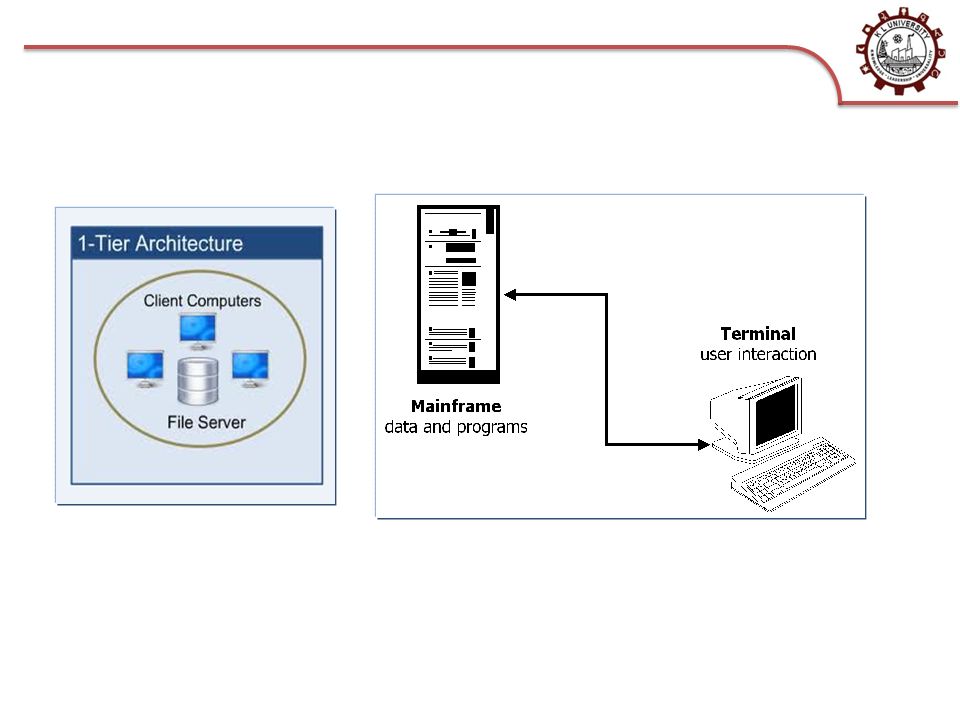
One tier: Fully Centralized Direct result of the computer architectures used several decades ago Mainframe-based systems, Interaction through dumb terminals (keyboard + computer screen) - clients, Efficient usage of CPU. They represent monolithic systems All layers are merged into the single tier Canonical example of legacy systems No entry-points from outside, No API provided to access the system functionality and resources, Most popular method of integration is screen-scraping (simulating user and parsing the screen outputs) – expensive, ad-hoc, not elegant, not efficient. 1-tier architecture Server PL AL RML
 – expensive, ad-hoc, not elegant, not efficient. 1-tier architecture Server PL AL RML.")
25
Advantages of 1-tier systems Merging of layers to optimize performance (use of low level languages, no context switching, no complex data transformations, no networking overhead). Zero client development, deployment and maintenance costs. Drawbacks of 1-tier systems Monolithic piece of code – difficult and expensive to maintain (lack of documentation and qualified programmers). Software industry is moving from them since many years Modern mainframe software is no more monolithic.. P2P networks of inexpensive small computers (PC) can provide equal power. One tier
. Software industry is moving from them since many years Modern mainframe software is no more monolithic.. P2P networks of inexpensive small computers (PC) can provide equal power. One tier.")
26
Two tier: Client/Server As computers became more powerful, it was possible to move the presentation layer to the client. This has several advantages: – Clients are independent of each other: one could have several presentation layers depending on what each client wants to do. – One can take advantage of the computing power at the client machine to have more sophisticated presentation layers. This also saves computer resources at the server machine. – It introduces the concept of API (Application Program Interface). An interface to invoke the system from the outside. It also allows designers to think about federating the systems into a single system. – The resource manager only sees one client: the application logic. This greatly helps with performance since there are no client connections/sessions to maintain. 2-tier architecture Server
. An interface to invoke the system from the outside. It also allows designers to think about federating the systems into a single system. – The resource manager only sees one client: the application logic. This greatly helps with performance since there are no client connections/sessions to maintain. 2-tier architecture Server.")
27
Two tierArchitecture

28
API in Client/Server Client/server systems introduced the notion of service (the client invokes a service implemented by the server) Together with the notion of service, client/server introduced the notion of service interface (how the client can invoke a given service) Taken all together, the interfaces to all the services provided by a server (whether there are application or system specific) define the server’s Application Program Interface (API) that describes how to interact with the server from the outside Many standardization efforts were triggered by the need to agree to common APIs for each type of server resource management layer server serviceinterfaceserviceinterfaceserviceinterfaceserviceinterface server’s API serviceserviceserviceservice
 Together with the notion of service, client/server introduced the notion of service interface (how the client can invoke a given service) Taken all together, the interfaces to all the services provided by a server (whether there are application or system specific) define the server’s Application Program Interface (API) that describes how to interact with the server from the outside Many standardization efforts were triggered by the need to agree to common APIs for each type of server resource management layer server serviceinterfaceserviceinterfaceserviceinterfaceserviceinterface server’s API serviceserviceserviceservice")
29
Two tier Came with the emergence of PC (i.e., inexpensive hardware) Presentation layer can be detached from the layers below and deployed on the cheaper and smaller machines Presentation layer can utilize the computational power available at PC, Presentation layer can be tailored for different purposes without increasing the complexity of the remaining system. The best example of two-tier architectures is client/server architecture Client – presentation layer. Server – application layer and resource management layer. Clients can be Thin – provide only a minimum of functionality, and Easier to port/install/maintain, require less processing capacity (wider range of computers) Thick – provide wide range of functionality More sophisticated, offer richer functionality, large footprint and use considerable resources.
 Thick – provide wide range of functionality More sophisticated, offer richer functionality, large footprint and use considerable resources..")
30
Two tier Client/server is associated with many key developments in software for distributed systems Remote Procedure Calls (RPC) [interaction between client and server] Application Programming Interface (API) stable published interfaces which can be used by clients. specify how to invoke a service, expected responses, effects on internal server state. C/S architectures became starting point for many crucial aspects of modern information systems Services – individual server programs responsible for app logics, Abstraction of service interface from the implementation, Standardization to address need for services (the last example are Web services).
![Two tier Client/server is associated with many key developments in software for distributed systems Remote Procedure Calls (RPC) [interaction between client and server] Application Programming Interface (API) stable published interfaces which can be used by clients.](http://images.slideplayer.com/39/10876504/slides/slide_30.jpg " specify how to invoke a service, expected responses, effects on internal server state. C/S architectures became starting point for many crucial aspects of modern information systems Services – individual server programs responsible for app logics, Abstraction of service interface from the implementation, Standardization to address need for services (the last example are Web services)..")
31
Two tier Advantages of two-tier architectures Key operations can be executed faster because ALL and RML are together. Portability through separated presentation layer. Provision of multiple presentation layers. Drawbacks of two-tier architectures Server issues Single server can serve only limited number of clients (connections, authentication, context maintenance, resources allocated to ALL and RML). Typically they are running on a less expensive machines – limited scalability. Client issues Clients cannot be easily made to connect to the different servers, They need to integrate different communication services Understanding of different APIs makes clients bigger and more complex, dependent on various systems which reduces their useful lifetime. Client is responsible for integration of two or more servers – extra app layer is embedded in client Ad-hoc procedure of customizing the client to a new server must be repeated from scratch for every possible combination of servers.
. Typically they are running on a less expensive machines – limited scalability. Client issues Clients cannot be easily made to connect to the different servers, They need to integrate different communication services Understanding of different APIs makes clients bigger and more complex, dependent on various systems which reduces their useful lifetime. Client is responsible for integration of two or more servers – extra app layer is embedded in client Ad-hoc procedure of customizing the client to a new server must be repeated from scratch for every possible combination of servers..")
32
Three tierArchitecture

33
Three tier Problems of two-tier architectures Proliferation of servers with stable and published interfaces. Creation of islands of information – clients can communicate only to the particular servers. LAN-based increase of network bandwidth. Opening a possibility to integrate different servers Three-tier architectures are a solution to this problem The additional layer between clients and servers is used for the integration of underlying systems – application logic supporting integration resides in it. Finally we have clear separation between each of the three layers Presentation layer resides at the client Application logic resides at the middle tier – MIDDLEWARE. Resource management layer is composed of all servers integrated by the 3- tier architecture. Each of these servers may have its own ALL and RML. Programs running on ALL are clients working in client/server setting.

34
Three tier Scalability advantages of 3-tier over 2-tier architectures In 2-tier architectures scalability is achieved by increasing the server power – very expensive. In 3-tier architectures scalability can be accomplished by running each layer in a different server Application logic can be distributed across several nodes; it is less tied to RML, more portable and reusable. Communication becomes much more expensive. Concepts introduced in 3-tier systems are: Clear interfaces of resource managers (e.g., ODBC and JDBC). Standardized interfaces for application logic code. Three-tier systems are targeted to be used for integration issues Middleware supporting services which can be used by application logic This created another standardization wave (X/Open for transactions, CORBA).
. Standardized interfaces for application logic code. Three-tier systems are targeted to be used for integration issues Middleware supporting services which can be used by application logic This created another standardization wave (X/Open for transactions, CORBA)..")
35
Three Tier Advantages of 3-tier architectures Additional tier where the integration logic resides. Performance loss is compensated by the flexibility provided by the additional tier and the logistics services. Distributing functionality across nodes – boosting scalability and reliability. Disadvantages of 3-tier architectures Legacy problems – when integration must happen between different 3-tier systems or over the Internet. They are not designed for inter-network integration neither have standards to bridge the gap between 3 tier systems.

36
A three tier middleware based system External clients connecting logic control user logic internal clients 2 tier systems Resource managers wrappers middleware Resource manager 2 tier system middleware system External client

37
N- tierArchitecture

38
N- Tier Applies the three-tier model to its full generality and takes into account the relevance of the Web as access channel. Resolves some problems of pure 3-tier systems Inter-system linking and integration. RML may include also full-fledged 2-tier and 3-tier systems. Connectivity over the Internet. Web servers as part of the presentation layer – an additional layer. The architecture of N-tier systems can be very complex with many different tiers They are build for future building. Disadvantages Too much middleware involved, often redundant functionality Difficulty and cost of developing, tuning, maintaining and evolving increases exponentially with the number of tiers. It may be difficult event to identify where the system begins and where it ends.

39
N-tier: connecting to the Web N-tier architectures result from connecting several three tier systems to each other and/or by adding an additional layer to allow clients to access the system through a Web server The Web layer was initially external to the system (a true additional layer); today, it is slowly being incorporated into a presentation layer that resides on the server side (part of the middleware infrastructure in a three tier system, or part of the server directly in a two tier system) The addition of the Web layer led to the notion of “application servers”, which was used to refer to middleware platforms supporting access through the Web client resource management layer application logic layer information system N-tierarchitecture middleware presentationlayer Web server Web browser HTML filter
; today, it is slowly being incorporated into a presentation layer that resides on the server side (part of the middleware infrastructure in a three tier system, or part of the server directly in a two tier system) The addition of the Web layer led to the notion of application servers , which was used to refer to middleware platforms supporting access through the Web client resource management layer application logic layer information system N-tierarchitecture middleware presentationlayer Web server Web browser HTML filter")
40
INTERNET FIREWALL LAN Webservercluster LAN,gateways LAN internalclients LAN middlewareapplicationlogic resourcemanagementlayer databaseserver LANmiddlewareapplicationlogic additional resource management layers LANWrappersandgatewaysfileserverapplication N-tier systems in reality

41
Synchronous or Blocking Calls

42
Blocking or synchronous interaction Traditionally, information systems use blocking calls (the client sends a request to a service and waits for a response of the service to come back before continuing doing its work) Synchronous interaction requires both parties to be “on-line”: the caller makes a request, the receiver gets the request, processes the request, sends a response, the caller receives the response. The caller must wait until the response comes back. The receiver does not need to exist at the time of the call (TP-Monitors, CORBA or DCOM create an instance of the service/server /object when called if it does not exist already) but the interaction requires both client and server to be “alive” at the same time Because it synchronizes client and server, this mode of operation has several disadvantages: – connection overhead – higher probability of failures – difficult to identify and react to failures – it is a one-to-one system; it is not really practical for nested calls and complex interactions (the problems becomes even more acute) Call Receive Response Answer idle time clientserver
 but the interaction requires both client and server to be alive at the same time Because it synchronizes client and server, this mode of operation has several disadvantages: – connection overhead – higher probability of failures – difficult to identify and react to failures – it is a one-to-one system; it is not really practical for nested calls and complex interactions (the problems becomes even more acute) Call Receive Response Answer idle time clientserver.")
43
Overhead of synchronism Synchronous invocations require to maintain a session between the caller and the receiver. Maintaining sessions is expensive and consumes CPU resources. There is also a limit on how many sessions can be active at the same time (thus limiting the number of concurrent clients connected to a server) For this reason, client/server systems often resort to connection pooling to optimize resource utilization – have a pool of open connections – associate a thread with each connection – allocate connections as needed Synchronous interaction requires a context for each call and a context management system for all incoming calls. The context needs to be passed around with each call as it identifies the session, the client, and the nature of the interaction. request() do with answer receiveprocessreturn sessionduration request() receiveprocessreturn Context is lost Needs to be restarted!!
 For this reason, client/server systems often resort to connection pooling to optimize resource utilization – have a pool of open connections – associate a thread with each connection – allocate connections as needed Synchronous interaction requires a context for each call and a context management system for all incoming calls. The context needs to be passed around with each call as it identifies the session, the client, and the nature of the interaction. request() do with answer receiveprocessreturn sessionduration request() receiveprocessreturn Context is lost Needs to be restarted!!.")
44
Failures in synchronous calls If the client or the server fail, the context is lost and resynchronization might be difficult. – If the failure occurred before 1, nothing has happened – If the failure occurs after 1 but before 2 (receiver crashes), then the request is lost – If the failure happens after 2 but before 3, side effects may cause inconsistencies – If the failure occurs after 3 but before 4, the response is lost but the action has been performed (do it again?) Who is responsible for finding out what happened? Finding out when the failure took place may not be easy. Worse still, if there is a chain of invocations (e.g., a client calls a server that calls another server) the failure can occur anywhere along the chain. request() do with answer receiveprocessreturn 1 2 34 request() timeout try again do with answer receiveprocessreturn 1 2 3 receiveprocessreturn 2’ 3’
, then the request is lost – If the failure happens after 2 but before 3, side effects may cause inconsistencies – If the failure occurs after 3 but before 4, the response is lost but the action has been performed (do it again ) Who is responsible for finding out what happened. Finding out when the failure took place may not be easy. Worse still, if there is a chain of invocations (e.g., a client calls a server that calls another server) the failure can occur anywhere along the chain. request() do with answer receiveprocessreturn request() timeout try again do with answer receiveprocessreturn receiveprocessreturn 2’ 3’.")
45
Two solutions ENHANCED SUPPORT Client/Server systems and middleware platforms provide a number of mechanisms to deal with the problems created by synchronous interaction: – Transactional interaction: to enforce exactly once execution semantics and enable more complex interactions with some execution guarantees – Service replication and load balancing: to prevent the service from becoming unavailable when there is a failure (however, the recovery at the client side is still a problem of the client) ASYNCHRONOUS INTERACTION Using asynchronous interaction, the caller sends a message that gets stored somewhere until the receiver reads it and sends a response. The response is sent in a similar manner Asynchronous interaction can take place in two forms: – non-blocking invocation (a service invocation but the call returns immediately without waiting for a response, similar to batch jobs) – persistent queues (the call and the response are actually persistently stored until they are accessed by the client and the server)
 – persistent queues (the call and the response are actually persistently stored until they are accessed by the client and the server).")
46
Disadvantages of synchronous calls Significant waste of time and resources. Significant waste of time and resources. Waiting process can be even swapped out of memory which increases even more the time to respond. Waiting process can be even swapped out of memory which increases even more the time to respond. Danger of running out of connections. Danger of running out of connections. Components are highly tied (coupled) which hinders distribution. Components are highly tied (coupled) which hinders distribution. Complex to use when there is many tiers involved. Complex to use when there is many tiers involved. It requires both the caller and the called to be present and online during the interaction time It requires both the caller and the called to be present and online during the interaction time Reduces fault tolerance. Makes maintenance procedures more complex (during the system upgrade everything goes down).
 which hinders distribution. Components are highly tied (coupled) which hinders distribution. Complex to use when there is many tiers involved. Complex to use when there is many tiers involved. It requires both the caller and the called to be present and online during the interaction time It requires both the caller and the called to be present and online during the interaction time Reduces fault tolerance. Makes maintenance procedures more complex (during the system upgrade everything goes down)..")
47
ASynchronous or Non-Blocking Calls

48
Asynchronous Communication calls The message is sent and then at some later time the program checks whether an answer has arrived. The message is sent and then at some later time the program checks whether an answer has arrived. – The caller is not blocked, it can do some other tasks thus saving time and resources. – No need to coordinate the interaction. It can be used as an underlying mechanism to support Remote Procedure Calls (RPC) under design constrains (e.g., limited number of connections opened). It can be used as an underlying mechanism to support Remote Procedure Calls (RPC) under design constrains (e.g., limited number of connections opened).
 under design constrains (e.g., limited number of connections opened). It can be used as an underlying mechanism to support Remote Procedure Calls (RPC) under design constrains (e.g., limited number of connections opened)..")
49
Advantage &Disadvantages of asynchronous calls Advantages Reduces problems with connection management, dependencies management, fault tolerance, format representation. Reduces problems with connection management, dependencies management, fault tolerance, format representation. Especially useful when the required communication pattern is not request/response by nature Especially useful when the required communication pattern is not request/response by nature Information dissemination. Event notification. Publish/subscribe solutions. Disadvantages Messages must be stored at some intermediate place Messages must be stored at some intermediate place But additional functionality can be added to it to promote them as full message brokers – Filtering and controlling message queue and flow of messages, – Implementing complex distribution strategies, – Manipulating format/content of the messages

50
Message Queuing Reliable queuing turned out to be a very good idea and an excellent complement to synchronous interactions: – Suitable to modular design: the code for making a request can be in a different module (even a different machine!) than the code for dealing with the response – It is easier to design sophisticated distribution modes (multicast, transfers, replication, coalescing messages) an it also helps to handle communication sessions in a more abstract way – More natural way to implement complex interactions between heterogeneous systems do with answer request()request() receiveprocessreturn queue queue
 than the code for dealing with the response – It is easier to design sophisticated distribution modes (multicast, transfers, replication, coalescing messages) an it also helps to handle communication sessions in a more abstract way – More natural way to implement complex interactions between heterogeneous systems do with answer request()request() receiveprocessreturn queue queue")
Similar presentations