Download presentation
Presentation is loading. Please wait.

1
Pusat Pengajian Kejuruteraan Mikroelektronik EMT 351/4 DIGITAL IC DESIGN Verilog Behavioural Modeling (Part 4) Week #
 Week #")
2
Contents Finite State Machine –Moore & Mealy Machine –State Encoding Techniques

3
Finite State Machine (FSM) Synchronous state machines are one of the most common building blocks in modern digital systems State machines operate at hardware speeds where software cannot compete Often engineers take an ad-hoc approach to design the state machine hence could arise poorly architecture and also glitches may appear in the outputs
 Synchronous state machines are one of the most common building blocks in modern digital systems State machines operate at hardware speeds where software cannot compete Often engineers take an ad-hoc approach to design the state machine hence could arise poorly architecture and also glitches may appear in the outputs")
4
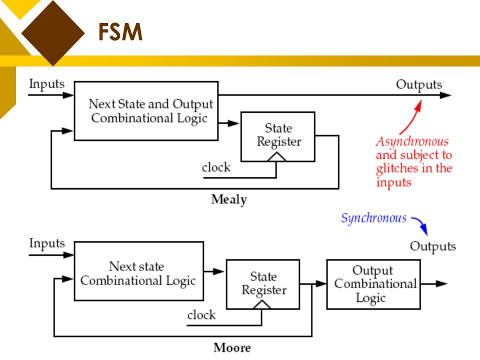
FSM could be divided into two types: –Moore Machine the outputs only depend on the current state –Mealy Machine the outputs depend on both the current state AND the input variables FSM

6
Moore State Machine The easiest of the two state machine types The outputs are combinatorial signals based solely on the current (present) state Unfortunately, this can lead to glitches on the output signals which can cause erratic (inconsistent) operation of circuitry driven by state machine
 state Unfortunately, this can lead to glitches on the output signals which can cause erratic (inconsistent) operation of circuitry driven by state machine")
7
State transition diagram (STD) of Moore machine 1 0 0 0 1 1 zero [0] one1 [0] two1s [1] output name of state input A Moore ‘’11’ sequence detector Moore State Machine
![State transition diagram (STD) of Moore machine zero [0] one1 [0] two1s [1] output name of state input A Moore ‘’11’ sequence detector Moore State Machine](http://images.slideplayer.com/39/10840427/slides/slide_7.jpg "State transition diagram (STD) of Moore machine zero [0] one1 [0] two1s [1] output name of state input A Moore ‘’11’ sequence detector Moore State Machine")
8
Mealy State Machine The outputs are a function of not only the current state, but also the inputs This implementation can lead to timing problems since the output timing is not simply a function of the clock, but of the input timing as well For this reason, the Mealy architecture is generally a poor choice for synchronous devices or designs

9
1/0 0/0 1/1 zero one1 State transition diagram of Mealy machine A Mealy ’11’ sequence detector output name of state input Mealy State Machine

10
Ease of design –Moore state machine is easier to design than Mealy. First design the states depending on the previous state and input. Then design output only depending on state. –Whereas in Mealy, you have to consider both state and input while designing the output Moore vs. Mealy

11
Number of states –Mealy state machine uses less states than the Moore. Since inputs influence the output in the immediate clock, memory needed to remember the input is less. So, it uses less flip-flops and hence circuit is simpler Moore vs. Mealy

12
Output / Response –In Mealy, output changes immediately when the input changes. So, Mealy is faster than Moore. Mealy gives immediate response to input and Moore gives response in the next clock Mealy vs. Moore

13
FSM Behavioural Model The logic in a state machine described using ‘case’ statement or ‘if-else’ statement All possible combinations of current state and inputs are enumerated (listed), and the appropriate values are specified for next state and the outputs
, and the appropriate values are specified for next state and the outputs")
14
There are 2 fundamental descriptive style of FSM –Explicit (used often) Declares a state register to encode the machine’s state –Implicit Uses multiple event controls (@) within a cyclic behavior to implicitly describe an evolution of states Only good for machines in which a given state can be reached from only one other state FSM Behavioural Model
 Declares a state register to encode the machine’s state –Implicit Uses multiple event controls within a cyclic behavior to implicitly describe an evolution of states Only good for machines in which a given state can be reached from only one other state FSM Behavioural Model")
15
Content of Verilog FSM Consist of –Continuous assignments that implements the next state logic –Continuous assignments that implements the output logic –Continuous cyclic (‘always’) behavior that updates the states
 behavior that updates the states")
16
Styles of FSM (1) module FSM_style1 (...) input...; output...; parameter size =...; reg [size-1 : 0] state, next_state; assign the_outputs =...// a function of state and // inputs assign next_state =... // a function of state and inputs. always @ (negedge reset or posedge clk) if (reset == 1’b0) state <= start_state; else state <= next_state;// non-blocking assignment endmodule
![Styles of FSM (1) module FSM_style1 (...) input...; output...; parameter size =...; reg [size-1 : 0] state, next_state; assign the_outputs =...// a function of state and // inputs assign next_state =...](http://images.slideplayer.com/39/10840427/slides/slide_16.jpg "// a function of state and inputs. (negedge reset or posedge clk) if (reset == 1’b0) state <= start_state; else state <= next_state;// non-blocking assignment endmodule.")
17
Styles of FSM (2) module FSM_style2 (...) input...; output...; parameter size =...; reg [size-1 : 0] state, next_state; assign the_outputs =... // a function of state and inputs always @ ( state or the_inputs ) begin // decode next_state with ‘case’ or ‘if’ statement end always @ (negedge reset or posedge clk) if (reset == 1’b0) state <= start_state; else state <= next_state; // Non-blocking or procedural // assignment endmodule Cyclic behaviour is used to declare the next-state logic
![Styles of FSM (2) module FSM_style2 (...) input...; output...; parameter size =...; reg [size-1 : 0] state, next_state; assign the_outputs =...](http://images.slideplayer.com/39/10840427/slides/slide_17.jpg "// a function of state and inputs ( state or the_inputs ) begin // decode next_state with ‘case’ or ‘if’ statement end (negedge reset or posedge clk) if (reset == 1’b0) state <= start_state; else state <= next_state; // Non-blocking or procedural // assignment endmodule Cyclic behaviour is used to declare the next-state logic.")
18
Styles of FSM (3) module FSM_style3 (...) input...; output...; parameter size =...; reg [size-1 : 0] state, next_state; always @ ( state or the_inputs ) begin // decode next_state with case or if statement end always @ (negedge reset or posedge clk) if (reset == 1’b0) state <= start_state; else begin state <= next_state; outputs <= some_value (inputs, next_state); end endmodule Declares output inside the cyclic block that updates the states
![Styles of FSM (3) module FSM_style3 (...) input...; output...; parameter size =...; reg [size-1 : 0] state, next_state; ( state or the_inputs ) begin // decode next_state with case or if statement end (negedge reset or posedge clk) if (reset == 1’b0) state <= start_state; else begin state <= next_state; outputs <= some_value (inputs, next_state); end endmodule Declares output inside the cyclic block that updates the states](http://images.slideplayer.com/39/10840427/slides/slide_18.jpg "Styles of FSM (3) module FSM_style3 (...) input...; output...; parameter size =...; reg [size-1 : 0] state, next_state; ( state or the_inputs ) begin // decode next_state with case or if statement end (negedge reset or posedge clk) if (reset == 1’b0) state <= start_state; else begin state <= next_state; outputs <= some_value (inputs, next_state); end endmodule Declares output inside the cyclic block that updates the states")
19
State Encoding Techniques Binary Encoding Assigns states by the minimum logic difference in the state transition graph. This normally reduces the amount of logic needed to decode each state. The minimum number of bits in the state register for an FSM with n states is log 2n 0001 1011

20
One Hot Encoding Its principle is to associate one code bit and also one flip-flop to each state. At a given clock cycle during operation, one and only state variable is asserted. Only two state variables toggle during a transition between two states. State Encoding Techniques 00010010 01001000

21
One Hot Encoding (cont..) One-hot encoding is very appropriate with most FPGA targets where a large number of flip-flops are available. It is also a good alternative when trying to optimize speed or to reduce power dissipation. State Encoding Techniques

22
Gray Code Encoding Gray encoding guarantees that only one state variable switches between two consecutive states. It is appropriate for controllers exhibiting long paths without branching. In addition, this coding technique minimizes hazards and glitches. Very good results can be obtained when implementing the state register with T flip-flops. State Encoding Techniques

23
BINARYGRAYONE-HOT B2B1B0B2B1B0 G2G1G0G2G1G0 O7O6O5O4O3O2O1O0O7O6O5O4O3O2O1O0 000 00000001 001 00000010 01001100000100 01101000001000 10011000010000 10111100100000 11010101000000 11110010000000 State Encoding Techniques

24
Example A Mealy Sequence Detector: Detects two successive 0's or 1's in serial bit stream

25
module seq_det_mealy_1exp (clock, reset, in_bit, out_bit); input clock, reset, in_bit; output out_bit; reg [2:0] state_reg, next_state; parameter start_state = 3'b000; parameterread_1_zero = 3'b001; parameterread_1_one = 3'b010; parameter read_2_zero = 3'b011; parameter read_2_one = 3'b100; always @ (posedge clock or posedge reset) if (reset == 1) state_reg <= start_state; else state_reg <= next_state; always @ (state_reg or in_bit) case (state_reg) start_state: if (in_bit == 0) next_state <= read_1_zero; else if (in_bit == 1) next_state <= read_1_one; else next_state <= start_state; read_1_zero: if (in_bit == 0) next_state <= read_2_zero; else if (in_bit == 1) next_state <= read_1_one; else next_state <= start_state;
![module seq_det_mealy_1exp (clock, reset, in_bit, out_bit); input clock, reset, in_bit; output out_bit; reg [2:0] state_reg, next_state; parameter start_state = 3 b000; parameterread_1_zero = 3 b001; parameterread_1_one = 3 b010; parameter read_2_zero = 3 b011; parameter read_2_one = 3 b100; (posedge clock or posedge reset) if (reset == 1) state_reg <= start_state; else state_reg <= next_state; (state_reg or in_bit) case (state_reg) start_state: if (in_bit == 0) next_state <= read_1_zero; else if (in_bit == 1) next_state <= read_1_one; else next_state <= start_state; read_1_zero: if (in_bit == 0) next_state <= read_2_zero; else if (in_bit == 1) next_state <= read_1_one; else next_state <= start_state;](http://images.slideplayer.com/39/10840427/slides/slide_25.jpg "module seq_det_mealy_1exp (clock, reset, in_bit, out_bit); input clock, reset, in_bit; output out_bit; reg [2:0] state_reg, next_state; parameter start_state = 3 b000; parameterread_1_zero = 3 b001; parameterread_1_one = 3 b010; parameter read_2_zero = 3 b011; parameter read_2_one = 3 b100; (posedge clock or posedge reset) if (reset == 1) state_reg <= start_state; else state_reg <= next_state; (state_reg or in_bit) case (state_reg) start_state: if (in_bit == 0) next_state <= read_1_zero; else if (in_bit == 1) next_state <= read_1_one; else next_state <= start_state; read_1_zero: if (in_bit == 0) next_state <= read_2_zero; else if (in_bit == 1) next_state <= read_1_one; else next_state <= start_state;")
26
read_2_zero: if (in_bit == 0) next_state <= read_2_zero; else if (in_bit == 1) next_state <= read_1_one; else next_state <= start_state; read_1_one: if (in_bit == 0) next_state <= read_1_zero; else if (in_bit == 1) next_state <= read_2_one; else next_state <= start_state; read_2_one: if (in_bit == 0) next_state <= read_1_zero; else if (in_bit == 1) next_state <= read_2_one; else next_state <= start_state; default: next_state <= start_state; endcase assign out_bit = (((state_reg == read_2_zero && in_bit == 0 )) || ((state_reg == read_2_one) && in_bit == 1)) ? 1 : 0; endmodule // written using style 2 Note: Output asserts after two consecutive matching inputs. Machine is a Mealy type.

27
Example B Write a Verilog code based on the state transition diagram shown above. More examples..

28
module seq1011( clk, rst, inp, outp); input clk, rst, inp; output outp; reg [1:0] state; reg outp; always @( posedge clk, posedge rst ) begin if( rst ) state <= 2'b00; else begin case( state ) 2'b00: begin if( inp ) state <= 2'b01; else state <= 2'b10; end 2'b01: begin if( inp ) state <= 2'b11; else state <= 2'b10; end
![module seq1011( clk, rst, inp, outp); input clk, rst, inp; output outp; reg [1:0] state; reg outp; posedge clk, posedge rst ) begin if( rst ) state <= 2 b00; else begin case( state ) 2 b00: begin if( inp ) state <= 2 b01; else state <= 2 b10; end 2 b01: begin if( inp ) state <= 2 b11; else state <= 2 b10; end](http://images.slideplayer.com/39/10840427/slides/slide_28.jpg "module seq1011( clk, rst, inp, outp); input clk, rst, inp; output outp; reg [1:0] state; reg outp; posedge clk, posedge rst ) begin if( rst ) state <= 2 b00; else begin case( state ) 2 b00: begin if( inp ) state <= 2 b01; else state <= 2 b10; end 2 b01: begin if( inp ) state <= 2 b11; else state <= 2 b10; end")
29
2'b10: begin if( inp ) state <= 2'b01; else state <= 2'b11; end 2'b11: begin if( inp ) state <= 2'b01; else state <= 2'b10; end endcase end always @(posedge clk or posedge rst) begin if( rst ) outp <= 0; else if( state == 2'b11 ) outp <= 1; else outp <= 0; end endmodule// FSM coding style 3
 state <= 2 b01; else state <= 2 b11; end 2 b11: begin if( inp ) state <= 2 b01; else state <= 2 b10; end endcase end clk or posedge rst) begin if( rst ) outp <= 0; else if( state == 2 b11 ) outp <= 1; else outp <= 0; end endmodule// FSM coding style 3")
30
Up-down Counter: ASM Chart Example C Another example..

31
module Up_Down_Explicit (count, up_dwn, clock, reset_); output [2:0] count; input [1:0] up_dwn; input clock, reset_; reg [2:0] count, next_count; always @ (negedge clock or negedge reset_) if (reset_ == 0) count = 3’b0; else count = next_count; always @ (count or up_dwn) begin case (count) 0: case (up_dwn) 0, 3: next_count = 0; 1: next_count = 1; 2: next_count = 3'b111; default next_count = 0; endcase Explicit FSM Up-down Counter
![module Up_Down_Explicit (count, up_dwn, clock, reset_); output [2:0] count; input [1:0] up_dwn; input clock, reset_; reg [2:0] count, next_count; (negedge clock or negedge reset_) if (reset_ == 0) count = 3’b0; else count = next_count; (count or up_dwn) begin case (count) 0: case (up_dwn) 0, 3: next_count = 0; 1: next_count = 1; 2: next_count = 3 b111; default next_count = 0; endcase Explicit FSM Up-down Counter](http://images.slideplayer.com/39/10840427/slides/slide_31.jpg "module Up_Down_Explicit (count, up_dwn, clock, reset_); output [2:0] count; input [1:0] up_dwn; input clock, reset_; reg [2:0] count, next_count; (negedge clock or negedge reset_) if (reset_ == 0) count = 3’b0; else count = next_count; (count or up_dwn) begin case (count) 0: case (up_dwn) 0, 3: next_count = 0; 1: next_count = 1; 2: next_count = 3 b111; default next_count = 0; endcase Explicit FSM Up-down Counter")
32
1: case (up_dwn) 0, 3: next_count = 1; 1: next_count = 2; 2: next_count = 0; default next_count = 1; endcase 2: case (up_dwn) 0, 3: next_count = 2; 1: next_count = 3; 2: next_count = 1; default next_count = 2; endcase 3: case (up_dwn) 0, 3: next_count = 3; 1: next_count = 4; 2: next_count = 2; default next_count = 3; endcase 4, 5, 6, 7: if (up_dwn == 0 || up_dwn == 3) next_count = count; else if (up_dwn == 1) next_count = count + 1; else if (up_dwn == 2) next_count = count –1; else count = 0; endcase end endmodule
 0, 3: next_count = 1; 1: next_count = 2; 2: next_count = 0; default next_count = 1; endcase 2: case (up_dwn) 0, 3: next_count = 2; 1: next_count = 3; 2: next_count = 1; default next_count = 2; endcase 3: case (up_dwn) 0, 3: next_count = 3; 1: next_count = 4; 2: next_count = 2; default next_count = 3; endcase 4, 5, 6, 7: if (up_dwn == 0 || up_dwn == 3) next_count = count; else if (up_dwn == 1) next_count = count + 1; else if (up_dwn == 2) next_count = count –1; else count = 0; endcase end endmodule")
33
module Up_Down_Implicit1 (count, up_dwn, clock, reset_); output [2:0] count; input [1:0] up_dwn; input clock, reset_; reg [2:0] count; always @ (negedge clock or negedge reset_) if (reset_ == 0) count = 3’b0; else if (up_dwn == 2’b00 || up_dwn == 2’b11) count = count; else if (up_dwn == 2’b01) count = count + 1; else if (up_dwn == 2’b10) count = count –1; endmodule Implicit FSM Up-down Counter END
![module Up_Down_Implicit1 (count, up_dwn, clock, reset_); output [2:0] count; input [1:0] up_dwn; input clock, reset_; reg [2:0] count; (negedge clock or negedge reset_) if (reset_ == 0) count = 3’b0; else if (up_dwn == 2’b00 || up_dwn == 2’b11) count = count; else if (up_dwn == 2’b01) count = count + 1; else if (up_dwn == 2’b10) count = count –1; endmodule Implicit FSM Up-down Counter END](http://images.slideplayer.com/39/10840427/slides/slide_33.jpg "module Up_Down_Implicit1 (count, up_dwn, clock, reset_); output [2:0] count; input [1:0] up_dwn; input clock, reset_; reg [2:0] count; (negedge clock or negedge reset_) if (reset_ == 0) count = 3’b0; else if (up_dwn == 2’b00 || up_dwn == 2’b11) count = count; else if (up_dwn == 2’b01) count = count + 1; else if (up_dwn == 2’b10) count = count –1; endmodule Implicit FSM Up-down Counter END")
Similar presentations


 and Flow Tables UNIT 1 : Modeling Module 1.4 : Modeling Sequential circuits.>")

 When the sequence of actions in your design depend on the state of sequential elements, a finite state machine (FSM) can be.>")


>")


