Download presentation
Presentation is loading. Please wait.

1
Hybrid Abutment

2
Step-by-step Hybrid Abutment

3
Fabrication

4
Block selection

5
Finishing

6
The attachment is cut from the basal using a diamond separating disc.
Finishing The incisal side of the attachment point is scratched with a diamond separating disc. The attachment is cut from the basal using a diamond separating disc.

7
Optimum fit of the ceramic structure on the Ti base
Finishing The ceramic structure is carefully placed on the Ti base to check the fit. Optimum fit of the ceramic structure on the Ti base

8
Finishing Important! Do not finish the shoulder of the ceramic structure to prevent negatively affecting the Ti base. Finish the emergence profile if required taking the fit to the gingiva and the minimum thickness (0.5mm) into account.
 into account.")
9
Finishing The shoulder of the ceramic structure must not be finished to prevent negatively affecting the Ti base.

10
Finishing Care should be taken when finishing the emergence profile to prevent affecting the fit to the gingiva. The attachment point to the block is smoothed out taking the shape of the emergence profile and the crown margin into account. Individual shape adjustments must not be performed, as this negatively affects the fit of the crown on the hybrid abutment.

11
Clinical Try-In

12
Cleaned, untreated ceramic structures
Optional Clinical try-in Cleaned, untreated ceramic structures The ceramic structure is placed on the Ti base and the relative position is marked.

13
The screw channel is sealed with a foam pellet.
Optional Clinical try-in The screw channel is sealed with a foam pellet. The Virtual cartridge is inserted in the dispenser. The mixing tip is screwed on and the Oral Tip is attached.

14
Clinical try-in Optional
Virtual Extra Light Body Fast Set is applied to the Ti base ... ... and directly on the ceramic structure.

15
Clinical try-in Optional
The Ti base is introduced into the ceramic structure. In doing so, the alignment of the two components is checked (rotation lock/marking). The components are firmly held in place for approx. 2:30 minutes until the Virtual Extra Light Body Fast Set has set. Excess Virtual Extra Light Body Fast Set is removed from the screw channel with an instrument, e.g. a scalpel.
. The components are firmly held in place for approx. 2:30 minutes until the Virtual Extra Light Body Fast Set has set. Excess Virtual Extra Light Body Fast Set is removed from the screw channel with an instrument, e.g. a scalpel.")
16
Prepared hybrid abutment or hybrid abutment crown
Optional Clinical try-in Excess Virtual Extra Light Body Fast Set material is removed from the screw channel with an instrument. Prepared hybrid abutment or hybrid abutment crown

17
Optional Clinical try-in

18
Clinical try-in Optional
The hybrid abutment is manually screwed in place with the dedicated screw. The geometry of the hybrid abutment (e.g. fit, gingival anaemia) is checked in relation to the gingival margin. If desired, the screw channel of the hybrid abutment can be sealed with a foam pellet.
 is checked in relation to the gingival margin. If desired, the screw channel of the hybrid abutment can be sealed with a foam pellet.")
19
Tip: The inner aspect of the crown can be isolated with glycerine gel.
Optional Clinical try-in Tip: The inner aspect of the crown can be isolated with glycerine gel. The crown is placed on the hybrid abutment intraorally to check and if necessary adjust the proximal contacts. Note: No occlusal functional inspection must be performed at this stage.

20
Clinical try-in Optional
Virtual Extra Light Body Fast Set is applied to the inner aspect of the crown. The crown is pressed onto the hybrid abutment using the fingers until the final position is reached. The crown is held in the final position until the Virtual material has set.

21
Excess Virtual material is removed.
Optional Clinical try-in Excess Virtual material is removed. The occlusion/articulation is checked and adjustments are made with suitable grinding instruments, if necessary

22
The hybrid abutment is unscrewed.
Optional Clinical try-in The crown is carefully lifted from the hybrid abutment and the Virtual Extra Light Body Fast Set material is removed. The hybrid abutment is unscrewed.

23
Completing the Abutment

24
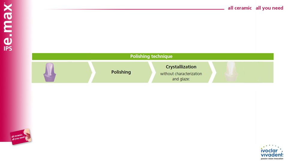
Options Polishing technique - Polishing of the "blue" restoration, followed by crystallization without individual characterization and glaze. Staining technique on the "blue" restoration - Characterization and glaze with IPS e.max CAD Crystall./ materials on the blue restoration, followed by Combination firing (Crystallization and Characterization/Glaze firing in one step). Staining technique on the tooth-colored restoration - Crystallization without the application of materials. Characterization/Glaze firing of the tooth-coloured restorations with either IPS e.max CAD Crystall./ or IPS e.max Ceram materials.
. Staining technique on the tooth-colored restoration - Crystallization without the application of materials. Characterization/Glaze firing of the tooth-coloured restorations with either IPS e.max CAD Crystall./ or IPS e.max Ceram materials.")
27
Polishing technique If no characterizations and no Glaze firing are desired, it is possible to polish the ceramic structure manually, followed by crystallization. Please note that polishing causes slight abrasion. The polishing technique is preferably used for the emergence profile of the hybrid abutment.

28
Polishing technique Pre-polishing by means of diamond rubber polishers
Fine polishing by means of high-gloss rubber polishers

29
Polishing technique High-gloss polishing with brushes and polishing paste Residue is removed with ultrasound in a water bath…

30
Polishing technique ...or with the steam jet.

31
Polishing technique - crystallization

32
Polishing technique - crystallization
The interface of the ceramic structure is slightly overfilled with IPS Object Fix Putty or Flow. Then the ceramic structure is placed in the center on the IPS e.max CAD Crystallization Tray. The crystallization tray is removed from the furnace once the crystallization program has been completed and the object is allowed to cool

33
Polishing technique - crystallization
The ceramic structure is removed from the IPS e.max CAD Crystallization Tray. Residue is removed with ultrasound in a water bath….

34
Polishing technique - crystallization
… or with the steam jet. Residue must not be removed with Al2O3 or glass polishing beads

35
Polishing technique - crystallization
Polished, crystallized ceramic structure

37
Staining technique on the "blue restoration"
If hybrid abutments are fabricated, only the area of the emergence profile is characterized with IPS e.max CAD Crystall./Shades, Stains and Glaze.

38
Staining technique on the "blue restoration"

39
Staining technique on the "blue restoration"
The IPS e.max CAD Crystallization Pin XS is used for the crystallization of the ceramic structure. The interface of the ceramic structure is filled with either IPS Object Fix Putty or Flow auxiliary firing paste.

40
Staining technique on the "blue restoration"
Important: – The IPS e.max CAD Crystallization Pin XS should be pressed only slightly into the IPS Object Fix Putty/Flow so that it does not touch the walls of the ceramic structure. Incorrect: Pin pressed in too deep. Pin touches the ceramic structure, which may lead to cracks.

41
Staining technique on the "blue restoration"
Displaced auxiliary firing paste is smoothed out with a plastic spatula from the margin towards the support pin so that the pin is secured in the paste. Any possible residue adhering to the outer surface/occlusal surface is cleaned off with a brush dampened with water and dried.

42
Staining technique on the "blue restoration"

43
Staining technique on the "blue restoration"

44
Staining technique on the "blue restoration"
IPS e.max CAD Crystall./Glaze Paste is extruded from the syringe and mixed. If required, the paste can be thinned withIPS e.max CADCrystall./Glaze Liquid. IPS e.max CAD Crystall./Glaze Paste is applied evenly on the emergence profile of the hybrid abutment.

45
Staining technique on the "blue restoration"
Important: The glazing material must reach neither the bonding surface to the Ti base nor the screw channel, as this may compromise the accuracy of fit.

46
Staining technique on the "blue restoration"
Individual characterizations of the emergence profile are applied using IPS e.max CAD Crystall./Shades. Enhancing the chroma

47
Staining technique on the "blue restoration"
IPS e.max CAD Crystall./Shade Incisal is applied to imitate the incisal area. Optional: For minor shape adjustments (e.g. proximal contact points), IPS e.max CAD Crystall./Add-On is available.
, IPS e.max CAD Crystall./Add-On is available.")
48
Staining technique on the "blue restoration"
The ceramic structure is placed in the centre of the IPS e.max CAD Crystallization Tray. The Combination firing is conducted using the stipulated firing parameters. The firing parameters for IPS e.max CAD MO and IPS e.max CAD LT must be observed. The ceramic structure is removed from the furnace after completion of the firing cycle (wait for the acoustic signal of the furnace).
.")
49
Staining technique on the "blue restoration"

50
Staining technique on the "blue restoration"
The ceramic structure is removed from the IPS e.max CAD Crystallization Pin XS. Residue is removed with ultrasound in a water bath….

51
Staining technique on the "blue restoration"
… or with the steam jet. Residue must not be removed with Al2O3 or glass polishing beads

52
Staining technique on the "blue restoration"
Glazed and characterized ceramic structure (hybrid abutment)
")
53
Staining technique on the "blue restoration"

54
Staining technique on the "blue restoration"
xxx xxx

55
Staining technique on the "tooth-colored" restoration
The IPS e.max CAD Crystallization Pin XS should be used for the crystallization of the ceramic structure The interface of the ceramic structure is filled with either IPS Object Fix Putty or Flow auxiliary firing paste.

56
Staining technique on the "tooth-colored" restoration
Important: – The IPS e.max CAD Crystallization Pin XS is only slightly pressed into the IPS Object Fix Putty/Flow so that it does not touch the walls of the ceramic structure. Incorrect: Pin pressed in too deep. Pin touches the ceramic structure. This may lead to cracks in the ceramic structure.

57
Staining technique on the "tooth-colored" restoration
Displaced auxiliary firing paste is smoothed out with a plastic spatula from the margin towards the support pin so that the pin is secured in the paste. Any possible residue adhering to the outer surface is cleaned off with a brush dampened with water and dried.

58
Staining technique on the "tooth-colored" restoration
Conduct the crystallization using the stipulated firing parameters. The firing parameters for IPS e.max CAD MO and IPS e.max CAD LT must be observed. Crystallized ceramic structure

59
Staining technique on the "tooth-colored" restoration

60
Staining technique on the "tooth-colored" restoration
If hybrid abutments are fabricated, only the area of the emergence profile is characterized with IPS e.max CAD Crystall./Shades, Stains and Glaze.

61
Staining technique on the "tooth-colored" restoration

62
Staining technique on the "tooth-colored" restoration
IPS e.max CAD Crystall./Glaze Paste is extruded from the syringe and mixed. If required, the paste is thinned with IPS e.max CADCrystall./Glaze Liquid. IPS e.max CAD Crystall./Glaze Paste is applied evenly on the emergence profile of the hybrid abutment.

63
Staining technique on the "tooth-colored" restoration
Important: The glazing material must reach neither the bonding surface to the Ti base nor the screw channel or the bonding surface to the crown, as this may compromise the accuracy of fit. Characterizing the emergence profile with Shades

64
Staining technique on the "tooth-colored" restoration
The Corrective firing is conducted on the IPS e.max CAD Crystallization Tray using the stipulated firing parameters.

65
Staining technique on the "tooth-colored" restoration

66
Staining technique on the "tooth-colored" restoration
The ceramic structure is removed from the IPS e.max CAD Crystallization Pin XS. Any residue is removed with ultrasound in a water bath or with the steam jet.

67
Staining technique on the "tooth-colored" restoration
Residue must not be removed with Al2O3 or glass polishing beads. Glazed and characterized ceramic structures (hybrid abutment)
")
68
Staining technique on the "tooth-colored" restoration
IPS e.max Ceram…

69
Staining technique on the "tooth-colored" restoration

70
Staining technique on the "tooth-colored" restoration
If hybrid abutments are fabricated, only the area of the emergence profile is characterized with IPS e.max Ceram Shades, Essences and Glaze.

71
Staining technique on the "tooth-colored" restoration
IPS e.max Ceram Shade Incisal is applied to imitate the incisal area.

72
Staining technique on the "tooth-colored" restoration
The Stain and Characterization firing is conducted on a honey-comb firing tray.

73
Staining technique on the "tooth-colored" restoration
Glaze firing Glaze firing is conducted with powder or paste glaze. On abutments, only the emergence profile is glazed. Required materials IPS e.max Ceram Glaze Paste, Glaze Powder are glazing materials in paste and powder forms. IPS e.max Ceram Glaze and Stain Liquid (allround, longlife) to mix the materials in powder form (Essences, Glaze), as well as to thin paste materials (Shades, Glaze)
 to mix the materials in powder form (Essences, Glaze), as well as to thin paste materials (Shades, Glaze)")
74
Staining technique on the "tooth-colored" restoration

75
Staining technique on the "tooth-colored" restoration
An even layer of glaze material is applied to the emergence profile of the hybrid abutment. Care has to be taken that no glaze material enters the screw channel.

76
Staining technique on the "tooth-colored" restoration
Care has to be taken that no glaze material is present on the interface of the hybrid abutment and hybrid abutment crown prior to the firing cycle. Characterization/Glaze firing is conducted on a honey-comb firing tray

77
IPS e.max CAD Hybrid Abutment

78
Staining technique on the "tooth-colored" restoration

79
Cementation

80
Hybrid Abutment

81
Cementation

82
Cementation

83
Preparation of the Ti base
The Ti base is screwed on the model analog. The relative position to the ceramic structure is marked with a waterproof pen. E.g. silicone (Virtual Extra Light Body Fast Set) is applied in order to protect the emergence profile and the screw channel.
 is applied in order to protect the emergence profile and the screw channel.")
84
Preparation of the Ti base
The bonding surface can be carefully blasted according to the instructions of the manufacturer. Removal of the silicone and subsequently cleaning with ultrasound in a water bath or with the steam jet.

85
Preparation of the Ti base
Monobond Plus is applied to the clean bonding surface and allowed to react for 60 s. After the reaction time, any remaining residue is dried with blown air that is free of water and oil. The screw channel is sealed with a foam pellet or wax. The bonding surface must not be contaminated in the process.

86
Preparation of the Ti base
The ceramic structure must not be blasted.. Etching with IPS Ceramic Etching Gel for 20 seconds. Subsequently, the restoration is rinsed with water and blown dry. Monobond Plus is allowed to react for 60 s, and excess is blown dry.

87
Cementation with Multilink® Hybrid Abutment
The cleaned and conditioned components are laid out ready for cementation. A new mixing tips is attached to the Multilink Hybrid Abutment prior to each use. The Multilink Hybrid Abutment mixing syringe is attached.

88
Cementation with Multilink® Hybrid Abutment
A thin layer of Multilink Hybrid Abutment is directly applied from the mixing tip to the bonding surface of the Ti base. A thin layer of Multilink Hybrid Abutment is directly applied from the mixing tip on the bonding surface of the ceramic structure.

89
Cementation with Multilink® Hybrid Abutment
5 s The ceramic structure is placed on the Ti base in such a way that the position markings are aligned. The components are joined using even and light pressure and the relative position of the components is checked (transition base/ceramic structure). Subsequently, the components are tightly pressed together for 5 s.
. Subsequently, the components are tightly pressed together for 5 s.")
90
Cementation with Multilink® Hybrid Abutment
2-3 min Excess in the screw channel is carefully removed, e.g. with a Microbrush or brush, using rotary movements. Important: Excess must not be removed before curing has started, i.e. 2–3 minutes after mixing. The components are held in place with light pressure in the process.

91
Cementation with Multilink® Hybrid Abutment
7 min Glycerine gel (e.g. Liquid Strip) is applied on the cementation joint to prevent the formation of an inhibition layer. The luting composite auto-polymerizes within 7 min. Important: The components must not be moved until auto-polymerization is completed. The components must be immobilized during this time.
 is applied on the cementation joint to prevent the. formation of an inhibition layer. The luting composite auto-polymerizes within 7 min. Important: The components must not be moved until auto-polymerization is completed. The components must be immobilized during this time.")
92
Cementation with Multilink® Hybrid Abutment
After the completion of auto-polymerization, the glycerine gel is rinsed off with water. The cementation joint is cautiously polished with rubber polishers at low speed (< 5,000 rpm), to avoid overheating.
, to avoid overheating.")
93
Cementation with Multilink® Hybrid Abutment
Any remaining cement residue in the screw channel is removed with suitable rotating instruments. The Ti base must not be damaged. Completed hybrid abutment after cementation

94
Seating and Aftercare The IPS e.max CAD ceramic structures must not be
blasted in preparation for cementation. The bonding surfaces are etched with IPS Ceramic Etching Gel and subsequently cleaned. Monbond Plus is applied to the bonding surfaces, and allowed to react for 60 s. Excess is dispersed with air.

95
Seating the hybrid abutment and dedicated crown

96
Seating The hybrid abutment is inserted into the implant intraorally.
The matching implant screw is screwed in manually.

97
Seating The implant screw is tightened with a
torque wrench (the instructions of the manufacturer must be observed). The screw channel is sealed, for instance with a cotton or foam pellet and a temporary composite material.
. The screw channel is sealed, for instance with a cotton or foam pellet. and a temporary composite material.")
98
The crown is placed on the hybrid abutment and secured in place.
Seating The luting material, e.g. SpeedCEM, is applied into the conditioned crown. The crown is placed on the hybrid abutment and secured in place.

99
Seating Pre-polymerization using the four-quarter technique
Excess luting material is removed.

100
Seating The restoration margin is covered with glycerine gel (e.g. Liquid Strip). The luting material is cured with an LED curing light (e.g. Bluephase).
.")
101
Seating The glycerine gel is rinsed off with water.
The occlusion and articulation is checked and adjustments are made, if necessary.

102
Completed IPS e.max CAD hybrid abutment and crown
Seating The restoration margins and the cementation joint are polished (e.g. OptraPol, OptraFine). Completed IPS e.max CAD hybrid abutment and crown
. Completed IPS e.max CAD hybrid abutment and crown.")
103
Hybrid Abutment

Similar presentations


 Arcadia Cleaning Soak the tube for 60 minutes in warm.>")


 2013 Mechanical Kits Ltd.1.>")
