Download presentation
Presentation is loading. Please wait.

1
Unit 18 Reflection & Refraction of Light

2
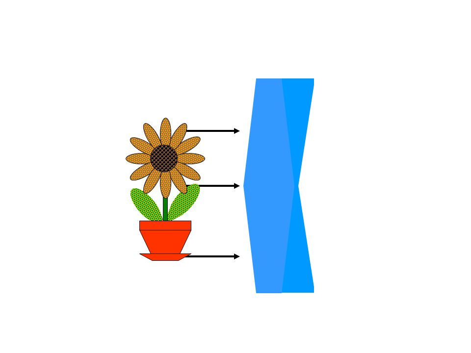
“Fun House” Mirrors

3
Types of Curved Mirrors There are two major types of mirrors based on whether they curve in or out. Concave Mirrors bend inward and are bowl-shaped. Convex Mirrors bend outward and are dome-shaped. Concave MirrorConvex Mirror

4
Reflection Observe the reflection of a laser beam due to the mirror. The Normal is an imaginary line drawn at a 90 angle with the surface of the mirror at the point where the beam strikes the mirror. The angle between the incident ray and the normal is known as the angle of incidence ( i ). The angle between the reflected ray and the normal is known as the angle of reflection ( r ). Mirror Incident RayReflected Ray Normal
. The angle between the reflected ray and the normal is known as the angle of reflection ( r ). Mirror Incident RayReflected Ray Normal.")
5
Mirror Types There are three types of mirrors: plane mirror, concave mirror, and convex mirror. Each of these three mirror types form images with different properties. A plane mirror forms an image that is the same size as the object. A convex mirror forms an image that is smaller than the object. A concave mirror forms an image that is larger than the object. What type of mirror is shown in the figure to the right? Convex Mirror 18-2 ?????Mirror Type????? ObjectReflected Image

6
Mirror Types What type of mirror is shown in the figure below? Plane Mirror. 18-3 ?????Mirror Type????? ObjectReflected Image

7
Mirror Types What type of mirror is shown in the figure below? Concave Mirror. 18-4 ?????Mirror Type????? ObjectReflected Image

8
Diffuse Scattering. Imagine that several parallel laser beams are fired at a mirror and a ceiling tile. The reflected beams from the mirror surface would still be parallel, and i and r would be equal. However, the reflected beams from the tile surface would not be parallel. The reflected beams from the tile surface exhibit diffuse scattering. 18-5 Mirror Ceiling Tile

9
Sound Wave Reflection The picture to the right shows the TV room of a disappointed viewer. He is very disappointed due to the poor sound quality of his TV. The rays represent the path the sound travels in the room. Sound waves, like light waves, reflect off of surfaces. He is sitting in an acoustic “dead zone.” Such a zone is typically the result of destructive interference of sound waves. What could he do in order to improve the sound quality? If he moves his chair, then he will be able to better hear and enjoy his TV. 18-6

10
Simply put, “Refraction” means bends. When discussing light beams, light bends when it goes from one medium (glass, water, air, etc.) to another. If it goes from a more dense medium to a less dense medium, then light speeds up and bends away from the Normal. If it goes from a less dense medium to a more dense medium, then light slows down and bends towards the Normal. Consider the wheel and axel to the right. It rolled from pavement (less dense) to gravel (more dense) The left wheel slowed down causing the axel to turn towards the normal. 18-7 Pavement Gravel Refraction
 to another. If it goes from a more dense medium to a less dense medium, then light speeds up and bends away from the Normal. If it goes from a less dense medium to a more dense medium, then light slows down and bends towards the Normal. Consider the wheel and axel to the right. It rolled from pavement (less dense) to gravel (more dense) The left wheel slowed down causing the axel to turn towards the normal Pavement Gravel Refraction.")
11
When light undergoes refraction while traveling from a less dense to a more dense medium, the light bends towards the normal. This is because light travels faster in a less dense medium than in a more dense medium. Is the fish safe from the laser if we point the laser at the fish? When laser light travels from air, a less dense medium, and is shined onto the surface of water, a more dense medium, in an fish tank, the light bends towards the normal as shown. As a result, the light will bend and travel below the fish. This bending of light at the interface of two mediums is known as refraction. 18-8 Normal

12
Refraction Refraction applies to Lenses as well. Which laser path to the right would the laser beam follow? When the beam first strikes the lens, it goes from a less dense to a more dense medium. As a result, the beam will slow down and turn towards the normal. When the beam strikes the boundary from the lens back to air, it goes from a more dense to a less dense medium. As a result, the beam speeds up and will turn away from the normal. It will stay on the same side of the normal. Therefore, the center beam path would be the correct path followed by the laser beam. 18-9

13
Refraction Which of the three paths (A, B, or C) is the one the beam would actually travel? Remember, lights bends towards the normal when it goes from a less dense to a more dense medium because it slows down in the more dense medium. Conversely, light bends away from the normal when it goes from a more dense to a less dense medium because it speeds up in the less dense medium. Which is the correct path? A B C Air Glass Water 18-11

14
Light Spectrum Previously, we learned that light travels in waves known as “Transverse” waves. Light is composed of massless particles known as photons. The spectrum of electromagnetic radiation spans several wavelengths (frequencies) of the photons. Of particular interest to us is the visible spectrum. To remember the visible spectrum, use the name “ROY G BIV.” VisibleInfraredUltra VioletGammaRadio WavesMicrowavesX-rays Red Orange Yellow Green Blue Indigo Violet Frequency Increases Speed Increases 18-12
 of the photons. Of particular interest to us is the visible spectrum. To remember the visible spectrum, use the name ROY G BIV. VisibleInfraredUltra VioletGammaRadio WavesMicrowavesX-rays Red Orange Yellow Green Blue Indigo Violet Frequency Increases Speed Increases")
15
Dispersion of Light Dispersion is the separation of light according to its frequencies into its different colors. A prism is a device often used to demonstrate dispersion of white light. Light with higher frequency travels slower in a medium; therefore, it will bend more with respect to the normal. Light with lower frequency travels faster; therefore, it will bend less with respect to the normal. One of the exit beams is orange and the other is green. Based on the above information, which exit beam is orange? Top or bottom? Red Orange Yellow Green Blue Indigo Violet Frequency Speed 18-13

16
Refraction & Fishing Dr. Physics is watching a fish swimming in a pond. He sees the fish indicated in the position shown. Which position, top or bottom, is the actual position of the fish? Why? When light beams travel from a more less to a more dense medium, they slows down and bend towards from the normal. As a result, the actual position of the fish is deeper than the apparent position of the fish. 18-14

17
Formation of Images by Spherical Mirrors We use ray diagrams to determine where an image will be. For mirrors, we use three key rays, all of which begin on the object: A ray parallel to the axis will be reflected through the focal point A ray through the focal point will be reflected parallel to the axis A ray perpendicular to the mirror will be reflected back on itself

18
cf Concave: Object outside of C Image is: Inverted Smaller Between C & F Real

19
c f Concave: Object is at C Image is: Inverted Same size At C Real

20
cf Concave: Object is between C & F Image is: Inverted Larger Outside of C Real

21
c f Concave: Inside of f Image is: Up right Larger Behind the mirror virtual

22
c f Convex: Image is: Up right Smaller Behind the mirror virtual

23
23.3 Formation of Images by Spherical Mirrors Geometrically, we can derive an equation that relates the object distance, image distance, and focal length of the mirror: (23-2)
")
24
cf Concave: Object is at f

25
1)Calculate the image location for an object which is 17cm from a concave mirror with a center of curvature of 24cm. 2)Calculate the image location for an object which is 43cm from a concave mirror with a center of curvature of 21cm. 3)Calculate the image location for an object which is 24cm from a concave mirror with a center of curvature of 24cm.
Calculate the image location for an object which is 43cm from a concave mirror with a center of curvature of 21cm. 3)Calculate the image location for an object which is 24cm from a concave mirror with a center of curvature of 24cm..")
26
23.3 Formation of Images by Spherical Mirrors We can also find the magnification (ratio of image height to object height). (23-3) The negative sign indicates that the image is inverted.
 The negative sign indicates that the image is inverted..")
27
Internal Reflection Suppose we had a laser submerged in water. If it was pointing straight up, then the beam would pass through the boundary interface without reflecting or refracting. If we rotate the laser, then some of the beam will reflect and some will refract. As we continue to rotate the laser, we would eventually observe the refracted beam traveling along the boundary interface. This phenomena occurs at the critical angle. As the laser is rotated past the critical angle, all of the beam will be reflected and none will be refracted. This phenomena is known as total internal reflection. 18-17

28
Lenses and Magnification – Diverging Lens When the beam first strikes the lens, it goes from a less dense to a more dense medium. As a result, the beam will slow down and turn towards the normal. When the beam strikes the boundary from the lens back to air, it goes from a more dense to a less dense medium. As a result, the beam speeds up and will turn away from the normal. Will the resulting image be larger or smaller than the original image? A diverging lens produces a larger image. 18-15

29
Lenses and Magnification – Converging Lens When the beam first strikes the lens, it goes from a less dense to a more dense medium. As a result, the beam will slow down and turn towards the normal. When the beam strikes the boundary from the lens back to air, it goes from a more dense to a less dense medium. As a result, the beam speeds up and will turn away from the normal. Will the resulting image be larger or smaller than the original image? A converging lens produces a smaller image. 18-16

30
Lens Vocabulary A – Center of Curvature B – Focal Point C – Focal Length D – Principal Axis AABB CC D 18-18

31
18-19 Magnification Magnification is the enlargement or reduction of the size of the image of an object produced by a lens. If the object is beyond twice the focal length (2f), then the image will be smaller and real (upside down) If the object is at 2f, the it will be the same size and real. Between f and 2f, the object will be larger and real. At f the image will focus at infinity (not be visible). In between f and the lens, the image will be much larger, virtual (right side up), and will appear on the same side of the lens as the object. This situation occurs with a magnifying glass.
, then the image will be smaller and real (upside down) If the object is at 2f, the it will be the same size and real. Between f and 2f, the object will be larger and real. At f the image will focus at infinity (not be visible). In between f and the lens, the image will be much larger, virtual (right side up), and will appear on the same side of the lens as the object. This situation occurs with a magnifying glass..")
32
The Anatomy of an Eye Label the following eye anatomy (parts) in the figure below. A – Cornea B – Lens C – Iris D – Blind Spot A B C D 18-20

33
Nearsighted A nearsighted person sees objects nearby clearly; however, far away objects appear blurry. The light rays from far away objects form the image within the eye before the rays reach the retina. This problem is corrected using a diverging lens. This diverging lens separates the rays before they reach the eye lens. The eye lens then focuses these rays on the retina thereby producing a high quality image. 18-21

34
Farsighted A farsighted person sees objects far away clearly; however, near objects appear blurry. The light rays from near objects would form the image beyond the eye in the brain cavity well beyond the retina. This result, of course, is impossible. This problem is corrected using a converging lens. This converging lens brings the rays together before they reach the eye lens. The eye lens then focuses these rays on the retina thereby producing a high quality image. 18-22

35
Index of Refraction, n The index of refraction is a ratio of the speed of light in a vacuum (c) to the speed of light in a medium (v) like glass, oil, water, quartz, diamond,…. The top figure shows a laser aimed into a evacuated cylinder (nothing is inside it). The speed of light in this cylinder is c = 3 x 10 8 m/s. The bottom figure shows a laser aimed into a cylinder of water. The light will travel slower in this cylinder, and its speed (v) can be measured in a lab. The ratio of these speeds gives the index of refraction (n) of the material through which the light is shined (in this case water). 1
. The speed of light in this cylinder is c = 3 x 10 8 m/s. The bottom figure shows a laser aimed into a cylinder of water. The light will travel slower in this cylinder, and its speed (v) can be measured in a lab. The ratio of these speeds gives the index of refraction (n) of the material through which the light is shined (in this case water). 1.")
36
Snell’s Law Snell’s law allows us to determine the angle of refraction given the angle of incidence of a light ray on a boundary interface. n 1 is the index of refraction of medium 1, and 1 is the angle of incidence on the boundary between the two interfaces. n 2 is the index of refraction of medium 2, and 2 is the angle of refraction. Based upon the picture to the right, which medium us more dense: 1 or 2? Why? Since the beam bent towards the normal when going from medium 1 to medium 2, medium 2 is more dense than medium 1. n 1 sin 1 = n 2 sin 2 n1n1 n2n2 18-23

37
Snell’s Law Given the following information, determine the type of surrounding material and the lens material. i = 65 R, Use N 1, n S = 1.36, n L = 1.54. Begin by measuring the incident angle and drawing the incident beam. Use Snell’s Law to calculate the refracted angle. Draw the refracted beam to the next material interface. Draw the normal as shown and measure the new incident angle. This step not shown. Use Snell’s Law to calculate the refracted angle, and draw the refracted beam. The material is determined based upon where your second refracted beam stops. What are your materials for this problem? Air with diamond lens Air with window glass lens Water with diamond lens Ethanol with Quartz lens N1N1 N2N2 N3N3 18-24 Assignment: 1. i = 65 R, Use N 1, n S = 1.36, n L = 1.54. 2. i = 45 R, Use N 2, n S = 1.33, n L = 2.42. 3. i = 30 L, Use N 3, n S = 1.00, n L = 1.61. 4. i = 30 L, Use N 3, n S = 1.00, n L = 2.42.

38
Snell’s Law Air: n 1 = 1.003 Diamond: n 2 = 2.42 1 = 60 Snell’s Law n 1 sin 1 = n 2 sin 2 60 21 9 22

39
Snell’s Law Water: n 1 = 1.33 Glass: n 2 = 1.52 1 = 40 Snell’s Law n 1 sin 1 = n 2 sin 2 40 34 26 62 18-26

40
Refraction Refraction is responsible for the “broken straw” effect you observe when viewing a straw in a drinking glass. In the next slide, we will use this effect in order to determine the index of refraction of glass. 18-27

41
Lab – Determination of n i for Glass Follow the procedure on your lab in order to find the index of refraction for the piece of glass provided by your instructor. You will do this experiment twice using different angles. P3P3 P2P2 P1P1 N1N1 N2N2 11 22 P4P4 22 11 18-28

42
This presentation was brought to you by Where we are committed to Excellence In Mathematics And Science Educational Services.

43
A AA 18-1

44
A AA N3N3 Air with window glass lens N1N1 N2N2 Glass around diamond lens Water around Quartz lens

45
A AA 18-1 N3N3 Air with window glass lens N1N1 N2N2 Glass around diamond lens Water around Quartz lens

46
A AA 18-1

47
A Keep Me 18-1 Air with diamond lens Air with window glass lens Water with diamond lens N1N1 N2N2 N3N3 Ethanol with Quartz lens

Similar presentations


:>")


