Download presentation
Presentation is loading. Please wait.

1
WAVES Optics

2
WAVE BEHAVIOR 3: DIFFRACTION
Diffraction is the bending of a wave AROUND a barrier Diffracted waves can interfere and cause “diffraction patterns”

3
DOUBLE SLIT DIFFRACTION
n = d sinΘ n: bright band number : wavelength (m) d: space between slits (m) Θ: angle defined by central band, slit, and band n This also works for diffraction gratings consisting of many, many slits that allow the light to pass through. Each slit acts as a separate light source
 d: space between slits (m) Θ: angle defined by central band, slit, and band n. This also works for diffraction gratings consisting of many, many slits that allow the light to pass through. Each slit acts as a separate light source.")
4
SINGLE SLIT DIFFRACTION
n = s sin Θ n: dark band number : wavelength (m) s: slit width (m) Θ: angle defined by central band, slit, and dark band
 s: slit width (m) Θ: angle defined by central band, slit, and dark band.")
5
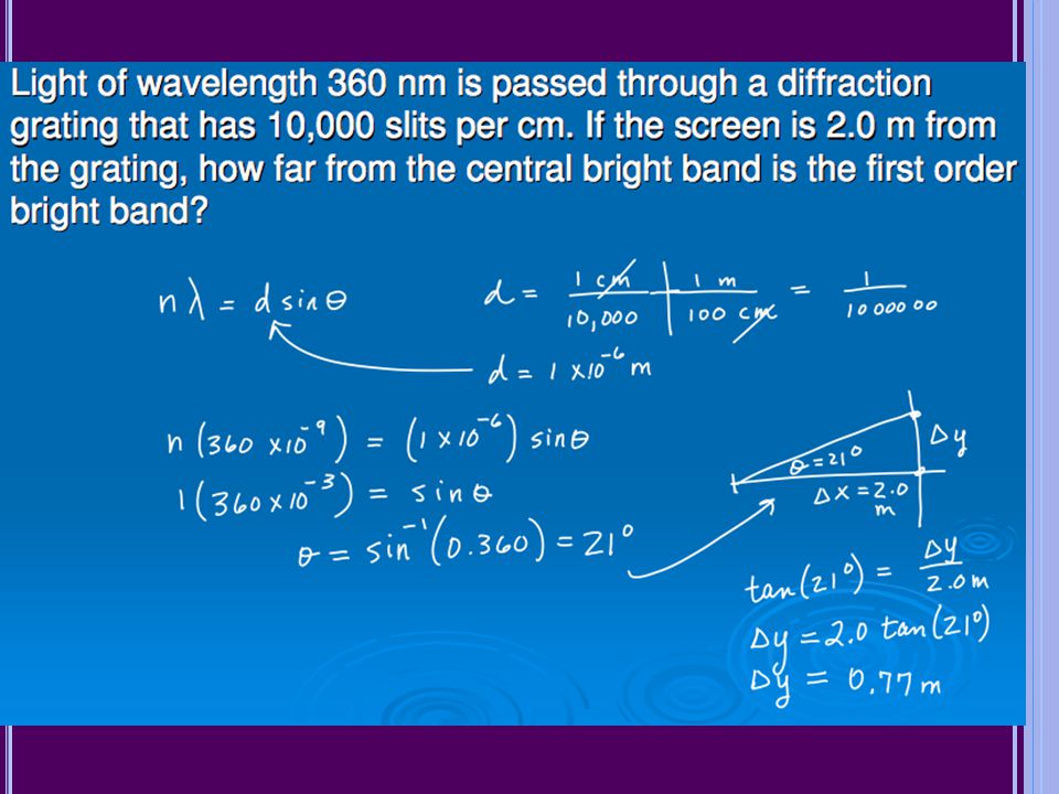
Light of wavelength 360 nm is passed through a diffraction grating that has 10,000 slits per cm. If the screen is 2.0 m from the grating, how far from the central bright band is the first order bright band?

7
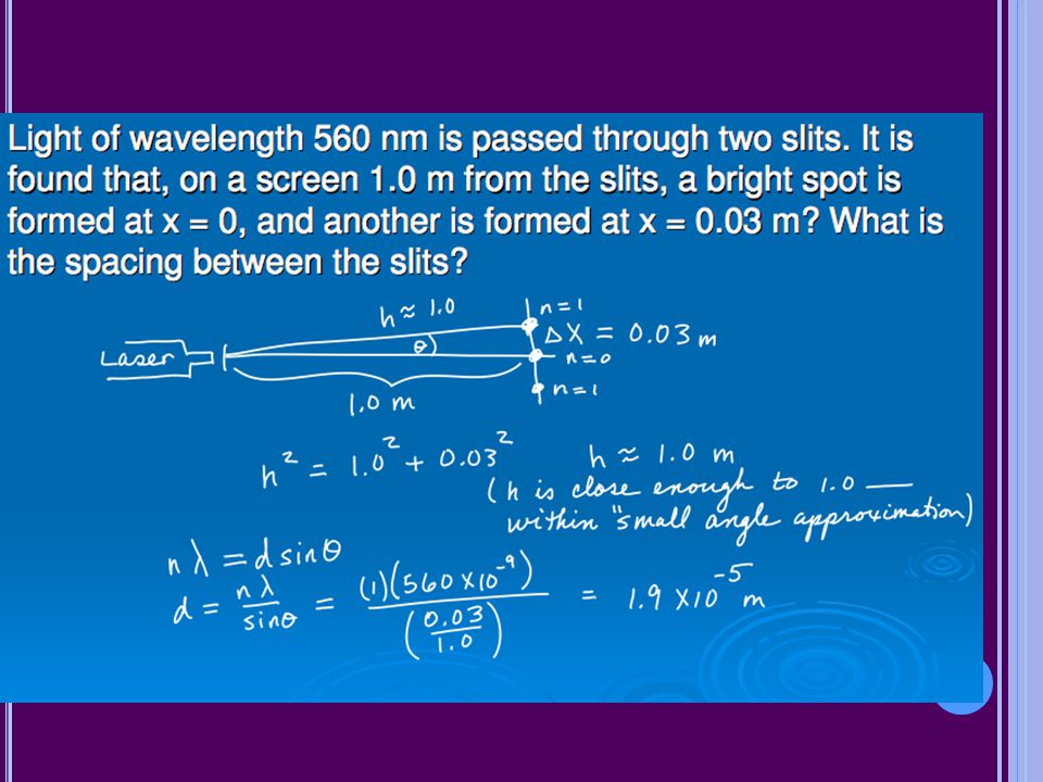
Light of wavelength 560 nm is passed through two slits
Light of wavelength 560 nm is passed through two slits. It is found that, on a screen 1.0 m from the slits, a bright spot is formed at x = 0, and another is formed at x = m. What is the spacing between the slits?

9
REFLECTION Reflected sound can be heard as an echo
Light waves can be drawn as “rays” to diagram light reflected off mirrors

10
REFLECTION AND PLANE MIRRORS
Law of Reflection

11
Mirrors can be MIRRORS Plane (flat) Spherical
Convex – reflective side curves outward Concave – reflective side curves inward

12
OPTICAL IMAGES Nature Orientation Size Real (converging rays)
Virtual (diverging rays) Orientation Upright Inverted Size True Enlarged Reduced
 Orientation. Upright. Inverted. Size. True. Enlarged. Reduced.")
13
MIRRORS AND RAY TRACING
Ray tracing is a method of constructing an image using the model of light as a ray We use ray tracing to construct optical images produced by mirrors and lenses Ray tracing lets us describe what happens to the light as it interacts with a medium

14
RAY TRACING: PLANE MIRRORS
Use at least two rays to construct the image

15
PROBLEM 4 Standing 2.0 m in front of a small vertical mirror, you see the reflection of your belt buckle, which is 0.70 m below your eyes. What is the vertical location of the mirror relative to the level of your eyes? If you move backward until you are 6.0 m from the mirror, will you still see the buckle, or will you see a point on your body that is above or below the buckle? Explain.

16
SOLUTION

17
SPHERICAL MIRRORS Concave Convex

18
PARTS OF A SPHERICAL CONCAVE MIRROR
+ - Vertex Center Focus Principle axis

19
PARTS OF A SPHERICAL CONCAVE MIRROR
The focal length is half the radius of curvature R = 2f The focal length is positive for a concave mirror because it is on the shiny side Rays parallel to the optical axis all pas through the focus

20
RAY TRACING FOR CONCAVE MIRRORS
You must draw at least TWO of the three principal rays to construct an image: The p-ray: parallel to the principal axis, then reflects through the focus The f-ray: travels through the focus then reflects back parallel to the principal axis The c-ray: travels through the center, then reflects back through the center

21
CONCAVE MIRRORS Diagram the following images:
Object outside the center of curvature Object at the center of curvature Object between center of curvature and focus Object at the focal point Object inside the focus

23
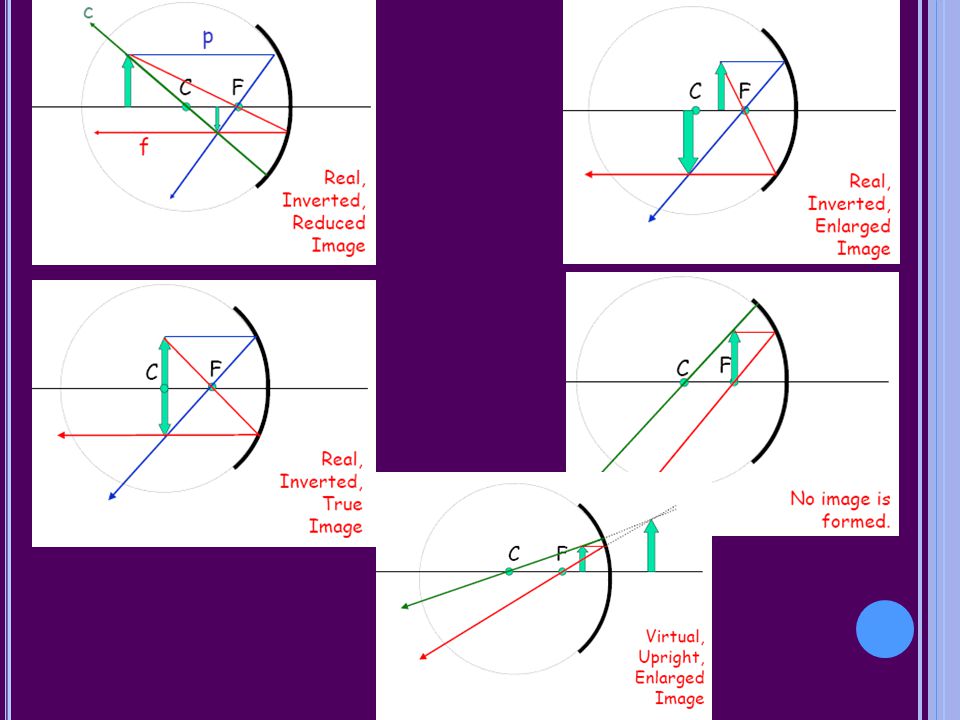
SPHERICAL CONCAVE MIRROR (OBJECT OUTSIDE CENTER)
F Real, Inverted, Reduced Image f

24
SPHERICAL CONCAVE MIRROR (OBJECT AT CENTER)
F Real, Inverted, True Image

25
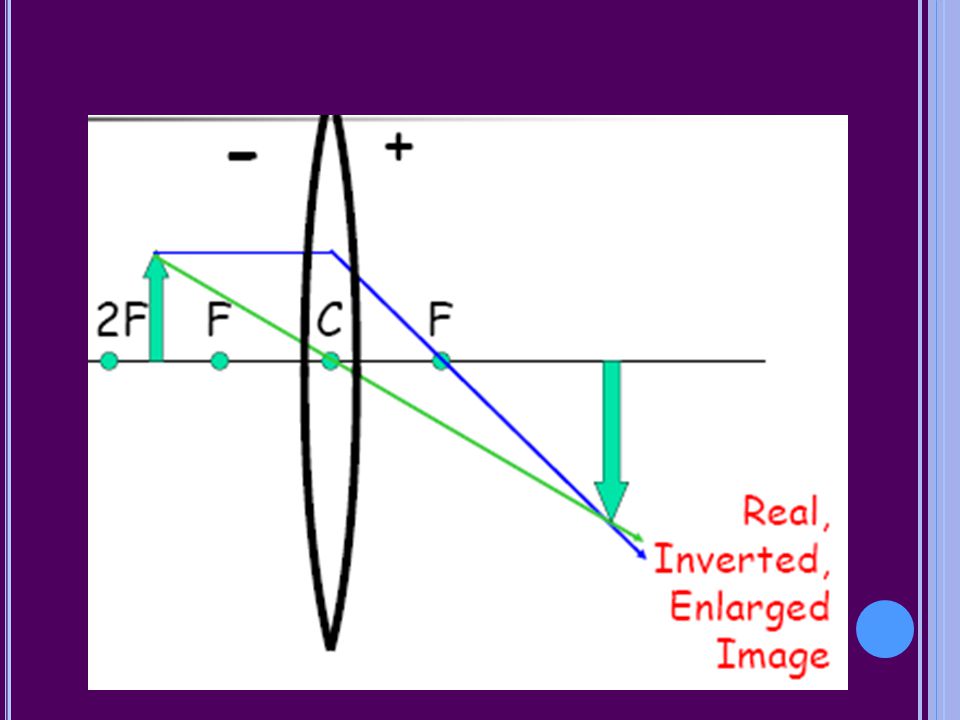
SPHERICAL CONCAVE MIRROR (OBJECT BETWEEN CENTER AND FOCUS)
Real, Inverted, EnlargedImage

26
SPHERICAL CONCAVE MIRROR (OBJECT AT FOCUS)
No image

27
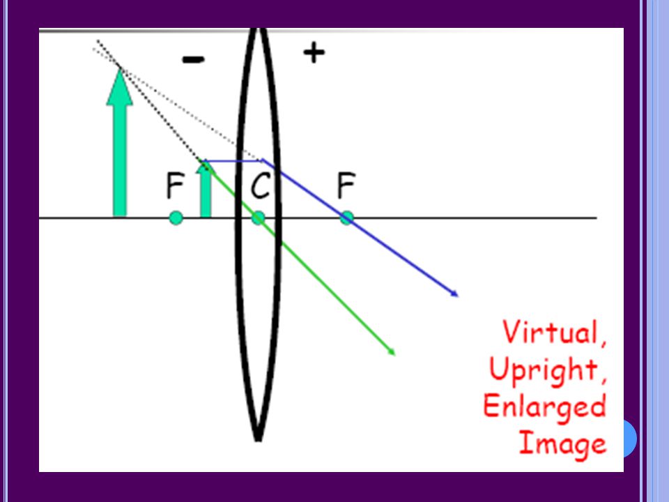
SPHERICAL CONCAVE MIRROR (OBJECT INSIDE FOCUS)
Virtual, Upright, Enlarged Image

28
MIRROR EQUATION 1 & MIRROR EQUATION 2
1/si + 1/s0 = 1/f si: image distance s0: object distance f: focal length M = hi/h0 = -si/s0 si: image distance s0: object distance hi: image height h0: object height M: magnification

29
SIGN CONVENTIONS Focal length (f) Magnification (M) Image Distance
Positive for concave mirrors Negative for convex mirrors Magnification (M) Positive for upright images Negative for inverted images Enlarged: M > 1 Reduced: M < 1 Image Distance si is positive for real images si is negative for virtual images Practice: A spherical concave mirror, focal length 20 cm, has a 5-cm high object placed 30 cm from it Draw a ray diagram and construct the image Use mirror equations to calculate the position, magnification, and size of the image Name the image
 Positive for upright images. Negative for inverted images. Enlarged: M > 1. Reduced: M < 1. Image Distance. si is positive for real images. si is negative for virtual images. Practice: A spherical concave mirror, focal length 20 cm, has a 5-cm high object placed 30 cm from it. Draw a ray diagram and construct the image. Use mirror equations to calculate the position, magnification, and size of the image. Name the image.")
30
Calculate the position, magnification, and size of the image.
Solution: A spherical concave mirror, focal length 20 cm, has a 5-cm high object placed 30 cm from it. Calculate the position, magnification, and size of the image. Name the image real, inverted, enlarged.

31
PARTS OF A SPHERICAL CONVEX MIRROR
The focal length is half the radius of curvature and both are on the dark side of the mirror The focal length is negative

32
RAY TRACING Construct the image for an object located outside a spherical convex mirror Name the image

33
PRACTICE 5 A spherical concave mirror, focal length 15 cm, has a 4- cm high object placed 10 cm from it Draw a ray diagram and construct the image Use the mirror equations to calculate position, magnification, and size of image Name the image

34
a) Use the mirror equations to calculate
Problem: A spherical convex mirror, focal length 15 cm, has a 4-cm high object placed 10 cm from it. a) Use the mirror equations to calculate the position of image the magnification the size of image b) Name the image virtual, upright, reduced size
 Use the mirror equations to calculate. the position of image. the magnification. the size of image. b) Name the image virtual, upright, reduced size.")
35
SPHERICAL MIRRORS Image is real when object is outside focus
Concave Convex Image is real when object is outside focus Image is virtual when object is inside focus Focal length is positive Image is ALWAYS virtual Focal length is negative

36
Real vs Virtual images Real Virtual Formed by converging light rays
si is positive when calculated with mirror equation Virtual Formed by diverging light rays si is negative when calculated with mirror equation

37
Upright vs Inverted images
Always virtual if formed by one mirror or lens hi is positive when calculated with mirror/lens equation Inverted Always real if formed by one mirror or lens hi is negative when calculated with mirror/lens equation

38
WAVE BEHAVIOR 2: REFRACTION
Refraction occurs when a wave is transmitted from one medium to another Refracted waves may change speed and wavelength Refraction is almost always accompanied by some reflection Refracted waves do NOT change frequency

39
REFRACTION OF LIGHT Refraction causes a change in speed of light as it moves from one medium to another Refraction can cause bending of the light ray at the interface between media Index of Refraction (n): n = speed of light in vacuum / speed of light in medium n = c/v
: n = speed of light in vacuum / speed of light in medium. n = c/v.")
40
SNELL’S LAW n1sinΘ1 = n2sinΘ2

41
SNELL’S LAW When the index of refraction increases, light bends TOWARD the normal When the index of refraction decreases, light bends AWAY FROM the normal

42
PROBLEM 6! Light enters an oil from the air at an angle of 50° with the normal, and the refracted beam makes an angle of 33° with the normal Draw the situation Calculate the index of refraction of the oil Calculate the speed of light in the oil

43
Solution: Light enters an oil from the air at an angle of 50o with the normal, and the refracted beam makes an angle of 33o with the normal. Draw this situation. Calculate the index of refraction of the oil. Calculate the speed of light in the oil

44
PRISM PROBLEMS (7) Light enters a prism as shown, and passes through the prism a. Complete the path of light through the prism and show the angle it will make when it leaves the prism b. If the refractive index of the glass is 1.55, calculate the angle of refraction when it leaves the prism c. How would the answer to (b) change if the prism were immersed in water?
 change if the prism were immersed in water")
45
Solution: Light enters a prism as shown, and passes through the prism.
Complete the path of the light through the prism, and show the angle it will make when it leaves the prism. If the refractive index of the glass is 1.55, calculate the angle of refraction when it leaves the prism. How would the answer to b) change if the prism were immersed in water? 30o 60o glass air q2 c) In water, the angle of the light as it leaves the glass would be smaller, since the indices of refraction would be more similar and there would be less bending.
 change if the prism were immersed in water 30o. 60o. glass. air. q2. c) In water, the angle of the light as it leaves the glass would be smaller, since the indices of refraction would be more similar and there would be less bending.")
46
PRISM PROBLEMS (8) Light enters a prism made of air from glass
Complete the path of the light through the prism, and show the angle it will make when it leaves the prism If the refractive index of the glass is 1.55, calculate the angle of refraction when it leaves the prism

47
Problem: Light enters a prism made of air from glass.
Complete the path of the light through the prism, and show the angle it will make when it leaves the prism. If the refractive index of the glass is 1.55, calculate the angle of refraction when it leaves the prism. 60o glass air 30o 30o q2

48
CRITICAL ANGLE OF INCIDENCE
The smallest angle of incidence for which light cannot leave a medium is called the critical angle of incidence If light passes into a medium with a greater refractive index than the original medium, it bends away from the normal and the angle of refraction is greater than the angle of incidence If the angle of refraction is ≥90°, the light cannot leave the medium and no refraction occurs We call this TOTAL INTERNAL REFLECTION

49
TOTAL INTERNAL REFLECTION
Calculating the Critical Angle:

50
PRACTICE NO. 9 What is the critical angle of incidence for a gemstone with refractive index 2.45 if it is in air? If you immerse it in water (refractive index 1.33), what does this do to the critical angle of incidence?
, what does this do to the critical angle of incidence")
51
Solution: What is the critical angle of incidence for a gemstone with refractive index 2.45 if it is in air? If you immerse the gemstone in water (refractive index 1.33), what does this do to the critical angle of incidence? It increases the critical angle of incidence because there is less difference in the refractive indices.
, what does this do to the critical angle of incidence It increases the critical angle of incidence because there is less difference in the refractive indices.")
52
LENSES REFRACT LIGHT: Converging (Convex) Diverging (Concave)
 Diverging (Concave)")
53
LENS RAY TRACING Ray tracing is used for lenses also. Use the same principal rays used with mirrors. You must draw TWO of the three: the p-ray: parallel to the principal axis, refracts through the focus the f-ray: travels through the focus, then refracts parallel to the principal axis the c-ray: travels through the center and continues without bending Use the same equations we used for mirrors

54
CONVERGING LENSES

55
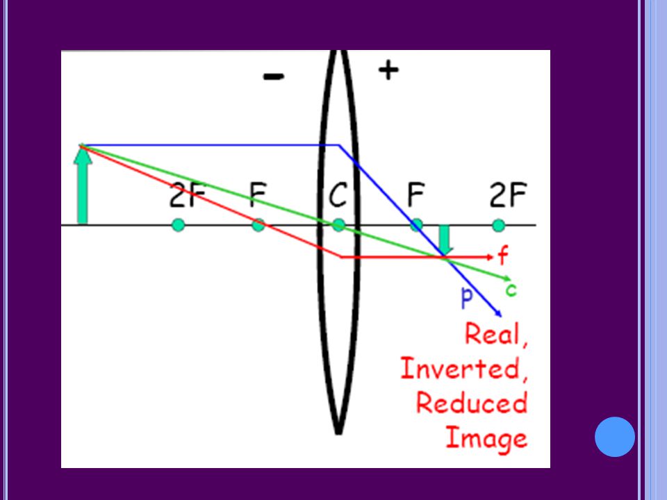
CONSTRUCT THE FOLLOWING IMAGES:
Object located outside 2F for a converging lens Object located at 2F Object located between F and 2F Object at the focus Object inside the focus

61
FOR CONVERGING LENSES f is positive so is positive
si is positive for real images and negative for virtual images M is negative for real images and positive for virtual images hi is negative for real images and positive for virtual images

62
DIVERGING LENSES Construct an image for an object located in front of a diverging lens:

63
FOR DIVERGING LENSES f is negative so is positive si is negative
M is positive and < 1 hi is positive and < ho

Similar presentations