Download presentation
Presentation is loading. Please wait.

1
Chapter 3 – Hydraulic Pumps
Topics Pump Flow and Pressure Pump Drive Torque and Power Pump Efficiency Pump Types Pressure Compensated Pumps Cavitation and Aeration Symbols Pump Specifications

2
Hydraulic Power Unit Relief Valve

3
Basic Pump The basic operating principle that moves fluid through a pump is similar in all pumps Enlarging the volume of a chamber allows fluid to enter the pump Reducing the chamber volume moves fluid to the system Inlet and discharge valves or ports control fluid movement through the pump

4
How Pumps Work In a rotary pump, the pumping action is produced by revolving components In a reciprocating pump, the rotating motion of the pump input shaft is changed to reciprocating motion, which then produces the pumping action

5
Basic Pump Increasing the size of the pumping chamber moves fluid into the pump

6
Basic Pump Reducing the size of the pumping chamber forces fluid into the system

7
Basic Pump The maximum pressure developed in a hydraulic system is determined by: Resistance to fluid flow in the system Force the prime mover can exert The output flow rate of a hydraulic pump is determined by: Volume of the pumping chamber Operating speed of the prime mover

8
Path of least resistance:
Pressure Path of least resistance: If there is no force (load) on a cylinder there is no pump pressure! Pump What will happen to cylinders A & B when power is applied to the pump? Cylinder A Dia. = 4” with a load of 2000 lbs Cylinder B Dia. = 8” with a load of 4000 lbs Cylinder A Cylinder B
 on a cylinder there is no pump pressure! Pump. What will happen to cylinders A & B when power is applied to the pump Cylinder A. Dia. = 4 with a load of 2000 lbs. Cylinder B. Dia. = 8 with a load of 4000 lbs. Cylinder A. Cylinder B.")
9
Cylinder A Dia. = 4” with a load of 2000 lbs Area = 12.566 in2
P= F/A = psi Pump Cylinder A Cylinder B Cylinder B Dia. = 8” with a load of 4000 lbs Area = in2 P= F/A = psi Cylinder B moves first until it is fully extended and then Cylinder A extends

10
Displacement – The volume of fluid that is discharged per cycle.
Cycle – One revolution of the pump shaft. Theoretical Flow Rate - 𝑄 𝑇 𝑄 𝑇 = 𝑉 𝑃 ∙𝑁 𝑄 𝑇 = 𝑉 𝑃 ∙𝑁 1000 𝑉 𝑝 =𝑝𝑢𝑚𝑝 𝑑𝑖𝑠𝑝𝑙𝑎𝑐𝑒𝑚𝑒𝑛𝑡 𝑖𝑛 3 𝑟𝑒𝑣 , 𝑐𝑚 3 𝑟𝑒𝑣 𝑁=𝑑𝑟𝑖𝑣𝑒 𝑠𝑝𝑒𝑒𝑑 𝑅𝑒𝑣 𝑀𝑖𝑛

11
EX – A pump has a displacement of 3 𝑖𝑛 3 𝑟𝑒𝑣 and is driven at 1800rpm
EX – A pump has a displacement of 3 𝑖𝑛 3 𝑟𝑒𝑣 and is driven at 1800rpm. What is the theoretical flow rate? 𝑄 𝑇 = 𝑉 𝑃 ∙𝑁 231 = 3 𝑖𝑛 3 𝑟𝑒𝑣 ∙ 1800 𝑟𝑒𝑣 𝑚𝑖𝑛 𝑖𝑛 3 𝑔𝑎𝑙 𝑄 𝑇 =23.4 𝑔𝑎𝑙 𝑚𝑖𝑛

12
Pump Drive and Torque Power
Prime mover supplies input power to the pump by driving the pump shaft at a rotational speed. Pressure on the pump resists rotation. Prime mover must generate enough torque to turn the shaft against the resistance.

13
Theoretical Torque – 𝑇 𝑇 = 𝑝∙ 𝑉 𝑝 2𝜋 𝑝=𝑝𝑟𝑒𝑠𝑠𝑢𝑟𝑒 (𝑝𝑠𝑖,𝑃𝑎) 𝑉 𝑃 =𝑑𝑖𝑠𝑝𝑙𝑎𝑐𝑒𝑚𝑒𝑛𝑡 𝑖𝑛 3 𝑟𝑒𝑣 , 𝑐𝑚 3 𝑟𝑒𝑣 𝑐𝑚 3 𝑟𝑒𝑣 𝑡𝑜 𝑚 3 𝑟𝑒𝑣 is 1 𝑚 3 =1,000,000 𝑐𝑚 3

14
Ex: A hydraulic pump with a displacement of 4 𝑖𝑛 3 𝑟𝑒𝑣 is selected for a system that will operate at a maximum pressure of 5000 psi. What is the required drive torque? 𝑇 𝑇 = 𝑝∙ 𝑉 𝑝 2𝜋 = 5000 𝑙𝑏 𝑖𝑛 2 ∙ 4 𝑖𝑛 3 𝑟𝑒𝑣 2𝜋 =3183 𝑖𝑛∙𝑙𝑏𝑠

15
Ex: A hydraulic pump with a displacement of 30 𝑐𝑚 3 𝑟𝑒𝑣 is selected for a system that will operate at a maximum pressure of 40,000kPa. What is the required drive torque? Convert to 𝑚 3 𝑟𝑒𝑣 30 𝑐𝑚 3 𝑟𝑒𝑣 ∙ 1 𝑚 3 1,000,000 𝑐𝑚 3 = 𝑚 3 𝑟𝑒𝑣 𝑇 𝑇 = 𝑝∙ 𝑉 𝑝 2𝜋 = 𝑁 𝑚 2 ∙ 𝑚 3 𝑟𝑒𝑣 2𝜋 =191 𝑁∙𝑚

16
Power 𝐻𝑃 1 = 𝑇∙𝑁 63025 𝑘𝑊 1 = 𝑇∙𝑁 9550

17
EX: An electric motor drives a pump at 1500 rpm with a torque of 300 𝑖𝑛∙𝑙𝑏. What is the power input to this pump? 𝐻𝑃 1 = 𝑇∙𝑁 63025 𝐻𝑃 1 = 300 𝑖𝑛∙𝑙𝑏∙1500 𝑟𝑝𝑚 =7 ℎ𝑝

18
Pump Efficiency Ratio of actual flow rate to theoretical flow rate Volumetric efficiency: 𝜂 𝑣 = 𝑄 𝐴 𝑄 𝑇 𝜂=𝑒𝑡𝑎

19
Pump Efficiency 𝑄 𝐴 = 𝜂 𝑣 ∙ 𝑉 𝑝 ∙𝑁 𝑉 𝑝 = 𝑖𝑛 3 𝑟𝑒𝑣 𝑁=𝑟𝑝𝑚 𝑄 𝐴 = 𝜂 𝑣 ∙ 𝑉 𝑝 ∙𝑁 𝑉 𝑝 = 𝑐𝑚 3 𝑟𝑒𝑣 𝑁=𝑟𝑝𝑚

20
EX: A pump has a displacement of 3 𝑖𝑛 3 𝑟𝑒𝑣 and a volumetric efficiency of If it is driven at 1300 rpm, what will its actual flow rate be? 𝑄 𝐴 = 𝜂 𝑣 ∙ 𝑉 𝑝 ∙𝑁 231 𝑄 𝐴 =0.93∙ 3 𝑖𝑛 3 𝑟𝑒𝑣 ∙1300 𝑟𝑒𝑣 𝑚𝑖𝑛 𝑖𝑛 3 𝑔𝑎𝑙 𝑄 𝐴 =15.70 𝑔𝑝𝑚

21
Overall efficiency 𝜂 𝑂 = 𝐻𝑃 𝐻 𝐻𝑃 𝐼 𝜂 𝑂 = 𝑘𝑊 𝐻 𝑘𝑊 𝐼 Just like regular efficiency – output/input

22
EX: A pump has and overall efficiency of 0
EX: A pump has and overall efficiency of 0.88 and a flow rate of 40 lpm is to be used in a system that has a maximum operating pressure of 20,000kPa. What is the input power require? Calculate the hydraulic power: 𝑘𝑊 𝐻 = 𝑝∙𝑄 60,000 = 𝑘𝑃𝐴∙40𝑙𝑝𝑚 =13.33𝑘𝑊 Calculate the input power: 𝑘𝑊 1 = 𝑘𝑊 𝐻 𝜂 0 = 13.33𝑘𝑊 0.88 =1514𝑘𝑊

25
Hydraulic pumps can be classified using three basic Characteristics:
Pump Classifications Hydraulic pumps can be classified using three basic Characteristics: Displacement Pumping motion Fluid delivery characteristics

26
Displacement Pump Displacement relates to how the output of the pump reacts to system loads Positive-displacement pumps produce a constant output per cycle A non-positive-displacement pump has large internal clearances Allows fluid slippage in the pump Results in varying flow output as system load varies

27
Displacement Pump Positive-displacement pump

28
Displacement Pump Non-positive-displacement pump

29
Pumping Motion Classifications
The basic pumping motions used in hydraulic pumps are: Rotary Gear pumps are rotary pumps Reciprocating Piston pumps are reciprocating pumps Reciprocating piston movement

30
Fluid Delivery Classifications
Hydraulic pumps are classified as either fixed or variable delivery Fixed-delivery pumps have pumping chambers with a volume that cannot be changed; the output is the same during each cycle In variable-delivery designs, chamber geometry may be changed to allow varying flow from the pump

31
Fluid Delivery Classifications
Gear pumps are fixed-delivery pumps

32
Fluid Delivery Classifications
Piston pumps may or may not be variable-delivery pumps

33
Variable Displacement Pumps

34
Variable Displacement Pumps

35
Pump Selection When selecting a pump for a circuit, factors that must be considered are: System operating pressure Flow rate Cycle rate Expected length of service Environmental conditions Cost

36
Pump Design, Operation, and Application
Gear pumps: positive-displacement, fixed-delivery, rotary units external or internal gear teeth configurations

37
Pump Design, Operation, and Application
Pumping action of gear pumps results from unmeshing and meshing of the gears As the gears unmesh in the inlet area, low pressure causes fluid to enter the pump As the pump rotates, fluid is carried to the pump discharge area When the gears mesh in the discharge area, fluid is forced out of the pump into the system Flow outputs from below 1 gpm to 150 gpm Pressure rating range up to 3000 psi

38
Pump Design, Operation, and Application
The gerotor pump design is an internal-gear pump Uses two rotating, gear-shaped elements that form sealed chambers The chambers vary in volume as the elements rotate Fluid comes into the chambers as they are enlarging and is forced out as they decrease in size

39
Pump Design, Operation, and Application
The gerotor is a common internal-gear design

40
Pump Design, Operation, and Application
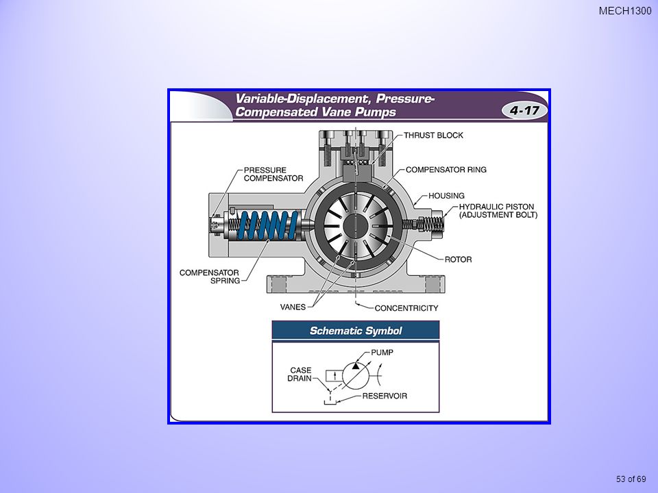
Vane pumps are positive-displacement, fixed or variable delivery, rotary units. Design is commonly used in industrial applications Delivery can range up to 75 gpm Maximum pressure of about 2000 psi

41
Pump Design, Operation, and Application
Vane pump consists of a slotted rotor, fitted with moveable vanes, that rotates within a cam ring in the pump housing Rotor is off center in the ring, which creates pumping chambers that vary in volume as the pump rotates As chamber volume increases, pressure decreases, bringing fluid into the pump As volume decreases, fluid is forced out into the system

42
Pump Design, Operation, and Application

43
Pump Design, Operation, and Application
Piston pumps: positive-displacement, fixed- or variable-delivery, reciprocating units provide high volumetric efficiency (90%), high operating pressure (10,000 psi or higher), high-speed operation
, high operating pressure (10,000 psi or higher), high-speed operation.")
45
Pump Design, Operation, and Application
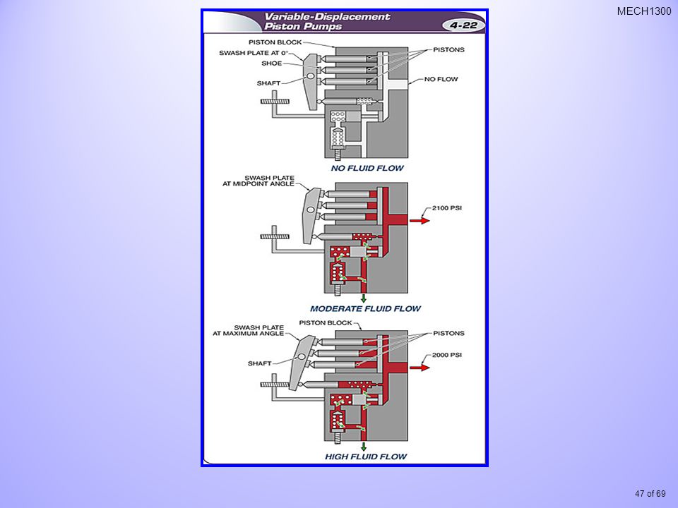
A basic piston pump consists of a housing that supports a pumping mechanism and a motion-converting mechanism Pumping mechanism is a block containing cylinders fitted with pistons and valves Motion converter changes rotary to reciprocating motion via cams, eccentric ring, swash plate, or bent-axis designs Rotating the pump shaft causes piston movement that pumps the fluid

46
Pump Design, Operation, and Application
Piston pump classification is based on the relationship between the axes of the power input shaft and piston motion Axial Inline Bent axis

48
Pump Design, Operation, and Application
Piston pump classification is based on the relationship between the axes of the power input shaft and piston motion Radial have the highest continuous operating pressure capability of any of the pumps regularly used in hydraulic systems are available with operating pressure ratings in the 10,000 psi range

49
Pump Design, Operation, and Application
A stationary-cylinder radial-piston pump

50
Pump Design, Operation, and Application
Radial Reciprocating

51
Pump Design, Operation, and Application
Screw pumps have pumping elements that consist of one, two, or three rotating screws the screws rotate, fluid is trapped and carried along to the discharge of the pump screw pumps operate at a very low noise level

52
Additional Design Features of Pumps
Pressure compensation reduces energy consumption

54
Additional Design Features of Pumps
A dual-pump design Sauer-Danfoss, Ames, IA

56
Gallons per minute is the number of gallons a pump can force into the system every minute and thus the amount of fluid flow that pump can produce. in3

57
Design & Operating Considerations
Cavitation is caused when inlet line pressure drops below the vapor pressure of the fluid and bubbles form Reduces lubricity of the system fluid Collapsing bubbles produce severe shock waves that can damage pump parts Collapsing bubbles also produce noisy pump operation

58
Design & Operating Considerations

59
Design & Operating Considerations
Entrained air is air suspended in fluid Enters the inlet line through leaks on the suction side of the pump Can produce a result similar to cavitation

60
Design & Operating Considerations
Testing inlet line pressure can help indicate which condition exists High negative pressure (vacuum) indicates cavitation Pressure closer to 0 psi may indicate entrained air
 indicates cavitation. Pressure closer to 0 psi may indicate entrained air.")
61
Design & Operating Considerations
The inlet line of the pump must be carefully sized and configured to eliminate cavitation and air entrainment Fluid velocity in the line should not exceed feet per second Lines should be no smaller than the diameter of the pump inlet fitting Strainer and inlet line filters must not restrict fluid flow

62
Design & Operating Considerations
Pump Flow Rate Q (gpm) = (V * N)/231 Q (lpm) = (V * N)/1000 Q – flow rate (in3/min, cm3/min) V – pump displacement (in3/rev, cm3/rev) N – drive speed (rpm) Horsepower required for a given flow rate and pressure HP = (P*Q)/1714 P in psi; Q in gpm; HP in hp kW = (P*Q)/60,000 P in kPa; Q in lpm; kW in kW
 = (V * N)/231. Q (lpm) = (V * N)/1000. Q – flow rate (in3/min, cm3/min) V – pump displacement (in3/rev, cm3/rev) N – drive speed (rpm) Horsepower required for a given flow rate and pressure. HP = (P*Q)/1714. P in psi; Q in gpm; HP in hp. kW = (P*Q)/60,000. P in kPa; Q in lpm; kW in kW.")
63
Glossary Application information Axial piston pump
Information supplied by a manufacturer describing conditions and limits of operation in which a product may be expected to successfully operate. Axial piston pump A hydraulic pump using a design in which the reciprocating motion of the pistons is parallel to the power input shaft.

64
Glossary Balanced-vane pump
A hydraulic vane pump using a design with two inlet and outlet chambers that balance the load forces on the bearings of the pump rotor shaft.

65
Glossary Cavitation The formation of gas within a liquid stream that occurs when pressure drops below the vapor pressure of the liquid; may result in excessive noise and pump damage. The condition in a hydraulic pump can result from restricted inlet flow or excessive oil viscosity.

66
Glossary Dual pump Fixed-delivery pump
A design in which two pumps are built into a single case. The pumps may be rated at different pressures and flow outputs to provide additional flexibility. Fixed-delivery pump Any hydraulic pump design that has a nonadjustable fluid delivery rate.

67
Glossary Gear pump A hydraulic pump design that uses gears to move fluid through the pumping chamber of the component. Gears may have internal or external teeth.

68
Glossary General hydraulic horsepower
A computed figure used in hydraulic systems based on fluid flow and pressure. Equal to fluid flow weight in pounds per minute multiplied by the pressure in feet of head divided by 33,000 foot pounds per minute.

69
Glossary Gerotor design
A common internal-gear pump or motor design. The pumping chamber of these units has two gear-shaped elements that form varying-size chambers as they rotate.

70
Glossary Impeller The rotating component of a dynamic compressor or impeller pump. Energy is increased in the fluid as centrifugal force causes flow through the unit.

71
Glossary Mechanical efficiency Non-positive-displacement pump
The theoretical horsepower needed to operate a pump or compressor divided by the actual horsepower required. Non-positive-displacement pump A pump that does not have a variable-volume pumping chamber. An impeller or other device is used to move the fluid. The inertia of that fluid movement produces pressure when flow is resisted.

72
Glossary Power unit The unit in a hydraulic system that provides energy for the system, moves fluid through the system, provides a safe maximum limit of system pressure, and maintains desired system temperature and fluid cleanliness.

73
Glossary Radial-piston pump
A positive-displacement piston pump design in which the pistons are located in a cylinder block or housing that is perpendicular to the power input shaft.

74
Glossary Reciprocating pump
One of a variety of pump designs using reciprocating pistons to move fluid. The drive mechanisms vary, but a reciprocating piston moves the fluid against resistance from the system actuator.

75
Glossary Screw pump A pump unit that uses intermeshing screws to form chambers that linearly move hydraulic oil through the pump. The design provides a continuous, positive displacement of the oil.

76
Glossary Stationary-cylinder design Swash plate
A radial-piston hydraulic pump design in which a cam operates pistons located in a fixed cylinder block. Swash plate An inclined disk in a hydraulic axial-piston pump or motor that causes the pistons to reciprocate.

Similar presentations


 Hydraulic Power (pumps).>")


