Download presentation
Presentation is loading. Please wait.

2
1. Bed 2. Headstock 3. Tailstock 4. Carriage 5. Feed Mechanism

3
Lathe Bed

4
It is supported on broad box-section columns and is made of cast iron. Its upper surface is ground and the guiding and sliding surfaces are provided. The bed consists of two heavy metal slides running lengthwise, with ways or V' s formed upon them. The outer guide ways provide bearing and sliding surfaces for the carriage, and the inner ways for the tail stock. Three major units mounted on bed are the head-stock, the tail stock, and the carriage. The ground guiding and sliding surfaces on the lathe bed ensure the accuracy of alignment of these three units. The headstock is permanently fixed to the bed, the tailstock is adjustable for position to accommodate work pieces of different lengths.

5
The carriage can be traversed to and between the headstock and the tailstock either manually or by power. Lathe bed is made of high grade special cast iron having high vibration damping qualities. Lathe bed is secured rigidly over cabinet leg and end leg and all other parts are fitted on it. Top surface of bed is machined accurately. The important considerations in design of lathe bed are its rigidity, alignment and accuracy. In its use, every care should be taken to avoid formation of scratches, nicks and dents by falling tools/spanners and it should be lubricated regularly to avoid rusting.

6
The lathe bed being the main guiding member for accurate machining work, it should be sufficiently rigid to prevent deflection under cutting forces; should be massive with sufficient depth and width to absorb vibrations; should be designed to resist the twisting stresses set up due to resultant of two forces; should be seasoned naturally to relieve the stresses set up during casting

7
It supports the main spindle in the bearings and aligns it properly. It also houses necessary transmission mechanism with speed changing levers to obtain different speeds. Cone pulley or gears or combination of both could be used to change speed of spindle. Accessories mounted on head stock spindle: A. Three jaw chuck B. Four jaw chuck C. Lathe center and lathe dog D. Collet chuck E. Face plate F. Magnetic chuck

9
The complete head stock consists of the headstock casting which is located on the ways of the bed at the left side of the operator, the hollow spindle in which the Live centre is rigidly held by a taper, and the necessary gears and mechanisms for obtaining the various spindle speeds. The centerline of the headstock is parallel to the guide ways, in both horizontal and vertical planes. All the modern lathes employ all-geared headstock. However, where greater simplicity and low cost are the criteria, cone-drive headstock can be used. A geared headstock may be driven either direct from a line shaft or from an independent motor, the drive being transmitted to the constant speed main drive pulley.

10
Headstock also incorporates the self-contained clutch and brake mechanism by which the pulley may be coupled to the shafting in the headstock, as required. Usually arrangements are provided so that when the pulley is running free the spindle is braked automatically. Sliding gearing is generally employed for obtaining the various speed changes, the gears being mounted on multi spindle shafts and traversed axially thereon by external control levers through selector mechanism. A separate speed change gearbox is placed below headstock to reduce the speed in order to have different feed rates for threading and automatic lateral movements of carriage. The feed shaft is used for most turning operations and lead screw is used for cutting threads etc

11
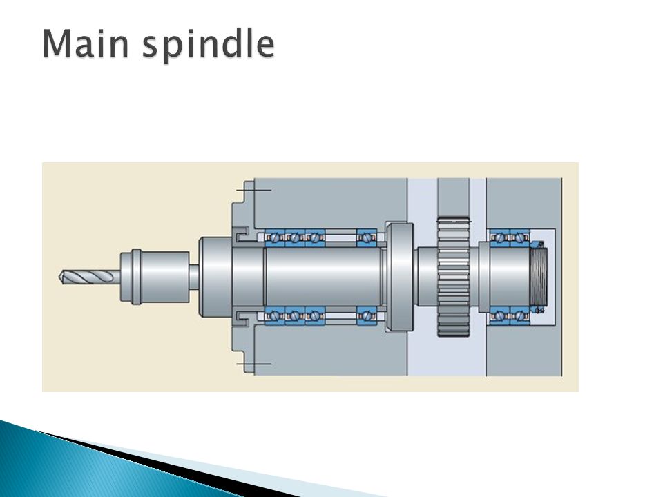
It-is a hollow cylindrical shaft and long slender jobs can pass through it. The spindle end facing the tailstock is called the spindle nose. The spindle nose has a morse taper hole (self-locking taper) and threads on outside. The morse taper is used to accommodate lathe centre or collet chuck and threaded portion for chuck or face plate. The design of the lathe spindle and its bearings forms important feature, as the thrust of the cutting tool tends to deflect the spindle. Anti-friction bearings are used in the headstock, and the spindle, which is made of high-tensile steel suitably hardened and tempered, is supported in roller bearings. The front spindle bearings take both the axial and radial loads on the spindle and the rear bearing is so designed that the spindle may float axially from the front bearings to allow the expansion and contraction.
 and threads on outside. The morse taper is used to accommodate lathe centre or collet chuck and threaded portion for chuck or face plate. The design of the lathe spindle and its bearings forms important feature, as the thrust of the cutting tool tends to deflect the spindle. Anti-friction bearings are used in the headstock, and the spindle, which is made of high-tensile steel suitably hardened and tempered, is supported in roller bearings. The front spindle bearings take both the axial and radial loads on the spindle and the rear bearing is so designed that the spindle may float axially from the front bearings to allow the expansion and contraction..")
12
The spindle nose is designed for rapid mounting and removal of chucks and fixtures on it, and also for positioning them accurately and securely. Screwed type spindle nose with two locating cylindrical surfaces in front and rear, and threads in between is used. The overhang of the spindle nose is kept to minimum to guard against bending. The spindle is made hollow to allow long bars to pass through. On the front side, it has a taper socket to mount a live centre which rotates with the spindle. The various face plates and chucks are secured to the flange of the spindle nose by bolts or studs, and positioned by taper spigot.

14
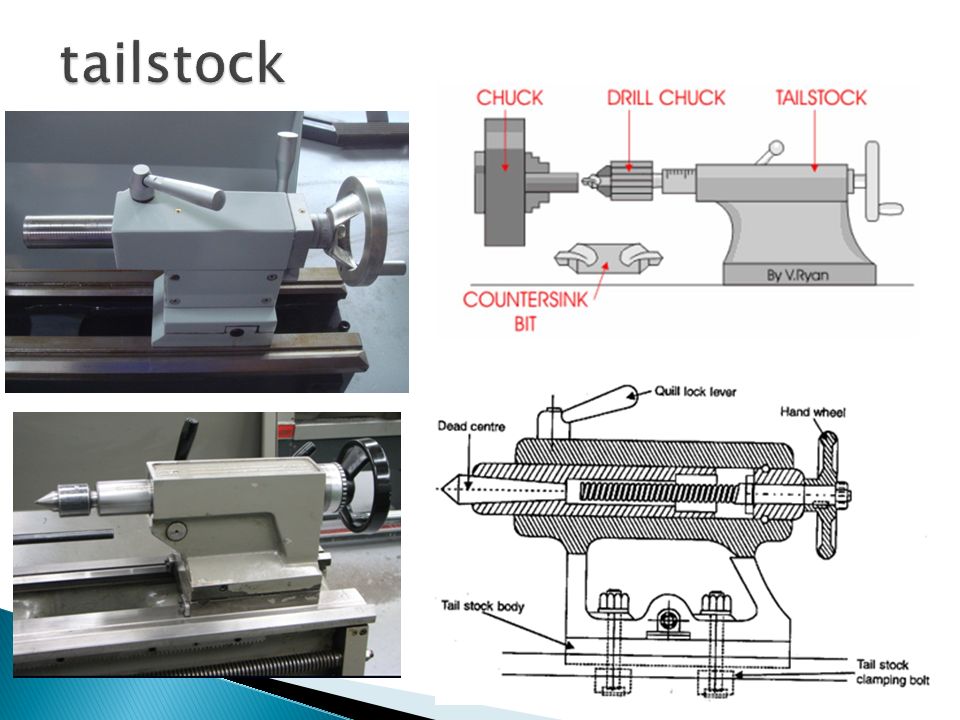
It is movable casting located opposite the headstock on the ways of the bed. It is used for two purposes, (i) to support the other end of the work when being machined, and (ii) to hold a tool for performing operations like drilling, reaming, tapping, etc. It contains the dead centers the adjusting screw and the hand wheel. The body of the tailstock is adjustable on the base which is mounted on the guide ways of the bed and can be moved to and fro. The object of making the body adjustable on the base is provide means for lining up the centre, carried in the moving spindle, with the headstock centre, or for off-setting this centre to permit tapers to be turned.
 to support the other end of the work when being machined, and (ii) to hold a tool for performing operations like drilling, reaming, tapping, etc. It contains the dead centers the adjusting screw and the hand wheel. The body of the tailstock is adjustable on the base which is mounted on the guide ways of the bed and can be moved to and fro. The object of making the body adjustable on the base is provide means for lining up the centre, carried in the moving spindle, with the headstock centre, or for off-setting this centre to permit tapers to be turned..")
15
Axial adjustment of the dead centre in the movable spindle in the tailstock body is provided for by means of a hand-wheel, which is attached to a screw engaging the nuts in the rear of the movable spindle. It can be located by any position in the body by means of a lever. The spindle is bored or ground to a taper gauge to take centre which may be of the fixed or revolving type. The tailstock may be used to hold the dead or ball bearing center or it can be used to hold tapered shank drills, reamers, and drill chucks. The tailstock moves on the ways along the length of the bed to accommodate work of varying lengths. It can be clamped in the desired position by the tailstock clamping nut.

17
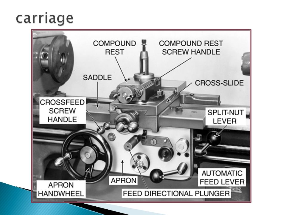
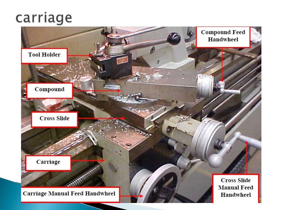
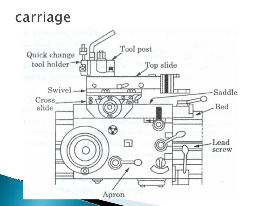
Carriage. It is located between the headstock and the tailstock. It is fitted on the bed and slides along the bed guide ways and can be locked on the bed at any desired position by tightening the carriage lock screw. It can be moved manually with a hand wheel or with power Feed. It consists of following 5 main parts: a) Saddle b) Cross slide c) Compound rest consisting of a swivel and top slide d) Tool post e) Apron
 Saddle b) Cross slide c) Compound rest consisting of a swivel and top slide d) Tool post e) Apron.")
21
It consists of saddle and apron and slides over the ways between the headstock and tailstock. It has the form of letter H and is bridged across the lathe bed to carry the cross slide, compound rest, and tool rest, and is fitted to the outside ways. It also carries the compound rest. The saddle carrying the cross slide and tool post can be locked in any position when carrying out surfacing operation. For turning, the carriage is driven by a feed shaft, which rotates a pinion mounted in a casting at the front of the carriage (apron). This union engages with a rack along the front of the bed, so that it pulls itself and the carriage along the bed.
. This union engages with a rack along the front of the bed, so that it pulls itself and the carriage along the bed..")
22
For screw cutting, the carriage movement is obtained by engaging a split nut over the lead screw which then rotates in relation to the spindle rotation. It provides three movements to the tool: ◦ (i) Longitudinal feed-through carriage movement. ◦ (ii) Cross feed-through cross slide movement. ◦ (iii) Angular feed-through top slide movement
 Longitudinal feed-through carriage movement. ◦ (ii) Cross feed-through cross slide movement. ◦ (iii) Angular feed-through top slide movement.")
24
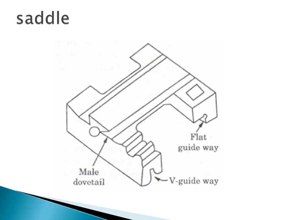
Saddle. It is made up of a H shaped casting. Generally it has a V guide and a flat guide on one side for mounting it on the lathe bed guide ways. It also aids the saddle to slide along the bed guide ways by operating a hand wheel. The other side of saddle is provided with a male dove tail to accommodate the cross slide.

25
It is provided with a female dovetail on one side and assembled on the top of the saddle with its male dovetail. A tapered gib is provided between the saddle and cross slide dovetails to permit required fit for movement of cross slide on saddle. Top surface of cross slide is provided with T slots to enable fixing of rear tool post or coolant attachment. Front side is graduated in degrees to facilitate swiveling of the compound rest to the desired angle.

28
It supports the tool post and cutting tool in its various positions. It may be swiveled on the cross slide to any angle in the horizontal plane its base being graduated suitably. A compound rest is necessary in turning angles and boring short tapers and in turning angles and forms on forming tools. Compound rest consists of swivel and top slide and is mounted on the cross slide. Swivel is directly assembled on the cross slide and can be swiveled on either side to give the desired angle to the compound rest. It is provided with a male dovetail on the top surface. Top slide is provided with a female dovetail and is assembled on the swivel with a tapered jib for adjustments. Top slide can be made to slide on the swivel by a precision screw rod and is moved manually. With the help of the top slide, the tool post can get horizontal, perpendicular, or angular movements to one axis of the bed guide ways depending upon the position of the swivel.

30
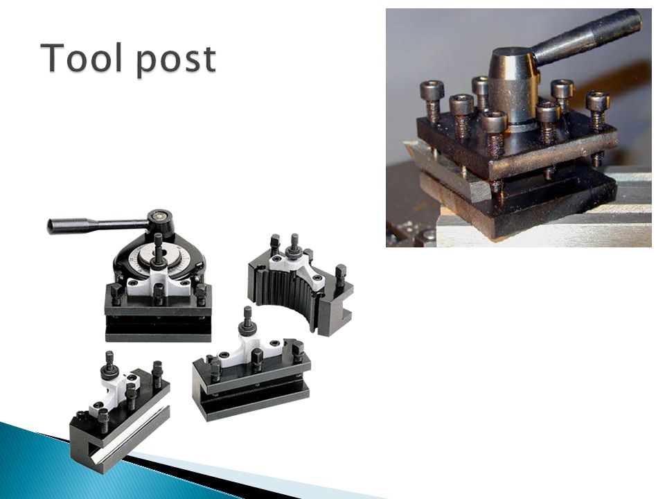
It is used to hold various cutting tool holders. The holders rest on a wedge which is shaped on the bottom to fit into a concave-shaped ring (segmental type), which permits the height of the cutting edge to be adjusted by tilting the tool. It is fixed on the top slide. It gets its movement by the movement of the saddle, cross slide and top slide. Three types of tool posts are commonly used. 1. Ring and rocker tool post. 2. Quick change tool post. 3. Square head tool post.
, which permits the height of the cutting edge to be adjusted by tilting the tool. It is fixed on the top slide. It gets its movement by the movement of the saddle, cross slide and top slide. Three types of tool posts are commonly used. 1. Ring and rocker tool post. 2. Quick change tool post. 3. Square head tool post..")
32
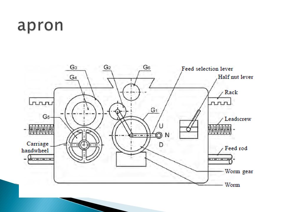
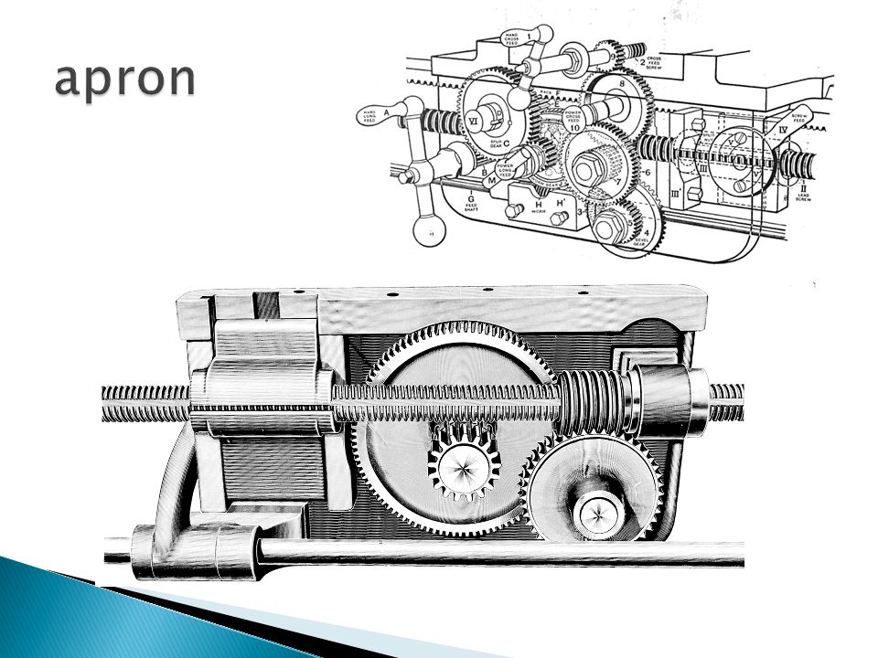
It is fastened to the saddle and hangs over the front of the bed. It contains the gears and clutches for transmitting motion from the feed rod to the carriage, and the split nut which engages with the lead screw during cutting threads. It converts the rotary motion of the feed shaft or the lead screw to a translatory motion of the carriage longitudinally on the bed or of the cross slide transversely on the carriage. The lead screw is coupled to the carriage by means of a split nut fixed in the apron, and the feed-shaft generally drives the carriage through worm gearing. Two types of aprons are extensively used, one type incorporating drop worm mechanism and the other friction or dog clutches

33
The apron is fitted to the front position of the saddle facing the operator. It consists of a hand wheel for saddle movement, pinion to engage with the rack for saddle movement, a lever to engage the automatic feed for the saddle, automatic feed clutch, split nut (half nut), and lead screw. It houses control of carriage and cross slide. It contains controls to transmit motion from the feed rod or lead screw to the carriage and the cross slide. It houses gears, levers, hand wheels and clutches to operate the carriage by hand or by automatic power feed. A lever is provided to engage the split nut for cutting the thread
, and lead screw. It houses control of carriage and cross slide. It contains controls to transmit motion from the feed rod or lead screw to the carriage and the cross slide. It houses gears, levers, hand wheels and clutches to operate the carriage by hand or by automatic power feed. A lever is provided to engage the split nut for cutting the thread.")
36
The movement of tool relative to work piece is called feed. Longitudinal Feed: Tool moves parallel to the work, i.e. towards or away from the headstock. (e.g turning, knurling etc) Cross Feed: Tool moves perpendicular to the work, i.e. towards or away form the operator. Angular Feed: Tool moves at angle to the work, obtained by swiveling the compound rest. Tool is feed by moving carriage and compound rest.
 Cross Feed: Tool moves perpendicular to the work, i.e. towards or away form the operator. Angular Feed: Tool moves at angle to the work, obtained by swiveling the compound rest. Tool is feed by moving carriage and compound rest..")
Similar presentations