Download presentation
Presentation is loading. Please wait.

1
Engine Fuel System (SI Petrol) Fuel Tank – normally positioned in the rear boot area, either under the floor pan for estate cars or over the rear axle for saloons, the latter being a safer position. Should the engine be mounted in the rear, the fuel tank is normally positioned in the front boot area, either over the bulkhead or flat across the boot floor pan, the latter providing more boot space, but is more exposed to danger in a head on crash. The fuel tank made be made from pressed steel and coated inside to prevent corrosion, or a synthetic rubber compound or flame resistant plastic. Inside the fuel tank is normally located the fuel gauge sender unit and electrically driven fuel pump with a primary filter in a combined module. Internal fuel tank baffles are used to prevent fuel surge. The fuel tank is pressurised to about 2 psi to prevent fuel vaporization and pollution. The fuel tank is vented through its own venting system and the engine managements emission control systems again to control pollution. Fuel pipes – These can be made from steel or plastic and are secured by clips at several points along the underside of the vehicle. To allow for engine movement and vibration, rubber hoses connect the pipes to the engine. Later fuel pipes use special connectors which require special tools to disconnect the pipes.

2
Engine Fuel System (SI Petrol) Fuel Filters – to prevent dirt and fluff entering the fuel pump a filter is fitted on the suction side of the pump. On the pressure side of the pump a secondary filter is used, this is a much finer filter in that it prevents very small particles of dirt reaching the carburettor or fuel injection equipment. It should be renewed at the correct service interval as recommended by the manufacturer. When the filter is replaced, it must be fitted in the direction of fuel flow. Air Filters – air cleaners and silencers are fitted to all modern vehicles. Its most important function is to prevent dust and abrasive particles from entering the engine and causing rapid wear. Air filters are designed to give sufficient filtered air, to obtain maximum engine power. The air filter must be changed at the manufactures recommended service interval. The air filter/cleaner also acts as a flame trap and silencer for the air intake system. Fuel Pump – this supplies fuel under high pressure to the fuel injection system, or under low pressure to a carburettor. Carburettor – this is a device which atomizes the fuel and mixes it which the correct amount of air, this device has now been superseded by modern electronic fuel injection.

3
Petrol

4
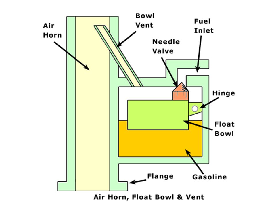
Float chamber (function) – to set and maintain the fuel level within the carburettor, and to control the supply fuel to the carburettor venturi. Operation – when air passes through the venturi due to the engines induction strokes, it creates a depression (suction), around the fuel spray outlet. Atmospheric pressure is acting on the fuel in the float chamber, the difference in theses pressures causes the fuel to flow from the float chamber, through the jet and into the stream. This causes the petrol to mix with the air rushing in to form a combustible mixture. The required air fuel ratio can be obtained by using a jet size which allows the correct amount of fuel to flow for the amount of air passing through the Defects of the simple carburettor. As engine speed increases, air pressure and density decreases i.e. the air gets thinner, however the quantity of fuel increases i.e. greater pressure exerted on the fuel, this causes the air/fuel mixture to get progressively richer (to much fuel). As the engine speed decreases, the air/fuel mixture becomes progressively weaker. Some form of compensation is therefore required so that the correct amount of air and fuel is supplied to the engine under all operating conditions.
, around the fuel spray outlet. Atmospheric pressure is acting on the fuel in the float chamber, the difference in theses pressures causes the fuel to flow from the float chamber, through the jet and into the stream. This causes the petrol to mix with the air rushing in to form a combustible mixture. The required air fuel ratio can be obtained by using a jet size which allows the correct amount of fuel to flow for the amount of air passing through the Defects of the simple carburettor. As engine speed increases, air pressure and density decreases i.e. the air gets thinner, however the quantity of fuel increases i.e. greater pressure exerted on the fuel, this causes the air/fuel mixture to get progressively richer (to much fuel). As the engine speed decreases, the air/fuel mixture becomes progressively weaker. Some form of compensation is therefore required so that the correct amount of air and fuel is supplied to the engine under all operating conditions..")
5
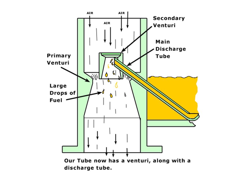
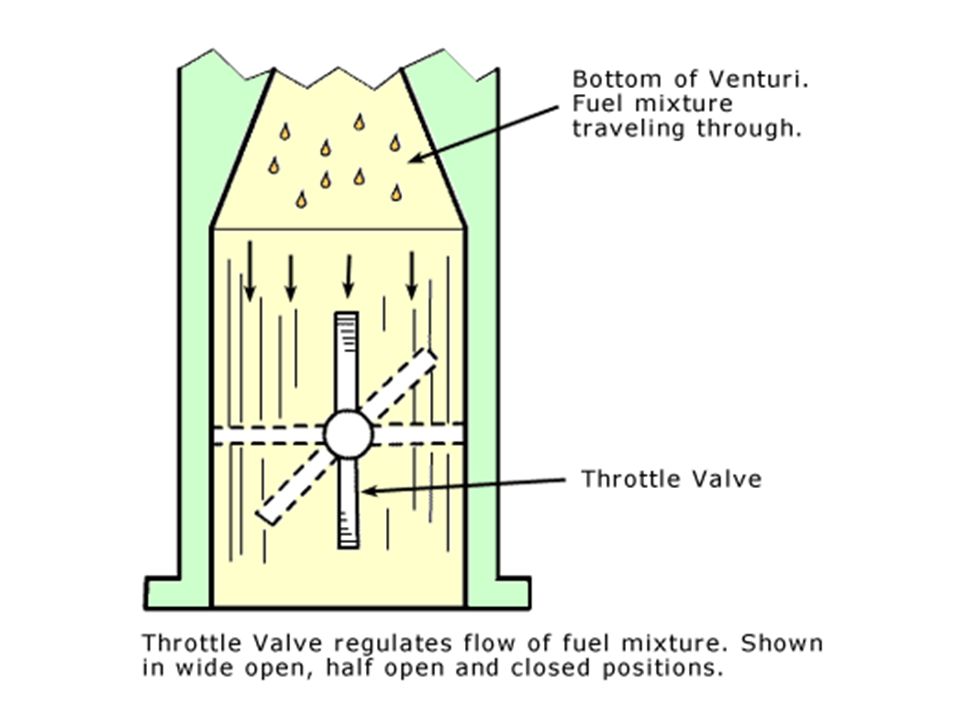
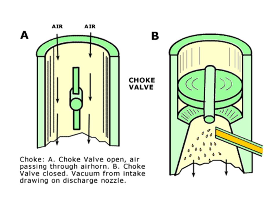
Petrol Operation of the Venturi The Choke Valve is used to provide a rich air/fuel ratio for cold starting Choke Valve closed The Float Chamber The Throttle Valve controls the amount of air fuel mixture entering the engine and therefore engine power The Simple Carburettor

10
Air Fuel Ratio Fuel mixture strengths – petrol will not burn unless it is mixed with air, to obtain the best possible combustion of the fuel, which should result in good engine power and fuel consumption and low emissions (pollution), the air fuel ratio must be chemically correct i.e. the right amount of air and fuel must be mixed together to give an air fuel ratio of 14.7 to 1 by mass. This is referred to as the shoitcmetreic air fuel ratio, this ratio can also be describe by the term Lambda. Lamba is the Greek word meaning ‘air’. When their is more air present than fuel in the air fuel mixture, it is said to be ‘weak’ or ‘lean’ i.e. not enough fuel e.g. a ratio of 25 to 1, this results in a Lambda reading of more than 1.When their is not enough air present, the mixture is referred to as ‘rich’ e.g. a air fuel ratio of 8 to 1, in this case Lambda equals less than 1. Weak/lean air/fuel mixtures – can result in low fuel consumption, low emissions (pollution), however, weak air fuel mixtures can also result in poor engine performance (lack of power) and high engine temperatures ( because the fuel burns more slowly) Rich air/ fuel mixtures – can result in greater engine power, however this also results in poorer fuel consumption and greatly increased emissions (pollution)
, however, weak air fuel mixtures can also result in poor engine performance (lack of power) and high engine temperatures ( because the fuel burns more slowly) Rich air/ fuel mixtures – can result in greater engine power, however this also results in poorer fuel consumption and greatly increased emissions (pollution).")
11
Engine S I Fuel System ECU – Electronic control unit. This contains a computer which takes information from sensors and controls the amount of fuel injected by operating the injectors for just the right amount of time. Air flow/mass meter – A sensor used to tell the ECU how much air is being drawn into the engine. MAP sensor – Manifold absolute pressure sensor. This senses the pressure in the engines inlet manifold, this gives an indication of the load the engine is working under. Speed/crankshaft sensor – This tells the ECU has fast the engine is rotating and sometimes the position of the crankshaft. Temperature sensor – Coolant temperature is used determine if more fuel is needed when the engine is cold or warming up. Lambda sensor – A sensor located in the exhaust system which tells the ECU the amount of oxygen in the exhaust gases, form this the ECU can determine if the air/fuel ratio is correct. Fuel pump – A pump, normally located in the fuel tank, which supplies fuel under pressure to the fuel injectors.

12
Engine S I Fuel System Fuel filter – keeps the fuel very clean to prevent the injectors becoming damaged or blocked. Fuel rail – A common connection to multi point injectors, acts a reservoir of fuel (small tank of fuel). Injector – A electrical device which contains a winding or solenoid. When turned on by the ECU, the injector opens and fuel is sprayed into the inlet manifold, or into the combustion chamber itself. Idle actuator – A valve controlled by the ECU which controls the idle speed of the engine. ECU – Electronic Unit. This contains a computer which takes information from sensors and controls the amount of fuel injected by operating the injectors for just the right amount of time. The ECU also controls the operation of the ignition and the other engine rated systems.
. Injector – A electrical device which contains a winding or solenoid. When turned on by the ECU, the injector opens and fuel is sprayed into the inlet manifold, or into the combustion chamber itself. Idle actuator – A valve controlled by the ECU which controls the idle speed of the engine. ECU – Electronic Unit. This contains a computer which takes information from sensors and controls the amount of fuel injected by operating the injectors for just the right amount of time. The ECU also controls the operation of the ignition and the other engine rated systems..")
13
Typical Fuel System Components that supply clean fuel to the fuel metering system (fuel pump, fuel pipes, fuel filters). 1. Fuel Supply System Components that supply controlled clean air to the engine (air filter, ducting, valves). 2. Air Supply System Components that meter the correct amount of fuel (and air) entering the engine (injectors, pressure regulator, throttle valve). 3. Fuel Metering System The exact components used will vary with fuel system type and design. 13 of 14
. 2. Air Supply System Components that meter the correct amount of fuel (and air) entering the engine (injectors, pressure regulator, throttle valve). 3. Fuel Metering System The exact components used will vary with fuel system type and design. 13 of 14.")
14
Introduction to Electronic Petrol Throttle/Single Point Fuel Injection Systems 14 of 14 The Carburettor has now been replaced with petrol injection systems. These systems supply the engine with a highly atomized mixture of air and fuel in the correct air/fuel ratio. This has the following advantages over the carburettor systems Lower exhaust emissions (pollution) Better fuel consumption Smoother engine operation and greater power Automatic adjustment of the air/fuel ratio to keep the vehicles emissions (pollution) to a minimum.
 Better fuel consumption Smoother engine operation and greater power Automatic adjustment of the air/fuel ratio to keep the vehicles emissions (pollution) to a minimum..")
15
Air drawn in by the engine Fuel Supply Throttle Body Throttle Valve Inlet Manifold Fuel Injector (one off) The Engine Throttle Body/Single Point S.I. Fuel Injection

16
Single Point Electronic Fuel Injection (EFI) Systems EFI systems are classified by using the point of injection. A fuel injector (may be 2) is located in a throttle body assembly that sits on top of the inlet manifold. Fuel is sprayed into the inlet manifold from above the throttle valve, mixing with incoming air. Fuel quantity, how much feul is injected is controlled by an ECU. Single Point (Throttle Body) Fuel Injection 16 of 14 ECU Fuel in Inlet manifold Air in TB injector
 is located in a throttle body assembly that sits on top of the inlet manifold. Fuel is sprayed into the inlet manifold from above the throttle valve, mixing with incoming air. Fuel quantity, how much feul is injected is controlled by an ECU. Single Point (Throttle Body) Fuel Injection 16 of 14 ECU Fuel in Inlet manifold Air in TB injector.")
17
Needle valve Electrical connector Fuel filter Fuel in Spring Armature Nozzle/jet Solenoid coil Electronic Fuel Injector Operation An injector sprays fuel into the inlet manifold by use of a solenoid coil. When the coil is switch on by the ECU, it pulls the armature/needle valve away from the nozzle, allowing pressurized fuel into the engine. When the coil is not switched on, the spring pushes the armature/needle against the nozzle, no fuel is injected into the inlet manifold Injectors are more precise and efficient than carburettors.

18
The ECU (Brain) receives Information from varies sensors. From this information it works out how much fuel the engine needs Inputs Outputs Single Point Injection Sensor

19
Air drawn in by the engine Fuel Injectors Throttle Valve Fuel Supply Inlet Manifold Injectors Engine Multi – Point S.I. Fuel Injection

20
Typical S.I. Fuel System Layout (Simplified) Fuel Tank Fuel Pump Fuel Filters Carburettor Or Single Point Throttle Body Housing Fuel Injector or Carburettor Venturi Fuel Not used is returned to the fuel tank Inlet Manifold Engine Combustion Chamber Fuel Pressure Regulator EFI Only
 Fuel Tank Fuel Pump Fuel Filters Carburettor Or Single Point Throttle Body Housing Fuel Injector or Carburettor Venturi Fuel Not used is returned to the fuel tank Inlet Manifold Engine Combustion Chamber Fuel Pressure Regulator EFI Only.")
Similar presentations


>")


 IGNITION SYSTEM DISTRIBUTORLESS IGNITION SYSTEM.>")


>")