Download presentation
Presentation is loading. Please wait.

1
THERMAL AND CHEMICAL TECHNOLOGIES OF NONWOVENS PRODUCTION
Klára Kalinová Katedra netkaných textilií

2
Lectures 1 definition of NW, productivity of NW, bicomponent fibers, thermal constants, shrinking and degradation of polymers 2 DSC, DTA, TMA, thermoelectric couples, chemical binders 3 crosslinking of polymers, binder properties, coagulation, wet-laid 4 spunbond (SB) 5 meltblown (MB) 6 flashspinning, SB, MB modifications, typical product of SB and MB, electrostatic spinning 7 Solution spinning, thermal flow, types of fibers for thermo-bonding 8 powder bonding, through air thermobonding, calendering 9 modified rollers for prevention of their deformation, ultrasound bonding, infrared bonding, microwave bonding 10 radio-frequency bonding, thermal constants of polymers, dispersion, print bonding, spray bonding, froth bonding 11 saturation bonding, felting, thermoplastic adhesives for laminating, hot-melt shapes, hot-melt applicators 12 coating and laminating
 5 meltblown (MB) 6 flashspinning, SB, MB modifications, typical product of SB and MB, electrostatic spinning. 7 Solution spinning, thermal flow, types of fibers for thermo-bonding. 8 powder bonding, through air thermobonding, calendering. 9 modified rollers for prevention of their deformation, ultrasound bonding, infrared bonding, microwave bonding. 10 radio-frequency bonding, thermal constants of polymers, dispersion, print bonding, spray bonding, froth bonding. 11 saturation bonding, felting, thermoplastic adhesives for laminating, hot-melt shapes, hot-melt applicators. 12 coating and laminating.")
3
Definition of nonwovens
NONWOVENS IN GENERAL Definition of nonwovens Nonwoven is a sheet, web, or batt of natural and/or man-made fibers or filaments, excluding paper, that have not been converted into the yarns, and that are bonded to each other by any of several means...

4
1. To distinguish nonwovens from papers, a material shall be defined as a nonwoven if:
a) More than 50% by mass of its fibrous content is made up of fibers (excluding chemically digested vegetable fibers) with a length to diameter ratio greater than 300; or b) More than 30% by mass of its fibrous content is made up of fibers as in “a” above and meets one or both of the following criteria: i. Length to diameter ratio mare than 600. ii. Density of the fabrics is less than 0.4 g/cm3. 2. Bonding methods may include any of the following means or any combination thereof, including but not limited to: a) Adding and adhesive. b) Thermally fusing the fibers or filaments to each other or to other meltable fibers or powders. c) Fusing fibers by first dissolving, then reinforcing their surfaces. d) Creating physical tangles among the fibers. e) Stitching the fibers or filaments in place. 3. A nonwoven may be a structural component of a composite. 4. Nonwoven structures may incorporate monofilaments or yearns.
 More than 50% by mass of its fibrous content is made up of fibers (excluding chemically digested vegetable fibers) with a length to diameter ratio greater than 300; or. b) More than 30% by mass of its fibrous content is made up of fibers as in a above and meets one or both of the following criteria: i. Length to diameter ratio mare than 600. ii. Density of the fabrics is less than 0.4 g/cm3. 2. Bonding methods may include any of the following means or any combination thereof, including but not limited to: a) Adding and adhesive. b) Thermally fusing the fibers or filaments to each other or to other meltable fibers or powders. c) Fusing fibers by first dissolving, then reinforcing their surfaces. d) Creating physical tangles among the fibers. e) Stitching the fibers or filaments in place. 3. A nonwoven may be a structural component of a composite. 4. Nonwoven structures may incorporate monofilaments or yearns.")
5
Production of nonwovens
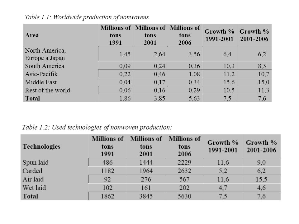
The world production of nonwovens during the year of 2001was 3,85 millions of tons, i.e. 93 milliards of square meters worth more then 14 milliards of dollars. During the years of , the growth rates of nonwoven production achieve 7,5 % worldwide. The worldwide production in the different areas of world including estimated progression by the year 2006 [Study Examines Nonwovens’ Past and Future, new INDA report..., Nonwovens Industry 33 (2002), 4, pp ]: The total world production is shown in Tables
, 4, pp ]: The total world production is shown in Tables.")
7
The spun laid (spun bond and melt blown) and air laid present the most of technological expansions. In the year 2000, the spun bond technology achieved 50% of European nonwoven production. Renascence of air laid technology is due to high production rate, low costs and uniform products. Reduced chemical bonding technology caused less growth rate of carded technology. Stitch bonding technology evolves successfully. The growth rates of nonwoven production are extremely high when compared with any other industry.

9
POLYMERIC AND FIBROUS PROPERTIES WITH RESPECT TO THERMAL PROCESS
Bicomponent fibers - Side-by-side fibers Side-by-side fibers are usually used as self-bonding fibers. Bicomponent fiber is created by two polymers within a filament having a different strain level or shrinkage tendency. Higher processing speeds, reduced equipment cost, more bulk and improved continuity of process are among the advantages seen with this technology.

10
Bicomponent fiber. Sheath/core 50/50 PE/PP.
− A first type of sheath/core is self-bonding fibers consisting of a low melting temperature sheath and a higher melting temperature core. Common sheath/core alternatives in such applications include PE/PP, PE/PET, Co-PET/PET, and PP/PET. These products are used in 100% form as well as in blends with homopolymer filaments. − A second type of sheath/core is filled fibers consisting of a core product produced form recycled material, conductive material or other material that is covered by a sheath that possesses desired aesthetics or other properties. − A third type of sheath/core is a sheath polymer containing expensive additives or other attributes primarily useful on the surface of filaments.

11
Microfibers can be produced by bicomponent techniques in which the fibers are either caused by split, or one of the two components is dissolved or melted away. These techniques have long been known to be capable of producing much smaller fibers than with homopolymer techniques. Some examples of such fibers are: − Filaments consisting of alternating segments (pies or stripes) of two different polymers that break apart during downstream processing. − Filaments consisting of a sea component and an island component, with the sea component dissolved or melted away in subsequent processing. These products have usually been staple fibers with the sea dissolved away in non-woven fabrics. The use of hydroentangling to break the islands apart from the sea also offers promising potential. Islands in a sea.
 of two different polymers that break apart during downstream processing. − Filaments consisting of a sea component and an island component, with the sea component dissolved or melted away in subsequent processing. These products have usually been staple fibers with the sea dissolved away in non-woven fabrics. The use of hydroentangling to break the islands apart from the sea also offers promising potential. Islands in a sea.")
12
Mixed fibers Examples of some applications include the following: − Color mixes to produce desired aesthetics. − Denier and cross-section mixes to produce higher bulk or other desired aesthetics. − Mixes of homopolymer filaments with bicomponents at varying levels to control certain fabric properties such as bonding strength. Some useful results are also being obtained by mixing of bicomponent cross-sections to obtain specific fiber or fabric properties. Tipped yarns Tipped products are used to produce special aesthetics, bonding, or other properties.

13
Thermal constants - The important thermal constants are temperatures between two physical states of polymers; i.e. Physical states of polymers. Tg is glass temperature and Tf is plastic flow temperature.

14
Glass temperature Tg. Below this temperature, the polymer is hard, fragile and less deformable. The product lying in the glass state loses textile character. It is why the choosing of polymer is dependent on Tg that shall be lower than the production temperature. Till seventieth years, the mixture of polymers with softening agents solved this problem. The softening agents were chemicals lowering concentration of secondary bonds between macromolecules and Tg respectively. They were aggressive chemicals that ejected from the polymer to ambient. Due to copolymers a lot of bonding agents with low Tg is available. Plastic flow temperature Tf. Tf sets the minimal melting temperature. Tf can be above decomposition temperature and polymer is not useable. The depolymerization, oxidation and other chemical reactions can proceed in the melting.

15
Viscosity is a function of temperature and polymerization degree.
− Specific Heats csp of polymers set heat consumption during the polymer heating. − Latent heat cl of crystallite fusion can be utilized to crystallinity degree assessment.

16
Fibrous thermo-shrinking
Due to the heat, intermolecular bindings of drown fibers release and macromolecules create statistical coil then they change their long. This process calls shrinking. Shrinking degree in percents is given by follows: 1. Fiber history: type of polymer, molecular weight, spinning condition, drawing ratio, rate and temperature of drawing, heat fixing, storage time and conditions. 2. Temperature of shrinking 3. Shrinking time 4. Shrinking medium (water, air, etc.) 5. Tension during the shrinking Then, the folow parameter can be measured. 1. Shrinking degree (%) 2. Shrinking force 3. Shrinking rate
 5. Tension during the shrinking. Then, the folow parameter can be measured. 1. Shrinking degree (%) 2. Shrinking force. 3. Shrinking rate.")
17
Thermal degradation of polymers
Solar radiation, temperature, precipitation and oxygen give a start to an ageing process of the materials, influencing at the same time many of their physical properties. These processes are inevitable in time and are thus simulated by the XENOTEST, an apparatus for accelerated exposure to light and bad weather. With this apparatus we can make 2 kinds of tests: the first one, called "exposure to the light", simulating the solar effect behind windows, while the second one, called "solidity to the bad weather", simulates the effect of the sun outdoors. The artificial bad weather simulated by the XENOTEST offers the advantage of well-defined conditions that can be regulated and repeated at any moment. A xenon-radiating instrument produces the radiation that strikes the surface of the test-piece. The temperature can be regulated up to a maximum of 90°C and the humidity can reach 95%. The rain is simulated by a spray system, while a timer allows us to plan different rain cycles. The leather test-piece is inserted in the XENOTEST together with a blue scale, made of eight standards of coloured wool. Fastness is valued in this way: when the first perception of a chromatic variation of the test-piece appears, we check if the contrast between the exposed zone and that not exposed is equal to the 4° standard of the gray scale for assessing change of colour. When the chromatic difference is actually equal to the 4° standard of the gray scale, the test is over.

18
Detection of polymeric structural changes and thermal constants
DSC method The operation of a Differential Scanning Calorimeter (DSC) is based on measurement of the thermal response of an unknown specimen as compared with a standard when the two are heated uniformly at a constant rate. The DSC consists of a furnace containing two identical crucibles, each of which rests on a thin plate located inside the measurement head. Directly beneath the center of each crucible is the junction of a differential thermocouple. Any difference in temperature of the two specimens is caused by differences in mass, specific heat, heats of reaction, or phase transitions.
 is based on measurement of the thermal response of an unknown specimen as compared with a standard when the two are heated uniformly at a constant rate. The DSC consists of a furnace containing two identical crucibles, each of which rests on a thin plate located inside the measurement head. Directly beneath the center of each crucible is the junction of a differential thermocouple. Any difference in temperature of the two specimens is caused by differences in mass, specific heat, heats of reaction, or phase transitions.")
19
DSC measurement arrangement
The DSC consists of a furnace containing two identical crucibles, each of which rests on a thin plate located inside the measurement head. Directly beneath the center of each crucible is the junction of a differential thermocouple. Differential Scanning Calorimeter (DSC) measures the amount of energy (heat) absorbed or released by a sample as it is heated, cooled, or held at a constant temperature. Typical applications include determination of melting point temperature and the heat of melting; measurement of the glass transition temperature; curing and crystallization studies; and identification of phase transformations.
 measures the amount of energy (heat) absorbed or released by a sample as it is heated, cooled, or held at a constant temperature. Typical applications include determination of melting point temperature and the heat of melting; measurement of the glass transition temperature; curing and crystallization studies; and identification of phase transformations.")
20
To determine specific heat capacity, a baseline is established by measuring the temperature difference of the two empty crucibles as the temperature is changed at a constant rate over the temperature range of interest. Thermal response records are then acquired for a standard material (usually sapphire) and an unknown under identical conditions. The ratio of the departure of the standard and unknown from the baseline is then used to calculate the specific heat of the unknown. The DSC is used to measure specific heat capacity (100 to 1200oC) and heats of transition as well as to detect the temperature of phase changes and melting points in the range of 20 to 1500oC. Specific heat capacity can be used in conjunction with thermal diffusivity to obtain thermal conductivity.
 and heats of transition as well as to detect the temperature of phase changes and melting points in the range of 20 to 1500oC. Specific heat capacity can be used in conjunction with thermal diffusivity to obtain thermal conductivity.")
21
DTA method The DTA uses a dynamic measuring principle. It can measure endothermal and exothermal heat flows between the sample and the reference. These heat flows are result of physical or chemical changes of the samples. Very often a DTA is used for purity measurements of mixtures of metals. This is due to the fact that the melting point changes in dependence to differing amounts of impurities. The DTA 404 PC Eos allows determination of such effects between room temperature and 1550°C. Using true state-of-the-art DSC sensors, quantification of transformation energetics is also possible. Incorporating a newly designed electronics and data acquisition system, the DTA 404 PC Eos gives excellent performance at a very attractive price. It is an ideal instrument for research, development and quality control. Analysis of Phase transition temperatures Transition enthalpies Glass transitions Crystallisation behavior Decomposition behavior Phase diagrams Influence of additives Reaction kinetics

22
DTA diagram. T0 is opening temperature, Tm maximal or minimal temperature, T1 temperature of return to zero line, Tx temperature of exothermic process start, Ty temperature of exothermic process end

23
TMA method Thermomechanical Analyzer (TMA) is a computer-controlled laboratory instrument for use in a broad range of application areas. The TMA permits the measurement of dimensional and viscoelastic changes as a function of temperature or time. Typical applications include coefficient of expansion, softening point, glass transition determinations, and modulus measurements.
 is a computer-controlled laboratory instrument for use in a broad range of application areas. The TMA permits the measurement of dimensional and viscoelastic changes as a function of temperature or time. Typical applications include coefficient of expansion, softening point, glass transition determinations, and modulus measurements.")
24
TMA diagram. The conventional TMA curve (L) is simply a moving average of the length change over one period. The reversing thermal expansivity (α) is derived from the ratio of the amplitudes of the length change and temperature change using a discrete Fourrier transform. The total rate of length change (dL/dT [300 parts per milion = 0,03%]) is simply the derivative of the average length with respect to temperature. As with MT-DSC there is a time lag between the temperature change and the sample response (δ).
 is simply a moving average of the length change over one period. The reversing thermal expansivity (α) is derived from the ratio of the amplitudes of the length change and temperature change using a discrete Fourrier transform. The total rate of length change (dL/dT [300 parts per milion = 0,03%]) is simply the derivative of the average length with respect to temperature. As with MT-DSC there is a time lag between the temperature change and the sample response (δ)..")
25
TMA instrument In this technique (TMA), dimensional changes in a sample are the primary measurement, while the sample is heated, cooled, or studied at a fixed temperature. A simple schematic figure of a typical TMA instrument is shown below.
, dimensional changes in a sample are the primary measurement, while the sample is heated, cooled, or studied at a fixed temperature. A simple schematic figure of a typical TMA instrument is shown below.")
26
The sample sits on a support within the furnace
The sample sits on a support within the furnace. The changes in length are measured by a sensitive position transducer. A thermocouple near the sample indicates its temperature. The gas atmosphere through the instrument prevents oxidation and also assists in heat transfer to the sample. Helium is effective in this respect. The load may be applied by static weights, or by a force motor. The applied load can be programmed to allow a greater range of experiments. The instrument is calibrated for position measurements by heating a sample whose expansion coefficient is accurately known. Aluminium is commonly used, in the form of small machined blocks or cylinders. Sample sizes are commonly around 5-10 mm in height and width. It is important to prepare samples with clean, flat and parallel faces to avoid artefacts in the recorded curves. There are a number of approaches to temperature calibration. One method uses small flat pieces of pure metals, e.g. indium, sandwiched between thin discs of quartz glass. Melting of the metal sandwich under the probe with a moderate load results in a sharp displacement of the probe. With care, a multi-layer sandwich can be built up using "fillings" of different metals, so that a multi-point calibration can be obtained in one experiment.

27
Sometimes the required information is about the deformation of the sample, and several types of probe are used for different types of study. A range of typical probes, available with most instruments, is shown below

28
Heat flow sensors- Thermoelectric couples
Heat flow sensors- thermometers Dilatation thermometer Gas expansion thermometer Resistance thermometer Radiation thermometer ...

29
POLYMERIC AND FIBROUS PROPERTIES WITH RESPECT TO CHEMICAL PROCESS
Dispersion Polymer dispersion in water stabilized by an anionic surfactant.

30
There are three main kinds of binders: butadiene copolymers, acrylates, and vinyl copolymers. The chemical compositions influence Tg, hardness and softness, hydrophobicity and hydrophilicity, elasticity, aging, and dry tensile strength of binders. The higher the Tg, the stiffer the hand and higher the dry tensile strength of binders. The lower the (Tg) of the monomer units, the softer is the resulting polymer. A sampling of the most common monomers used in the manufacture of latex polymer for nonwoven binders include the following materials: Monomer Tg(0C) Ethylene Butadiene - 78 Butyl Acrylate - 52 Ethyl Acrylate - 22 Vinyl Acetate + 30 Vinyl Chloride + 80 Methyl Methacrylate Styrene Acrylonitrile
 of the monomer units, the softer is the resulting polymer. A sampling of the most common monomers used in the manufacture of latex polymer for nonwoven binders include the following materials: Monomer Tg(0C) Ethylene Butadiene Butyl Acrylate Ethyl Acrylate Vinyl Acetate Vinyl Chloride Methyl Methacrylate Styrene Acrylonitrile")
31
Polymer and co-polymer dispersions
The butadiene polymers are cross-linked by polysulphides, and their properties are modified by different copolymers. The butadiene monomers provide elasticity while styrene and acrylonitrile monomers give tensile strength, and oil and solvent resistance, respectively. Their disadvantages are oxidation and discoloration due to residual double bonds in their polymer chains. where Φ denotes a phenyl group Styrene/Butadiene Rubber (SBR) Butadiene/Acrylonitrile Rubber (NBR)
 Butadiene/Acrylonitrile Rubber (NBR)")
32
Acrylic binders are the most widely used and versatile binders available with various modifications. The properties of acrylic binders differ according to their derivatives and copolymers. They are frequently copolymerized with styrene, acrylonitrile, vinyl chloride or vinyl acetate, depending on the desirable properties. Some of these properties are hardness from styrene, solvent resistance from acrylonitrile, flame retardancy from vinyl chloride, and cost benefits from vinyl acetate. The functionality of binders is in the functional groups attached to polymer chains, which influences wet and solvent properties. To modify binder properties, copolymerization with a small amount of monomers with special functionality is performed. The main functionalities in binders are carboxyl and amide side chains. The carboxyl functionality is related to binders which contain acrylic acid or methacrylic acid by copolymerization. The binders are crosslinkable since the functional group, carboxylic acid, provides sites for crosslinking reactions.

33
Acrylic Acid Derivatives - structural elements
Acrylates Acrylic Acid Acrylamide Metholyated Acrylaminde

34
Vinyl copolymers are two main binders for vinyl copolymers: vinyl chloride and vinyl acetate. Since the vinyl binders are stiff, they are plasticized externally or internally. As internal plasticizers, ethylene and acrylate monomers are used, and external plasticizers consist of vinyl chloride. Due to its low Tg, vinyl acetate is not that stiff, and its advantage is low cost. The chlorides cause yellowing problems. The chemical structures are closely related Tg and stiffness of binders. Vinyl acetate Vinyl chloride

35
Crosslinking of polymers
Vulcanization of diens Vulcanization is the process of cross-linking elastomer molecules to make the bulk material harder, less soluble and more durable. The finished product is not sticky like raw rubber, does not harden with cold or soften much except with great heat, is elastic, springing back into shape when deformed instead of remaining deformed as unvulcanized rubber does, is highly resistant to abrasion and to gasoline and most chemicals, and is a good insulator against electricity and heat. Many synthetic rubbers undergo processes of vulcanization, some of which are similar to that applied to natural rubber. Vulcanization of diens

36
Crosslinking with Organic Peroxide
Crosslinking reaction starts at high temperatures, and it brings to the formation of a three dimensional network by creating bonds between the polymer chains. Peroxide crosslinking may happen in a temperature range varying from 110 to more than 200°C and leads to carbon-to-carbon bonds creation by hydrogen abstraction from the polymer chain. Crosslinking reaction steps are : Step 1) Peroxide thermal decomposition
 Peroxide thermal decomposition.")
37
Step 2) Hydrogen abstraction with radical formation on the polymer chain
 Hydrogen abstraction with radical formation on the polymer chain")
38
Step3) Crosslinking reaction by free macroradical recombination
 Crosslinking reaction by free macroradical recombination")
39
Carboxyl functionality
This functionality is related to binders which contain acrylic acid or methacrylic acid by copolymerization. The binders are crosslinkable since the functional group, carboxylic. Carboxy-groups with ZnO: Carboxy-groups with ZnO

40
The binders containing the substituted acrylamide groups have self-crosslinking properties and the possible reaction as follows:

41
The following comparison of latex binder chemical types provides an indication of the relative performance, as well as the advantages and disadvantages of each type of binder. As indicated, the binder properties can be modified considerably by the presence of co-monomers. Acrylic: These binders offer the greatest durability, color stability, and dry/wet performance. Acrylic binders have the widest range of fabric hand properties. They can be formulated to vary from very soft (Tg = -40oC) to extremely hard (Tg = 105oC). These binders can be used in virtually all nonwovens applications, although they tend to be more costly. These polymers can be made to cross-link, with substantial improvement in durability. Styrenated Acrylics: These are tough, hydrophobic binders. The resulting textile hand ranges from soft-to-firm (Tg varies from –20oC to +105oC ).These binders can be used in applications where there is a need for some wet strength without crosslinking. The use of this type of latex binder does involve some sacrifice in UV and solvent resistance. Vinyl Acetate (VAC): The vinyl acetate binders are firm (Tg = +30oC to +40oC); however, they are relatively low cost and find extensive use. They offer good dry strength and toughness, but are somewhat hydrophilic and have a tendency to yellow when subjected to heat. Vinyl Acrylics: These binders are more hydrophobic than the straight VAC binders. They provide excellent toughness, flexibility, and better color stability. They are the compromise between VAC and acrylic, and can compete on a cost/performance basis. The hand range is limited to intermediate softness (Tg = -10oC) to a firm hand (Tg = +30oC).
 to extremely hard (Tg = 105oC). These binders can be used in virtually all nonwovens applications, although they tend to be more costly. These polymers can be made to cross-link, with substantial improvement in durability. Styrenated Acrylics: These are tough, hydrophobic binders. The resulting textile hand ranges from soft-to-firm (Tg varies from –20oC to +105oC ).These binders can be used in applications where there is a need for some wet strength without crosslinking. The use of this type of latex binder does involve some sacrifice in UV and solvent resistance. Vinyl Acetate (VAC): The vinyl acetate binders are firm (Tg = +30oC to +40oC); however, they are relatively low cost and find extensive use. They offer good dry strength and toughness, but are somewhat hydrophilic and have a tendency to yellow when subjected to heat. Vinyl Acrylics: These binders are more hydrophobic than the straight VAC binders. They provide excellent toughness, flexibility, and better color stability. They are the compromise between VAC and acrylic, and can compete on a cost/performance basis. The hand range is limited to intermediate softness (Tg = -10oC) to a firm hand (Tg = +30oC).")
42
Ethylene Vinyl Acetate (EVA): These latex binders have a (Tg range of –20oC to +115oC, which is equivalent to soft ranging to an intermediate textile hand. They exhibit high wet strength, coupled with excellent absorbency. In general, they are less costly than acrylics. They do have a tendency to have more of an odor compared to other binders. They are used primarily in wipes, air-laid pulp fabrics and similar applications. Styrene-Butadiene (S/B, SB, or styrene butadiene rubber): These binders have an excellent combination of flexibility and toughness. They range in hardness from very soft (Tg = -30oC) to very firm (Tg = +80oC). However, the (Tg of an SB binder is not strictly comparable to other classes of nonwoven binders. The styrene-to-butadiene ratio (S/B ratio) is the most common method for describing the relative hand resulting from the use of these binders. The higher the styrene content, the firmer the hand. When cross-linked, this class of binder is very hydrophobic and durable. They are affected somewhat by heat and light because of their tendency to oxidize.
: These binders have an excellent combination of flexibility and toughness. They range in hardness from very soft (Tg. = -30oC) to very firm (Tg = +80oC). However, the (Tg of an SB binder is not strictly comparable to other classes of nonwoven binders. The styrene-to-butadiene ratio (S/B ratio) is the most common method for describing the relative hand resulting from the use of these binders. The higher the styrene content, the firmer the hand. When cross-linked, this class of binder is very hydrophobic and durable. They are affected somewhat by heat and light because of their tendency to oxidize.")
43
Polyvinyl Chloride (PVC): The homopolymer of polyvinyl chloride is a very hard, rigid polymer (Tg = +80oC). This polymer must be plasticized to provide flexibility and film-forming properties. Normally, the (PVC) binders used in nonwovens are softened internally by co-polymerizing the vinyl chloride or with softer acrylic monomers. The hand range of most of these polymers is still relatively firm (Tg is greater than the +30oC). Because this type of polymer is quite thermoplastic, it performs well in heat and dielectric sealing applications. This can be an advantage in some uses. Also, the chlorine content of the polymer promotes flame retardancy. This feature is one of the primary benefits of utilizing this type of binder. However, the chlorine also conveys the tendency to yellow upon heat aging, due to elimination of hydrogen chloride from the polymer. Ethylene/Vinyl Chloride (EVCI): Binders in this class have a slightly broader hand range (Tg = OoC to +30oC) without the external plasticization required of (PVC) binders. The presence of the chlorine again conveys some flame retardancy. These binders exhibit good acid resistance, fair water resistance, and excellent adhesion to synthetic fibers. There is some tendency to yellow upon aging. In essence, this is an internally plasticized (PVC) binder, considering the ethylene monomer to be the softener.
: Binders in this class have a slightly broader hand range (Tg = OoC to +30oC) without the external plasticization required of (PVC) binders. The presence of the chlorine again conveys some flame retardancy. These binders exhibit good acid resistance, fair water resistance, and excellent adhesion to synthetic fibers. There is some tendency to yellow upon aging. In essence, this is an internally plasticized (PVC) binder, considering the ethylene monomer to be the softener.")
44
Coagulation Coagulation is impossible, when there is no interaction between two particles. The trajectories of the particles can be divided into `open' and `closed' ones, separated by a `limiting' trajectory. In the absence of interparticle forces it is impossible for a particle to cross a limiting trajectory, thus either two particles (initially at larger distance than corresponds with the limiting trajectory) will never meet or two particles (initially at smaller distance than corresponds with the limiting trajectory) will never be separated.
 will never meet or two particles (initially at smaller distance than corresponds with the limiting trajectory) will never be separated.")
45
Coagulation methods 3. 4. 5. 1. Removing water by evaporation
2. Freezing of dispersion 3. Change in acidity 4. Creating of non-dissociating salts 5. Using of thermosensibilizers 3. 4. 5.

46
WEB FORMING METHODS Wet-laid methods

47
Wet-laid nonwovens are nonwovens made by a modified papermaking process. That is, the fibers to be used are suspended in water. A major objective of wet laid nonwoven manufacturing is to produce structures with textile-fabric characteristics, primarily flexibility and strength, at speeds approaching those associate with papermaking. Specialized paper machines are used to separate the water from the fibers to form a uniform sheet of material, which is then bonded and dried. In the roll good industry 5-10% of nonwovens are made by using the wet laid technology. The wet-laid process has its origins in the manufacture of paper and was developed because paper manufacturers wanted to be able to use uncut, long natural fibers and synthetic fibers in addition to the usual raw materials without changing the process. Two fundamental reasons account for physical property differences between paper and textiles. The first is the difference in the raw materials each process uses. Papermaking fibers being short and fine are able to pack together into a dense structure. Chemical groups attached to their surfaces are able to form hydrogen bonds with similar groups on neighboring fibers very easily. Textile fibers, on the other hand, tend to be longer, stronger, and relatively inert when compared to papermaking fibers. The second difference is the structure and the way individual fibers are arranged by the process to make a finished product. In paper, the fibers overlap randomly and pack densely. In textiles, there is a repeating unit structure which provides some extensibility in all directions, but which preserves the basic strength and stability of the fabric (whether knit of woven). In light of the characteristics of these raw materials and structure, one would expect paper to be weak, stiff inextensible, smooth, and dense, while textiles would be stronger, softer, bulkier, more drapeable, less smooth and more porous.
. In light of the characteristics of these raw materials and structure, one would expect paper to be weak, stiff inextensible, smooth, and dense, while textiles would be stronger, softer, bulkier, more drapeable, less smooth and more porous.")
48
Manufacturers of wet-laid nonwovens desire to take advantage of the high production rate (up to 1000m/min) and the ability to blend a variety of fibers from papermaking technology. On the other hand, they must overcome the difficulties brought on by using textile fibers and producing fabric stiffness in wet-laying if this technology is to compete realistically with textiles and other nonwoven products. To alter the basic properties of paper, one must attack paper's two problems discussed above (raw material limitations and structure deficiencies). This has been done by including synthetic fibers in the raw materials for wet-laid nonwovens, by bonding the fibers together (rather than weaving, knitting, or relying on hydrogen bonding), and by using new methods of web forming which improve the structure. The strategies have been successful to one degree of another, either separately or in combination, but each introduces problems for the production process. In theory, any natural or synthetic fiber could be used in the production of wet-laid nonwovens. However, there are practical limitations on the use of many fibers (cost, availability, priorities, etc). Some form of wood pulp is used in virtually all wet-laid nonwovens because of its ease of handling, low cost, opacity, and chemical reactivity. Natural fibers other than wood pulp remain of interest because they have valuable properties for specialized end-uses. They suffer from unstable pricing and supply due to variations in climate, worldwide demand, and availability of competing fibers. Some natural fibers - such as cotton linters, manila hemp and cellulose staple fibers - are also used in wet-laid process.
. This has been done by including synthetic fibers in the raw materials for wet-laid nonwovens, by bonding the fibers together (rather than weaving, knitting, or relying on hydrogen bonding), and by using new methods of web forming which improve the structure. The strategies have been successful to one degree of another, either separately or in combination, but each introduces problems for the production process. In theory, any natural or synthetic fiber could be used in the production of wet-laid nonwovens. However, there are practical limitations on the use of many fibers (cost, availability, priorities, etc). Some form of wood pulp is used in virtually all wet-laid nonwovens because of its ease of handling, low cost, opacity, and chemical reactivity. Natural fibers other than wood pulp remain of interest because they have valuable properties for specialized end-uses. They suffer from unstable pricing and supply due to variations in climate, worldwide demand, and availability of competing fibers. Some natural fibers - such as cotton linters, manila hemp and cellulose staple fibers - are also used in wet-laid process.")
49
Synthetic fibers provide specialized properties, uniformity, and constancy of supply which cannot be achieved by natural fibers. Some are used more widely than other for example, bicomponent fibers, which simultaneously provide both a structural element and a thermobonding capability, have been used in specialized materials despite their high cost. Crimped fibers require special dispersion and bonding techniques, but make a very soft and bulky product. Usually 2-30 mm fibers are used in wet laid process; use of rayon and polyester textile fibers with lengths exceeding 1.5 inches has been reported sporadically. "Synthetic wood pulp" made from very short, shear-precipitated polyolefin fibers is available and results in improved wet strength and other properties of wet-laid nonwovens. Unfortunately, synthetic fibers for use in wet-laid nonwovens are 20 to 50% more expensive than the same fiber in the form of textile staple, because the market is small relative to that for textile fibers, and special handling and cutting are required. Specialty fibers such as low-melting bicomponent fibers are even more expensive, and their total production is too small to allow economies of scale to be fully realized. In general, man-made fibers are longer, stronger, more uniform, and less compatible with water than natural fibers. Their flexibility and length can mean that they entangle ("flocculate") when they are dispersed in water, which either prevents or limits their use in nonwovens.
 when they are dispersed in water, which either prevents or limits their use in nonwovens.")
50
Flocculation increases with increase in length to diameter ratio which is given as:
L = length of fibers in mm D = diameter of fibers in mm Tt = fiber fineness in dtex Several approaches have been developed to overcome this problem. For example, synthetic fiber manufacturers offer fibers with proprietary chemical surface treatments, which improve dispersion by overcoming the inherent hydrophobicity of the polymers from which the fibers are made. The general strategy for reducing flocculation of synthetic fiber furnishes is to increase the dilution (decrease the "consistency" of weight percent of fiber in the suspension).
.")
51
Flocculation occurs when concentration of dispersion exceeds critical concentration of dispersion Cw defined as percentage of fibers in dispersion and given as: Papermaking generally uses consistencies in the range of 0.3 to 0.7%, but wet-laid nonwovens are produced using consistencies of to 0.05%. While this helps to separate the fibers enough to prevent or reduce flocculation, it requires specialized machinery to form and dry the sheet because of so much water. From an empirical case, we know that slightly less than 960,000 gallons of water per hour must be drained through the wire of a hypothetical machine in order to deposit 2000 pounds per hour of wet-laid nonwovens.

52
For some applications it may be necessary to work with the fiber supplier to resolve compatibility problems between the dispersion finish and other chemicals used in the system. However, mechanical problems are now far more common than chemical ones in the dispersion step. In especially troublesome dispersion problems, low concentrations of natural and synthetic polymers are used to increase suspension viscosity and thus stabilize dispersions for use on papermaking equipment. There are three characteristic stages in the manufacture of nonwoven bonded fabrics by the wet-laid method: · Swelling and dispersion of the fiber in water; transport of the suspension on a continuous traveling conveyer · Continuous web formation on the conveyer as a result of filtration · Drying and bonding of the web

53
Spunbond Spinneret Gear pump Filament Air Stretching pipe Deflector
Collector Suction Web Stretching nozzle Spunbond fabrics are produced by depositing extruded, spun filaments onto a collecting belt in a uniform random manner followed by bonding the fibers.

54
The fibers are separated during the web laying process by air jets or electrostatic charges.
The collecting surface is usually perforated to prevent the air stream from deflecting and carrying the fibers in an uncontrolled manner. Bonding imparts strength and integrity to the web by applying heated rolls or hot needles to partially melt the polymer and fuse the fibers together. Since molecular orientation increases the melting point, fibers that are not highly drawn can be used as thermal binding fibers. Polyethylene or random ethylene-propylene copolymers are used as low melting bonding sites. Before deposition on a moving belt or screen, the output of a spinneret usually consists of a hundred or more individual filaments which must be attenuated to orient molecular chains within the fibers to increase fiber strength and decrease extensibility. The web is formed by the pneumatic deposition of the filament bundles onto the moving perforated belt. The web is held by means of a suction current. For some applications, the filaments are laid down randomly with respect to the direction of the lay down belt. In order to achieve a particular characteristic in the final fabric, the directionality of the splayed filament is controlled by traversing the filament bundles mechanically or aerodynamically as they move toward the collecting belt. In the aerodynamic method, alternating pulses of air are supplied on either side of the filaments as they emerge from the pneumatic jet.

55
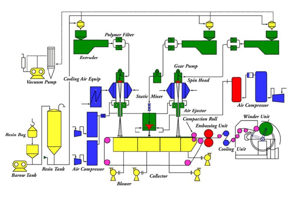
The major elements of the process are:
Polymer Feed. Polymer feedstock in pellet or powder form is conveyed from storage bins or silos to the feeder section of an extruder. Extruder. The extruder is one of the important elements in all polymer processing. It consists of a heated barrel with a rotating screw inside. Its main function is to melt the polymer pellets or granules and feed them to the next step/element. Extruder

56
The melting of the pellets in the extruder is due to the heat and friction of the viscous flow and the mechanical action between the screw and the walls of the barrel. There are four different heaters in the extruder, which are set in incremental order. The extruder is divided in to three different zones: Feed Zone: In the feed zone the polymer pellets are preheated and pushed to the next zone. ii) Transition Zone: The transition zone has a decreasing depth channel in order to compress and homogenize the melted polymer. iii) Metering Zone: This is the last zone in the extruder whose main purpose is to generate maximum pressure in order to pump the molten polymer in the forward direction. At this point the breaker plate controls the pressure generated with a screen pack placed near to the screw discharge. The breaker plate also filters out any impurities such as dirt, foreign particle metal particles and melted polymer lumps.
 Transition Zone: The transition zone has a decreasing depth channel in order to compress and homogenize the melted polymer. iii) Metering Zone: This is the last zone in the extruder whose main purpose is to generate maximum pressure in order to pump the molten polymer in the forward direction. At this point the breaker plate controls the pressure generated with a screen pack placed near to the screw discharge. The breaker plate also filters out any impurities such as dirt, foreign particle metal particles and melted polymer lumps.")
57
Gear pump The metering gear pump is a device for uniform melt delivery to the die assembly. It ensures consistent flow of clean polymer mix under process variations in viscosity, pressure, and temperature. The metering pump also provides polymer metering and the required process pressure. The metering pump typically has two intermeshing and counter-rotating toothed gears. The molten polymer from the gear pump goes to the feed distribution system to provide uniform flow to the die nosepiece in the die assembly.

58
Spinneret The molten polymer mix is pumped through a heated conduit to a resin filter system and then to a distributor section that leads to the spinnerette units.

59
The normal filters are often used for the fabrication of Polyester-Filaments and Micro-Filaments. The XL-Filters have an extremely large pore volume consisting of a large number of woven wire cloth layers with square aperture widths that are arranged over the specific filtration layer. The individual woven wire cloth layers are bonded together as one stable filtration layer via sintering. The edge is formed by a stainless sheet steel ring that, in combination with aluminium flat packings, creates a complete sealing. Depending on the individual usage, the filter layer consists of 15 up to 25 woven wire cloth layers. The pore sizes of the filtration layers range between 20 and 5 micrometers. The melt passes through the porous filtration layer, arrives at the spinneret nozzle with a high degree of homogeneity and is ideally suited for the spinning process. The spinnerette usually consists of a perforated plate arranged across the width of the line. The resin is forced through the many small holes in the spinnerette plate to form continuous filaments.

60
Quenching / Attenuation Zone
As the filaments emerge through the spinnerette holes, they are directed downward into quench chambers or chimneys. As the filaments travel through these chambers, cool air is directed across the filament bundle to cool the molten filaments sufficiently to cause solidification. The filaments are then led further downward into a tapered conduit by an airsteam. A second stream of high velocity air is directed parallel to the direction of the filaments, causing an acceleration and accompanying attenuation or stretching of the individual filaments. This mechanical stretching results in increased orientation of the polymer chains making up the continuous filament. Such orientation leads to increased filament strength, along with modification of other filament properties, including the filament denier or thickness.

61
Pneumatic jet for spunbonding
Web Forming The filaments are deposited in a random manner on a moving, porous forming belt. A vacuum under the belt assists in forming the filament web on the forming belt and in removing the air used in the extrusion / orientation operation. In some processes, an electrostatic charge is placed on the filament bundle to ensure spreading and separation of individual filaments. In other processes, deflector plates are used to lay down the filament sheet in a random manner on the forming belt.

62
In order for the web to achieve maximum uniformity and cover, individual filaments must be separated before reaching the belt. This is accomplished by inducing an electrostatic charge onto the bundle while under tension and before deposition. The charge may be induced triboelectrically or by applying a high voltage charge. The former is a result of rubbing the filaments against a grounded, conductive surface. Filaments are also separated by mechanical or aerodynamic forces. The method utilizes a rotating deflector plane to separate the filaments by depositing them in overlapping loops; suction holds the fiber mass in place. Bonding The continuous filament web is delivered to a bonding section, where one of several bonding methods can be used to bond the loose filaments into a strong, integrated fabric.

63
Process components Preparation of raw material Dosing unit for primary polymer, pigments and additives Extruder for melting and conveying the raw materials Melt filter Spin pump to ensure a constant throughput to the spin unit Sheet distributor with spinneret Filament cooling Filament extension Discharge unit (diffuser) Web forming machine for discharge and conveyance of the filaments Nonwoven bonding, preferable calendering Winding
 Web forming machine for discharge and conveyance of the filaments. Nonwoven bonding, preferable calendering. Winding.")
64
Process description: Out of the silo the polymer is vacuumfed to dosing station on top of the extruder. Inside the extruder it becomes melted and homogenised. Passing a filter system and a spin pump, the melt is distributed by a coathanger die, feeding the spinneret which forms a curtain of filaments. The filaments are cooled by means of a stream of air in a blowing area, drawn by aerodynamic forces and then transported to the downstream discharge channel. Here the filaments are swirled around and then deposited on the wire mesh belt as a random nonwoven material. This is transferred to the heat bonding calender which by heat and pressure sets the physical properties as tensiles and elongation of the final product. After calendering the material is cooled by a water-cooled pair of rolls and then wound up.

65
Physical properties High air permeability Thermo-bonded - no chemicals Excellent bi-directional and wear properties Soft and comfortable Grammage between g/m² (150 g/m²) if possible Possible additional nonwoven features: - Printing - Laminating - Electrostatic charging - improved hydrophilic properties through application of tensides By using additives or pigment pastes - Dying in every imaginable shade - fire-retardant properties - antistatic properties - increased UV and gamma ray protection Applications Hygiene Industrial applications Dust collectors Filtration
 if possible. Possible additional nonwoven features: - Printing - Laminating - Electrostatic charging - improved hydrophilic properties through application of tensides. By using additives or pigment pastes. - Dying in every imaginable shade - fire-retardant properties - antistatic properties - increased UV and gamma ray protection. Applications. Hygiene. Industrial applications. Dust collectors. Filtration.")
66
Spunbond line: 1 Dosing unit 2 Melt preparation 3 Filament production 4 Collection and conveyor unit 5 Nonwoven bonding 6 Nonwoven equipment 7 Winder

67
Production amount (thousand of tons)
Year 1989 1991 1993 1995 1997 1998 Total nonwovens production 414 480 554 646 759 836 Spun bond 143 197 227 268 318 356 under 25 g.m-2 tons g.m-2 tons g.m-2 tons over 150 g.m-2 tons

68
Protective Outer Layers - A bi-component spunbond, using sheath-core technology. The inner core is polypropylene for strength, with a polyethylene wrap for softness. A silver-gray color was selected because of its heat-resistant properties. The fabric is also treated with UV inhibitors for extended outdoor use. Micro-Porous Middle Layer - The barrier layer is breathable film, a proprietary stretch-film technology developed exclusively for Kimberly-Clark. The film is stretched and subjected to a chemical process that creates microscopic holes smaller than droplets of water or dust, yet large enough to allow moisture vapor to escape. Soft, Paint-Protecting Inner Layer - A bi-component fabric made with polyethylene and nylon. This combination results in an exceptionally high strength-to-weight ratio, with the "soft touch" necessary for today's water-based paint finishes. SB 16 segment pie -70PET_30PA66 SB side-by-side -60PET_40PA66

69
In-line-production is illustrated schematically in figure 4
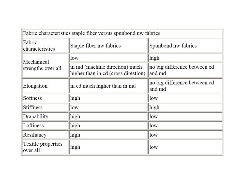
In-line-production is illustrated schematically in figure 4.10, starting from polymer granule and ending with the ultrafine microfiber spunbond fabric. Two different polymers are transported by extruders to the spinneret, leaving it as bicomponental endless filaments, which are quenched and stretched by air streams with a very high speed up to sonic velocity. The stretched filaments are finally laid down onto a moving belt to form a nonwoven fabric of uniform structure. As demonstrated later in more detail the fiber distribution is more or less an isotropical one. Mechanical strengths are practically the same in machine and cross direction which might beneficial for most part of applications.

70
Summerized over all conventional spunbond nonwoven fabrics provide much higher mechanical strengths in md and cd than carded nonwoven fabrics but because of the non crimped fibers all characteristics derived from such as softness, drapability, loftiness and the like are uncomparably worse than with carded nonwoven fabrics. Expressed somewhat simplified: the non-textile characteristics of conventional spunbonds has been so unfavorable that huge areas of application such as garment industry or upper material for shoes and luggage could not be covered by them.

72
Melt blown Melt blowing is a process for producing fibrous webs directly from polymers using high-velocity air to attenuate the filaments. MB microfibers generally have diameters in the range of 2 to 4 μm, although they may be as small as 0.1 μm and as large as 10 to 15 μm. Differences between MB nonwoven fabrics and other nonwoven fabrics, such as degree of softness, cover or opacity, and porosity can generally be traced to differences in filament size. The Melt blowing is process in which high-velocity air blows a molten thermoplastic resin from an extruder die tip onto a conveyor or takeup screen to form a fine fiberous and self-bonding web.

73
The die assembly is the most important element of the melt blown process. It has three distinct components: polymer-feed distribution, die nosepiece, and air manifolds. Essential features of the process: Resin storage and resin preparation Metering unit for main polymer, pigments and additives Extruder for plastification of the polymeric components Melt filter Melt pipe to spin pump Spin pump to maintain a constant throughput to the spinneret MeltBlown die head Hot air supply Conveyor belt machine, height adjustable Winding system Approx. 40% of the MeltBlown material is manufactured in a stand-alone process. The remaining meltblown materials are combined with spunbonded fabrics or laminates to form other materials. Combinations with spunbonded fabrics are primarily used to make nonwoven materials with barrier properties. Another variation is the combination of MeltBlown with cellulose or an absorbent powder, to produce a soft, strong but still absorbent material, which can retain absorbed liquid whilst still keeping its strength.

74
Polymer The MeltBlown process allows the use of various different polymers: polypropylene MFI , polyethylene MFI , polyester iV 0,53 - 0,64, polyamide, polyurethane, polyphenylene sulphide. All of the polymers used during MeltBlown production must have a low viscosity. This results in a relatively high melt temperature (compared to other production processes). The melt temperature can be adjusted during production by means of electrical heating systems in the extrusion section. Components Preparation of raw material Dosage unit for primary polymer, pigment pastes and additives Extruder for melting and conveying the raw materials Melt filter Spin pump to ensure a constant throughput to the spin unit Meltblown die to form the filaments Hot air supply Web forming machine for depositing the filaments, height adjustable Winder

75
Physical properties Self-bonding / thermo-bonded Large area-to-weight ratio Adjustable pores and capillary structure PP MeltBlown nonwoven material is hydrophobic / oleophilic Excellent wick properties / liquid retention High filtration efficiency Thermal insulation Elasticity Preferred grammage spectrum g/m² Preferred filament diameter 1 -2 μm Porosity Surface energies Colours can be used .. and many others

76
Melt blown die - The feed distribution in a melt-blown die is more critical than in a film or sheeting die for two reasons. First, the melt-blown die usually has no mechanical adjustments to compensate for variations in polymer flow across the die width. Second, the process is often operated in a temperature range where thermal breakdown of polymers proceeds rapidly. The feed distribution is usually designed in such a way that the polymer distribution is less dependent on the shear properties of the polymer. This feature allows the melt blowing of widely different polymeric materials with one distribution system. The feed distribution balances both the flow and the residence time across the width of the die.

77
Two types of die nosepiece: capillary and drilled hole
Two types of die nosepiece: capillary and drilled hole. From the feed distribution channel the polymer melt goes directly to the die nosepiece. The die nosepiece is a wide, hollow, and tapered piece of metal having several hundred orifices or holes across the width. The polymer melt is extruded from these holes to form filament strands which are subsequently attenuated by hot air to form fine fibers. A typical die nosepiece has approximately 0.4-mm diameter orifices spaced at 1 to 4 per millimeters (25 to 100 per inch). For the capillary type, the individual orifices are actually slots that are milled into a flat surface and then matched with identical slots milled into a mating surface. The two halves are then matched and carefully aligned to form a row of openings or holes. By using the capillary type, the problems associated with precise drilling of very small holes are avoided. In addition, the capillary tubes can be precisely aligned so that the holes follow a straight line accurately. The drilled-hole type has very small holes drilled by mechanical drilling or electric discharge matching (EDM) in a single block of metal.
. For the capillary type, the individual orifices are actually slots that are milled into a flat surface and then matched with identical slots milled into a mating surface. The two halves are then matched and carefully aligned to form a row of openings or holes. By using the capillary type, the problems associated with precise drilling of very small holes are avoided. In addition, the capillary tubes can be precisely aligned so that the holes follow a straight line accurately. The drilled-hole type has very small holes drilled by mechanical drilling or electric discharge matching (EDM) in a single block of metal.")
78
Air manifolds The air manifolds supply the high velocity hot air through the slots on the top and bottom sides of the die nosepiece. The high velocity air is generated using an air compressor. The compressed air is passed through a heat exchange unit such as an electrical or gas heated furnace, to heat the air to desired processing temperatures. Typical air temperatures range from 230°C to 360°C at velocities of 0.5 to 0.8 the speed of sound. As soon as the molten polymer is extruded from the die holes, high velocity hot air streams attenuate the polymer streams to form microfibers. As the hot air stream containing the microfibers progresses toward the collector screen, it draws in a large amount of surrounding air that cools and solidifies the fibers. The solidified fibers subsequently get laid randomly onto the collecting screen, forming a self-bonded nonwoven web. The fibers are generally laid randomly because of the turbulence in the air stream, but there is a small bias in the machine direction due to some directionality imparted by the moving collector. The collector speed and the collector distance from the die nosepiece can be varied to produce a variety of melt-blown webs. Usually, a vacuum is applied to the inside of the collector screen to withdraw the hot air and enhance the fiber laying process.

79
Machine variables Machine variables, also called operational variables, are related to the machine and can be changed while the equipment is being operated. These variables include air temperature, polymer/die temperature, die to collector distance, collector speed, polymer throughput and air throughput. All of these affect the final properties of the nonwoven web. i) Polymer Throughput and Air Flow: both polymer throughput and air flow rate control the final fiber diameter, fiber entanglement, basis weight and the attenuating zone. ii) Polymer/Die and Air Temperature: These variables combined with air flow rate affect the uniformity, shot formation (large globules of nonfibrous polymer larger in diameter than fibers in webs), rope and fly formation, fabric appearance and feel (soft or stiff). iii) Die to Collector Distance: This affects the openness of the fabric, thermal bonding among the fibers and basis weight. Off-line variables Off-line variables are fixed during a process run and can only be changed when the machine is not in operation. These variables are air gap, air angle, die setback, and die hole size. i) Die Hole Size: Die hole size along with die set back affects the fiber size. ii) Air Gap: It affects the degree of fiber breakage by controlling the air exit pressure. iii) Air Angle: It controls the nature of air flow, i.e. as the air angle approaches 90° it results in a high degree of fiber separation or turbulence that leads to random fiber distribution. At an angle of 30°, roped or parallel fibers deposited as loosely coiled bundles of fibers are generated. This structure is undesirable. At angles greater than 30°, attenuation as well as breakage of fibers occurs.
 Polymer Throughput and Air Flow: both polymer throughput and air flow rate control the final fiber diameter, fiber entanglement, basis weight and the attenuating zone. ii) Polymer/Die and Air Temperature: These variables combined with air flow rate affect the uniformity, shot formation (large globules of nonfibrous polymer larger in diameter than fibers in webs), rope and fly formation, fabric appearance and feel (soft or stiff). iii) Die to Collector Distance: This affects the openness of the fabric, thermal bonding among the fibers and basis weight. Off-line variables. Off-line variables are fixed during a process run and can only be changed when the machine is not in operation. These variables are air gap, air angle, die setback, and die hole size. i) Die Hole Size: Die hole size along with die set back affects the fiber size. ii) Air Gap: It affects the degree of fiber breakage by controlling the air exit pressure. iii) Air Angle: It controls the nature of air flow, i.e. as the air angle approaches 90° it results in a high degree of fiber separation or turbulence that leads to random fiber distribution. At an angle of 30°, roped or parallel fibers deposited as loosely coiled bundles of fibers are generated. This structure is undesirable. At angles greater than 30°, attenuation as well as breakage of fibers occurs.")
80
Stand-alone type The characteristic feature of the stand-alone system is the collector, which can be adjusted in height and angle. This patented design allows precise control of the MeltBlown deposition.

81
Inline type Since the common collectors of composite-lines have static height, the adjustment of the die-distance to collector belt (DCD) is done by vertical movement of the entire operating platform.
 is done by vertical movement of the entire operating platform.")
82
Properties of melt-blown
Melt-blown webs usually have a wide range of product characteristics. The main characteristics and properties of melt-blown webs are as follows: − Random fiber orientation. − Lower to moderate web strength, deriving strength from mechanical entanglement and frictional forces. − Generally high opacity (having a high cover factor). − Fiber diameter ranges from 0.5 to 30 μm, but typically from 2-7 μm. − Basis weight ranges from g/m2, but typically g/m2. − Microfibers provide a high surface area for good insulation and filtration characteristics. − Fibers have a smooth surface texture and are circular in cross-section. − Most melt-blown webs are layered or shingled in structure, the number of layers increases with basis weight. The fiber length in a melt-blown web is variable; it can be produced in the range from a few millimeters to several hundred centimeters in length and usually exists over a broad range. The fiber cross-section is also variable, ranging from circular to a flat configuration and other variations.
. − Fiber diameter ranges from 0.5 to 30 μm, but typically from 2-7 μm. − Basis weight ranges from g/m2, but typically g/m2. − Microfibers provide a high surface area for good insulation and filtration characteristics. − Fibers have a smooth surface texture and are circular in cross-section. − Most melt-blown webs are layered or shingled in structure, the number of layers increases with basis weight. The fiber length in a melt-blown web is variable; it can be produced in the range from a few millimeters to several hundred centimeters in length and usually exists over a broad range. The fiber cross-section is also variable, ranging from circular to a flat configuration and other variations.")
83
Type of polymer The type of polymer or resin used will define the elasticity, softness, wetability, dyeability, chemical resistance and other related properties of formed fibers. One of the advantages of melt-blown technology is to handle many different polymers as well as mixture of polymers. Some polymers, which can be melt-blown, are listed below. However, the list is not complete. − Polypropylene is easy to process and makes good web. − Polyethylene is more difficult to melt-blow into fine fibrous webs than is polypropylene. Polyethylene is difficult to draw because of its melt elasticity. − PBT (poly-butylene terephalate) processes easily and produces very soft, fine-fibered webs. − Nylon 6 is easy to process and makes good webs. − Nylon 11 melt-blows well into webs that have very unusual feel like leather. − Polycarbonate produces very soft-fiber webs. − Poly (4-methyl pentene-1) blows well and produces very fluffy soft webs. − Polystyrene produces an extremely soft, fluffy material with essentially no shot defects. The most widely used polymer that has a high MFR is polypropylene. Polypropylene with its low viscosity has a low melting point and is easy to draw into fibers. It comprises 70-80% of the total North American production. The feasibility of MB original and recycled PET has also been studied. PET webs have a strong tendency to shrink, depending on the airflow rate used. PET webs produced at high airflow rate shrink more than those produced at low airflow rate because of their higher level of molecular orientation. Heat-setting of melt-blown PET webs or, alternatively, the use of PBT was suggested as a possible means of producing thermally stable melt-blown PET nonwovens.
 processes easily and produces very soft, fine-fibered webs. − Nylon 6 is easy to process and makes good webs. − Nylon 11 melt-blows well into webs that have very unusual feel like leather. − Polycarbonate produces very soft-fiber webs. − Poly (4-methyl pentene-1) blows well and produces very fluffy soft webs. − Polystyrene produces an extremely soft, fluffy material with essentially no shot defects. The most widely used polymer that has a high MFR is polypropylene. Polypropylene with its low viscosity has a low melting point and is easy to draw into fibers. It comprises 70-80% of the total North American production. The feasibility of MB original and recycled PET has also been studied. PET webs have a strong tendency to shrink, depending on the airflow rate used. PET webs produced at high airflow rate shrink more than those produced at low airflow rate because of their higher level of molecular orientation. Heat-setting of melt-blown PET webs or, alternatively, the use of PBT was suggested as a possible means of producing thermally stable melt-blown PET nonwovens.")
84
Melt blown - bicomponent fibers
Bicomponent melt blown systems produce sheath/core, side-by-side, tipped trilobal and tipped cross fibers with approximately 2 micron diameters. These bicomponent systems operate on conventional meltblown spin hole densities. In addition, Hills has developed melt blown dies with 100 holes per inch that operate with homopolymer at throughputs up to 0.5 grams per hole per minute. In combination with the patented Hills-meltdistribution Reifenhäuser REICOFIL delivers Bico-Nonwovenlines up to 4.2m working width.

85
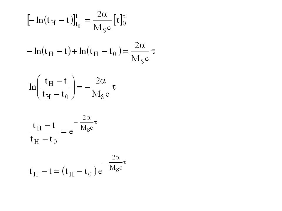
Poznámka k energetické náročnosti technologie:
Výroba vlákenných vrstev z velmi jemných vláken vyžaduje energii k tavení polymeru a pohonům pohyblivých součástí stroje stejně jako spunbond, navíc se však spotřebuje značné množství energie k přípravě a ohřevu velkého množství vzduchu. Tuto energii nelze získávat zpět. Energie se, fyzikálně vzato spotřebuje na tvorbu velkého měrného povrchu materiálu, resp. povrchové energie na tento povrch vázané. Měrný povrch vláken roste s jejich klesajícím průměrem. Úvahu o souvislosti spotřeby energie s průměrem vytvořených vláken lze založit na rovnosti průtoků hmoty polymeru ve zvlákňovací trysce hubice a hmoty vlákna konečného průměru a rychlosti:

86
The polymer flow where ϕ is density of polymer d0 is diameter of spinning nozzle v0 polymer flow rate into the nozzle d final diameter of fiber vf final (maximal) fiber rate
 fiber rate.")
87
Za zjednodušeného předpokladu, že maximální dosažená rychlost vlákna vje úměrná rychlosti vzduchu a tedy množství vzduchu proteklého za jednotku času, t. j. i energii potřebné k transportu vzduchu a jeho ohřevu, lze odhadnout energii potřebnou k formování hmotnostní jednotky vlákna daného průměru z v. Výše uvedenou rovnici upravíme na Vztah ukazuje, že vynaložená energie při konstantním dávkování polymeru dm/dt klesá s rostoucím čtvercem průměru vlákna. Stejným způsobem tedy roste se zmenšujícím se průměrem vlákna (zmenšení průměru vlákna x-krát vyžaduje x-krát více energie). Spotřeba energie při výrobě běžných typů vláken (o průměrech 1 – 4 mikrometry) technologií melt blown z různých typů polymerů se pohybuje v mezích 2,7 – 9 kWh na 1 kg výrobku.
. Spotřeba energie při výrobě běžných typů vláken (o průměrech 1 – 4 mikrometry) technologií melt blown z různých typů polymerů se pohybuje v mezích 2,7 – 9 kWh na 1 kg výrobku.")
88
Flash spinning PE/spin agent solution
Solvent is evaporated - bubbles split polymer to the fibrils Flash-spinning is a deviation from the conventional melt spinning process and is a process created by DuPont company. In flash-spinning, pure solvent droplets and highly saturated polymer/solvent mixtures are decompressed through a spin orifice. As the pressurized solution is allowed to expand rapidly through the orifice, the solvent is instantaneously "flashed off," leaving behind a three-dimensional film-fibril network.

89
The micro-denier fibers that are produced via this process are interconnected in a continuous network and collected on a moving belt. Then, the sheet is subjected to either full-surface thermal bonding, which creates a stiff, paper-like sheet, or point bonding, followed by in-line softening which creates a drapeable, fabric-like sheet. No binders are used. As a result of this unique process—and its composition of 100% high-density polyethylene—the finished product offers a high surface area and enhanced filtration efficiency, as well as good sheet tensile and high tear strength.

90
Applications Construction One of the most popular and widely known applications of Tyvek® is in the construction industry, where it is used to increase air and water resistance, helping to lower heating and cooling costs in buildings and providing better protection against water and moisture intrusion. The unique qualities of Tyvek® help stop air flow through wall cavities; help hold out bulk water and wind-driven rain; and allow moisture vapor to escape from inside walls. The result is a more comfortable, energy-efficient building with far fewer chances for damage from degradation effects. Medical Packaging Tyvek® is used in virtually every form of sterile medical packaging. That's because Tyvek® delivers an optimum balance of bacteria penetration resistance, tear strength, puncture resistance and clean peel, as well as compatibility with existing and emerging sterilization methods. Protective Apparel Garments made of Tyvek® are either used for hazardous environments or for general, non-hazardous, industrial use. Examples of uses for hazardous environments include protection against water-based acids, bases, salts and splashes of certain liquids, such as pesticides and herbicides.

91
Envelopes The unique composition of Tyvek® results in virtually the strongest envelope available – offering superior protection from punctures, tears and moisture. Remarkably light, Tyvek® envelopes can help to save on mailing costs. Graphics Among the first graphic products manufactured from hard-structure Tyvek® were outdoor advertising posters and banners; labels; tags; and schoolbook covers – applications that benefit from its water, abrasion and tear resistance. Today, many more graphics uses have been found for Tyvek®, such as highly durable maps and guidebooks; chemical container labels; workshop manuals; race numbers for marathon runners; and frozen food labels. Covers Because Tyvek® is water resistant, yet breathable, it is ideal for car, boat and camper covers. The unique nonwoven structure of Tyvek® protects against acid rain and salt spray by holding out more water than cotton, polyester or cotton/polyester covers; however, because it is breathable, it also allows trapped moisture to escape, helping to prevent rot and mildew.

92
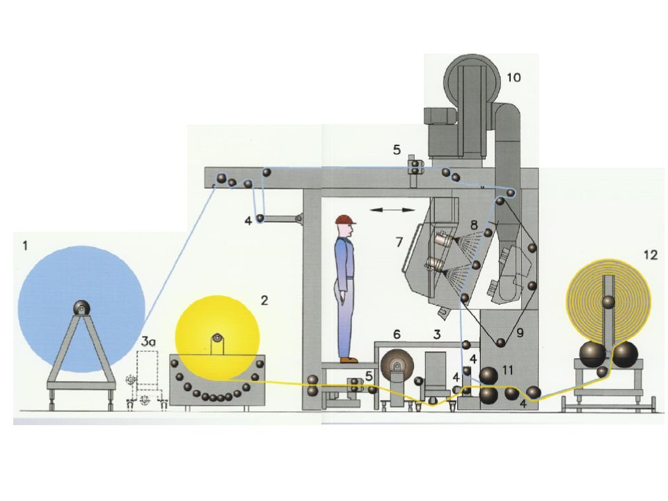
Spunbond and melt blown modification
SMS

93
SMS The operation begins by spinning continuous filaments from the spunbond die of station one. The filaments pass through the quenching zone, which cools and prevents them from sticking together. The quenched filaments pass through a stretching zone where discharged air further draws down and attenuates the filaments. Filaments are randomly deposited on the conveyor. Air passes through the conveyor and is withdrawn by the vacuum system. The first layer is conveyed under the spinning assembly in station two where micro-sized fibers are blown on top of the first layer, forming a meltblown layer on the spunbond. Average fiber diameter ranges from 0.5 to 15 microns. A fiber diameter of 1 to 10 microns is considered good, while 2 to 6 microns is excellent. The two-layer laminate is conveyed under station three where a layer of spunbond filaments is deposited on the meltblown layer, completing the SMS structure. The threelayer composite may then pass though a calender or other device to bond the layers together in the conventional manner. draw

95
Typical products of spunbond and meltblown technologies
Product Fabric Disposable Diaper, Incontinence Largest single market segment in nonwovens for cloth-like backsheet, leg cuff and cover stock Durable Papers Almost exclusively Tyvek® polyethylene spunbond fabric (Tyvek is a registered trademark of E.I. DuPont de Nemours & Co.) Disposable, Protective Apparel Dominated by Tyvek polyethylene spunbond fabric, although growing use of polypropylene spunbond and composite materials Bedding, Pillows, Furnishings Competitive market segment using polypropylene and polyester spunbonds Geotextiles Heavyweight polypropylene and polyester spunbonds, and needlepunch polypropylene and woven fabrics
 Disposable, Protective Apparel Dominated by Tyvek polyethylene spunbond fabric, although growing use of polypropylene spunbond and composite materials. Bedding, Pillows, Furnishings Competitive market segment using polypropylene and polyester spunbonds. Geotextiles Heavyweight polypropylene and polyester spunbonds, and needlepunch polypropylene and woven fabrics.")
96
Typical products of spunbond and meltblown technologies
Product Fabric Furniture Polypropylene spunbond fabric, polypropylene needlepunch and polyester spunbond fabric Filtration Spunbond and meltblown fabric for liquid and air filtration Automotive, Carpet, Trim Heavyweight polyester spunbond fabrics Carpet Underlayment Carpet backings consisting of PET, polyamide and polypropylene spunbond fabrics Medical Products Spunbond and spunbond/meltblown composite fabrics Roofing Typically polyester spunbonds

97
Airlaid sorbents are manufactured from the 100% polypropylene fibers
Airlaid sorbents are manufactured from the 100% polypropylene fibers. The polypropylene fibers are ultrasonically bonded between two layers of spunbond fabric. Sonic bonded low-lint absorbents are manufactured by ultrasonically bonding two layers of melt-blown polypropylene. This construction gives sonic bonded products greater strength than regular melt-blown sorbents, and also provides low-lint properties. Fine fiber sorbents consist of two layers of fine fiber polypropylene ultrasonically bonded around a high-loft melt-blown core. These low-lint pads and rolls have the highest absorption rates of all our products.

98
Oil control products FineFiber technology produces densely-woven, small-diameter strands of fiber to increase surface area for fast absorption and firmer grip. Add 3-ply construction for extra durability and you have a mat that you can walk on safely and is virtually indestructible to foot traffic. AirLaid technology produces a resilient bounce-back polypropylene fiber that creates uniform pockets of air space that sorb and hold liquids. Insert AirLaid polypropylene between two layers of tough spunbond and bond ultrasonically for added strength. Now you have an ideal mat for wrapping around pipes or fitting into tight spots to help maintain a cleaner, safer workplace.

99
MultiLaminate technology produces a super-strong, heavy-weight mat for rugged applications. Outer spunbond layers constructed of continuous strands of interwoven polypropylene fibers provide toughness while the MeltBlown inner layer draws and traps ugly grime inside. Resistant to tears and abrasions, this mat is perfect for lining tool cribs and placing under jagged parts and heavy equipment. SonicBonded technology produces a high-loft mat for faster, greater absorbency. Fuse the layers together with ultrasonic weld points and you’ve got a mat that sucks up to 57.5 gallons per roll and keeps its shape even when fully saturated. In other words, it won’t fall apart! Great for overspray areas and indoor spills where clean, dry floors are important for safety.

100
Primary process characteristics:
Modular structure of the spunbonding and melt blown components Common operating console for all spinning stations Common high-speed spinning belt for all spinning stations. High-speed winding system with downstream slitter/rewinder Applications Barrier products Diaper edges Filtration Covers for superabsorbents Medical applications (for example surgery covers) Physical properties Thermo-bonded High resistance against water column Thermal insulator Preferred grammage range g/m² Dyable
 Physical properties. Thermo-bonded. High resistance against water column. Thermal insulator. Preferred grammage range g/m². Dyable.")
101
Electrostatic spinning
In the electrospinning process a high voltage is used to create an electrically charged jet of polymer solution or melt, which dries or solidifies to leave a polymer fiber. One electrode is placed into the spinning solution/melt and the other attached to a collector. Electric field is subjected to the end of a capillary tube that contains the polymer fluid held by its surface tension. This induces a charge on the surface of the liquid. Mutual charge repulsion causes a force directly opposite to the surface tension. As the intensity of the electric field is increased, the hemispherical surface of the fluid at the tip of the capillary tube elongates to form a conical shape known as the Taylor cone. With increasing field, a critical value is attained when the repulsive electrostatic force overcomes the surface tension and a charged jet of fluid is ejected from the tip of the Taylor cone. The discharged polymer solution jet undergoes a whipping process wherein the solvent evaporates, leaving behind a charged polymer fiber, which lays itself randomly on a grounded collecting metal screen. In the case of the melt the discharged jet solidifies when it travels in the air and is collected on the grounded metal screen.

102
Electrostatic spinning - This technology consists depositing the polymer onto a conveyer of heated wires giving a high voltage potential. The polymer covering the wires, pass over the second conveyer with substrate onto witch the fibers are created.

103
Parameters: − Molecular Weight, Molecular-Weight Distribution and Architecture (branched, linear etc.) of the polymer − Solution properties (viscosity, conductivity & and surface tension − Electric potential, Flow rate & Concentration − Distance between the capillary and collection screen − Ambient parameters (temperature, humidity and air velocity in the chamber) − Motion of target screen An important characteristic of electrospinning is the ability to make fibers with diameters in the range of manometers to a few microns. Consequently these fibers have a large surface area per unit mass so that nanowoven fabrics of these nanofibers collected on a screen can be used for example, for filtration of submicron particles in separation industries and biomedical applications, such as wound dressing in medical industry, tissue engineering scaffolds and artificial blood vessels. The use of electrospun fibers at critical places in advanced composites to improve crack resistance is also promising.
 − Motion of target screen. An important characteristic of electrospinning is the ability to make fibers with diameters in the range of manometers to a few microns. Consequently these fibers have a large surface area per unit mass so that nanowoven fabrics of these nanofibers collected on a screen can be used for example, for filtration of submicron particles in separation industries and biomedical applications, such as wound dressing in medical industry, tissue engineering scaffolds and artificial blood vessels. The use of electrospun fibers at critical places in advanced composites to improve crack resistance is also promising.")
104
Electrostatic spinning - a schematic diagram of electrospinning

105
The process makes use of electrostatic and mechanical force to spin fibers from the tip of a fine orifice or spinneret. The spinneret is maintained at positive or negative charge by a DC power supply. When the electrostatic repelling force overcomes the surface tension force of the polymer solution, the liquid spills out of the spinneret and forms an extremely fine continuous filament. It has the misleading appearance of forming multiple filaments from one spinneret nozzle, but current theory is that the filaments do not split. These filaments are collected onto a rotating or stationary collector with an electrode beneath of the opposite charge to that of the spinneret where they accumulate and bond together to form nanofiber fabric. The distance between the spinneret nozzle and the collector generally varies from 15 –30 cm. The process can be carried out at room temperature unless heat is required to keep the polymer in liquid state. The final fiber properties depend on polymer type and operating conditions. Fiber fineness can be generally regulated from ten to a thousand nanometers in diameter.

106
Solution spinning 1 – polymer solution, 2 – rotating charged electrode, 3 - counter electrode, 4 – container, 5 - supporting material, 6 - unreeling device, 7 - reeling device, 8 - formation of the nanofibers, 9 - vacuum chamber

107
A device for nanofibres production from a polymer solution uses electrostatic spinning in an electric field created by a potential difference between a charged electrode and a counter electrode consisting of a container (4) at least partly filled with a polymer solution (1) in which is by a part of its circumference immersed pivoted cylinder (2), which is by a well-known not represented method connected to a source of DC voltage and which forms a charged electrode. Against a free part of the circumference of the charged electrode (2) is a counter electrode (3) with a different potential situated, which is usually connected to earth (grounded), as described in Fig. 4.21, or it is by a well-known not represented method connected to a source of DC voltage of a different polarity. By rotating the charged electrode, where its part of its circumference is immersed in the polymer solution, is the polymer solution drawn by the circumference of the charged electrode from the container into the space between the charged electrode and the counter electrode, where an electric field is formed. Here on the surface of the charged electrode are from the polymer solution formed Taylor cones of a high stability and they present places of primary formation of the nanofibres (8). The formed nonofibres are by the effects of electric field drift away to the counter electrode and consequently they are deposited on the surface of the backing fabric presenting plane supporting material (5) of the nanofibres into a layer, which thickness is controlled using the velocity of the unreeling device (6) and the reeling device (7). The drift of the nanofibres away of the charged electrode to the counter electrode is promoted by streaming of air sucked from the outer space into the vacuum chamber (9) and passing along the polymer solution container and the charged electrode and passing through the backing fabric presenting plane supporting material of the nanofibres and the counter electrode. A method and a device according to the invention are applicable for production of layers of nanofibres in diameters from 50 to 200 nanometers. These layers can be used for filtration, as battery separators, for production of special composites, for construction of sensors with extremely low time constant, for production of protective clothes, in medicine and other fields.
 with a different potential situated, which is usually connected to earth (grounded), as described in Fig. 4.21, or it is by a well-known not represented method connected to a source of DC voltage of a different polarity. By rotating the charged electrode, where its part of its circumference is immersed in the polymer solution, is the polymer solution drawn by the circumference of the charged electrode from the container into the space between the charged electrode and the counter electrode, where an electric field is formed. Here on the surface of the charged electrode are from the polymer solution formed Taylor cones of a high stability and they present places of primary formation of the nanofibres (8). The formed nonofibres are by the effects of electric field drift away to the counter electrode and consequently they are deposited on the surface of the backing fabric presenting plane supporting material (5) of the nanofibres into a layer, which thickness is controlled using the velocity of the unreeling device (6) and the reeling device (7). The drift of the nanofibres away of the charged electrode to the counter electrode is promoted by streaming of air sucked from the outer space into the vacuum chamber (9) and passing along the polymer solution container and the charged electrode and passing through the backing fabric presenting plane supporting material of the nanofibres and the counter electrode. A method and a device according to the invention are applicable for production of layers of nanofibres in diameters from 50 to 200 nanometers. These layers can be used for filtration, as battery separators, for production of special composites, for construction of sensors with extremely low time constant, for production of protective clothes, in medicine and other fields.")
108
Polymer solvent systems used in electrospinning -
Nylon 6 and nylon 66 Formic Acid Polyacrylonitrile Dimethyl formaldehyde PET Trifluoroacetic acid/Dimethyl chloride PVA Water Polystyrene DMF/Toluene Nylon-6-co-polyamide Formic acid Polybenzimidazole Dimethyl acetamide Polyramide Sulfuric acid Polyimides Phenol

109
THERMAL BONDING METHODS – thermal flow
where D is diffusion coefficient and concentration gradient. Diffusion Thermal energy flow where is thermal energy flow, thermal conductivity and thermal gradient. Temperature distribution T in the time and in the space where is time and x distance from the heat transfer surface

110
Proces, při kterém v koncentračně nehomogenním systému dochází k samovolnému vyrovnávání koncentrací, se nazývá difuze. Příčinou toku látky jsou rozdíly v její koncentraci. Hnací silou je koncentrační gradient, tj. změna koncentrace složky se vzdáleností, (dc/dx [mol/m3]). Změna látkového množství dn za čas dτ při průchodu plochou A je dle 1.Fickova zákona při jednorozměrné difuzi dána vztahem (stacionární difuze - v libovolném bodě se koncentrace nemění s časem.) kde D je difuzní koeficient látky v prostředí. Difuzní koeficient udává počet molů dané složky, která projde jednotkovou plochou za jednotku času při jednotkovém spádu koncentrace složky. Hlavní jednotka: m2s-1. Rozložení koncentrace v závislosti na souřadnici a čase je dán 2. Fickovým zákonem (nestacionární difuze - koncentrační gradient se s časem mění, difuzní tok se mění s polohou,)
. Změna látkového množství dn za čas dτ při průchodu plochou A je dle 1.Fickova zákona při jednorozměrné difuzi dána vztahem (stacionární difuze - v libovolném bodě se koncentrace nemění s časem.) kde D je difuzní koeficient látky v prostředí. Difuzní koeficient udává počet molů dané složky, která projde jednotkovou plochou za jednotku času při jednotkovém spádu koncentrace složky. Hlavní jednotka: m2s-1. Rozložení koncentrace v závislosti na souřadnici a čase je dán 2. Fickovým zákonem (nestacionární difuze - koncentrační gradient se s časem mění, difuzní tok se mění s polohou,)")
111
Tok tepelné energie Řídí se Fourierovým zákonem kde jel je tok tepelné energie, l tepelná vodivost [W.m-1.K-1 ]a teplotní spád. Rozložení teploty T [K] v čase a prostoru je pak dáno vztahem kde t je čas a x vzdálenost od teplosměnné plochy. Odvození výše uvedeného vztahu je obdobné odvození 2. Fickova zákona o difusi, kde a [m2s-1] je tzv. teplotní vodivost Kde c je měrná tepelná kapacita prostředí [Jkg − 1K − 1 ] a r je měrná hmotnost [kg.m-3]
![Tok tepelné energie Řídí se Fourierovým zákonem. kde jel je tok tepelné energie, l tepelná vodivost [W.m-1.K-1 ]a teplotní spád.](http://slideplayer.com/slide/10161289/34/images/111/Tok+tepeln%C3%A9+energie+%C5%98%C3%ADd%C3%AD+se+Fourierov%C3%BDm+z%C3%A1konem.+kde+jel+je+tok+tepeln%C3%A9+energie%2C+l+tepeln%C3%A1+vodivost+%5BW.m-1.K-1+%5Da+teplotn%C3%AD+sp%C3%A1d..jpg "Rozložení teploty T [K] v čase a prostoru je pak dáno vztahem. kde t je čas a x vzdálenost od teplosměnné plochy. Odvození výše uvedeného vztahu je obdobné odvození 2. Fickova zákona o difusi, kde a [m2s-1] je tzv. teplotní vodivost. Kde c je měrná tepelná kapacita prostředí [Jkg − 1K − 1 ] a r je měrná hmotnost [kg.m-3]")
112
Heating of 2D layers Let ‘s have a fiber layer of area S, surface density of Ms ant thickness of h. The total mass of this textile is Temperature difference between the two surfaces of textile

113
Ohřev vlákenných vrstev
Při výpočtu je brána v úvahu hmotnost vrstev a odpovídající měrné teplo. Dvourozměrnost vrstev je zde chápána v tom smyslu, že se nestuduje časově závislé rozložení teploty vrstvy v její tloušťce, ale teplota vrstvy je chápána jako průměrná přes momentální teplotní profil v tloušťce vrstvy. Mějme plošnou vlákennou vrstvu o ploše S, plošné hmotnosti MS a tloušťce h. celková hmotnost této textilie je Budiž teplota vrstvy t-to v čase t-to. Přivedeme-li oba povrchy vrstvy v čase t-to do kontaktu s ohřevnými tělesy o stálé teplotě tH>to, bude teplo přecházet z těchto ohřevných těles do vrstvy. Předpokládáme přitom, že ohřevná tělesa jsou vybavena dostatečně výkonným topením, které zabezpečí jejich stálou teplotu v čase, takže se neochlazují vlivem kontaktu s chladnější vrstvou.

114
Množství tepla vstupujícího do vrstvy za jednotku času bude úměrné ploše styku vrstvy s ohřevným tělesem (2S) a momentálnímu teplotnímu rozdílu tH-t. Konstantu úměrnosti mezi a tH-t nazýváme součinitelem přestupu tepla a [Wm-2K-1]. a závisí na charakteru povrchů obou těles, která jsou ve styku a lze ji stanovit experimentálně. Vstupující teplo Q [J] způsobuje vzrůst teploty vrstvy. Vzrůst teploty závisí na hmotnosti vrstvy M a jejím měrném teple c: Tuto diferenciální rovnici řešíme separací proměnných, kde MS je plošná hmotnost vrstvy
![Množství tepla vstupujícího do vrstvy za jednotku času bude úměrné ploše styku vrstvy s ohřevným tělesem (2S) a momentálnímu teplotnímu rozdílu tH-t. Konstantu úměrnosti mezi a tH-t nazýváme součinitelem přestupu tepla a [Wm-2K-1]. a závisí na charakteru povrchů obou těles, která jsou ve styku a lze ji stanovit experimentálně.](http://slideplayer.com/slide/10161289/34/images/114/Mno%C5%BEstv%C3%AD+tepla+vstupuj%C3%ADc%C3%ADho+do+vrstvy+za+jednotku+%C4%8Dasu+bude+%C3%BAm%C4%9Brn%C3%A9+plo%C5%A1e+styku+vrstvy+s+oh%C5%99evn%C3%BDm+t%C4%9Blesem+%282S%29+a+moment%C3%A1ln%C3%ADmu+teplotn%C3%ADmu+rozd%C3%ADlu+tH-t.+Konstantu+%C3%BAm%C4%9Brnosti+mezi+a+tH-t+naz%C3%BDv%C3%A1me+sou%C4%8Dinitelem+p%C5%99estupu+tepla+a+%5BWm-2K-1%5D.+a+z%C3%A1vis%C3%AD+na+charakteru+povrch%C5%AF+obou+t%C4%9Bles%2C+kter%C3%A1+jsou+ve+styku+a+lze+ji+stanovit+experiment%C3%A1ln%C4%9B..jpg "Vstupující teplo Q [J] způsobuje vzrůst teploty vrstvy. Vzrůst teploty závisí na hmotnosti vrstvy M a jejím měrném teple c: Tuto diferenciální rovnici řešíme separací proměnných, kde MS je plošná hmotnost vrstvy.")
116
a is heat transfer coefficient, dt is a time of textile heating and c is a specific heat

117
Figure of temperature growing in time.

118
Heating of 3D layers + h/2 t - h τ
+ h/2 t - H h τ 1 2 3 4 Distance from the central area of textile Temperature distribution in the thickness of textile in times t 1 ,…, t , where h is thickness of textile.

119
Uvažujme trojrozměrnou vlákennou vrstvu, ohřívanou stejným mechanismem jaký byl popsán v kapitole dříve. Nechť se teplo přijímané oběma povrchy vrstvy od ohřevného tělesa se stálou teplotou tH šíří od povrchů do objemu vrstvy jediným mechanismem – kondukcí. Rychlost šíření kondukcí pak závisí na tepelné vodivosti vrstvy . Pozn.: Teplo se ve vlákenných vrstvách obvykle nešíří pouze kondukcí, ale kondukcí a radiací. Pro tento případ lze s jistou mírou nepřesnosti nahradit tepelnou vodivost tak zvanou efektivní tepelnou vodivostí ef. Pro suché vlákenné vrstvy a teploty t0 a tH v rozsahu 20 – 40°C nabývá obvykle hodnot 0,026 – 0,037 Wm-1K-1, zatímco ef hodnot 0,033 – 0,060. Rozložení teplot v tloušťce vlákenné vrstvy pro různé časy lze vypočítat řešením diferenciální rovnice druhého řádu. Řešení je svou náročností a rozsahem nad rámec tohoto textu a je popsáno např. v [Jirsák, O., Gök, T., Ozipek, B., Pan, N. Comparing Dynamic and Static Methods for Measuring Thermal Conductive Properties of Textiles. Textile Research Journal 68(1), (1998)]. Výsledek řešení může být znázorněn soustavou křivek rozložení teplot v tloušťce textilie pro různé časy. Z obrazu vyplývá, že při kontaktním ohřevu v reálném čase ohřívání je teplota u teplosměnné plochy (ploch) vyšší než v objemu textilie.
, (1998)]. Výsledek řešení může být znázorněn soustavou křivek rozložení teplot v tloušťce textilie pro různé časy. Z obrazu vyplývá, že při kontaktním ohřevu v reálném čase ohřívání je teplota u teplosměnné plochy (ploch) vyšší než v objemu textilie.")
120
Heating special cases of fibrous layers
Through air heating Heating method Relative heating rate a) Double sided heating of textile. Air propagates parallel to the surface. The air velocity is 5 m/s 2,5 b) Double sided heating of textile. Air propagates perpendicular to the surface. The air velocity is 5 m/s 3,0 c) Through air heating. Air is propagated through textile. The air velocity is 1 m/s 28,0
 Double sided heating of textile. Air propagates parallel to the surface. The air velocity is 5 m/s. 2,5. b) Double sided heating of textile. Air propagates perpendicular to the surface. The air velocity is 5 m/s. 3,0. c) Through air heating. Air is propagated through textile. The air velocity is 1 m/s. 28,0.")
121
THERMAL BONDING METHODS
Structure and properties of thermoplastic agents bonded web - fibers, powder, grating, foil Agglomerate structure

122
Binding fibers Single-component and bi-component fibers, as binder fibers, are most widely used in thermal bonding of nonwovens. Single-component fibers are the least sophisticated and most economical because the fibers are often already in existence and low in cost. The type bond that is formed is dependent on several factors including fiber chemistry, morphology, linear density, staple length, crimp and processing conditions. The major disadvantage encountered when using 100 percent single-component fibers is the narrow temperature range that is necessary when thermal bonding. If the temperature is too low, there is inadequate bond strength. If the temperature is too high, the web will melt excessively and lose its identity as a web. When bi-component fibers are used to produce thermal bonded nonwoven, the acceptable temperature range for bonding may be as great as 25°C. When thermal bonding, the high melting portion of the fiber maintains the integrity of the web, while the low melting point portion melts and will bond with other fibers at the fiber cross-over points. The product produced tends to have bulk and exceptional softness.

123
Binding powder Powdered polymers are sometimes used in thermal bonding of nonwovens. The most prevalent use is powdered polyethylene. The powder can be applied between layers of fibers when cross-laying, air laying, or as an after treatment. A short exposure in an oven is sufficient to melt and fuse the powder. It is often used when a light weight and open structure is required with a soft hand or when a reinforced, molded product is necessary. Binding web A very open-structured, low-melting-point thermoplastic fabric is placed between the webs and, during thermal bonding between the calender rolls, the fabric melts completely bonding the webs together. The nonwoven produced by this technique is considerably soft and bulky. Thermoplastic coatings and hot melt print bonding have been used to a limited extent in controlled porosity filters, impermeable membranes and other items. However, the use of this method of bonding is not expected to achieve a high level of importance.

124
Technologies Thermal method uses the thermoplastic properties of certain synthetic fibres to form bonds under controlled heating. In some cases the web fibre itself can be used, but more often a low melt fibre or bicomponent fibre is introduced at the web formation stage to perform the binding function later in the process. There are several thermal bonding systems in use. Calendering uses heat and high pressure applied through rollers to weld the fibre webs together at speed. Through-air thermal bonding makes bulkier products by the overall bonding of a web containing low melting fibres. This takes place in a carefully controlled hot air stream. Drum and blanket systems apply pressure and heat to make products of average bulk. Sonic bonding takes place when the molecules of the fibres held under a patterned roller are excited by high frequency energy which produces internal heating and softening of the fibres. Important characteristics of the binder polymers are efficient melt flow, good adhesion to the carrier fiber, lower melting point than the carrier fiber, appropriate stiffness/elasticity.

125
Structure and properties of bicomponent fibers bonded web - the lower melting part of bicomponent fiber melts and creates the point join between two bicomponent fibers or bicomponent fiber and basic fiber that has higher melting temperature. Point structure

126
Powder bonding In powder bonding, the adhesive powder of thermoplastic polymers is applied onto webs. Polyesters and polyolefins with low Tg's and molecular weight can be used as powder binders. The advantages are the bulky structure of dense nonwovens and the applicability of polyester or polypropylene webs. The disadvantage lies in difficulties of suitable particle sizes and ranges, and their distribution.

127
Through air thermobonding

128
Through-air bonding with horizontal belt
Through-air bonding technology can be ideal for process heating a wide range of air-permeable nonwovens.

129
In this through-air device, heated air is supplied to the interior of the device enclosure through a perforated plenum mounted above the product line. A suction plenum beneath the line mechanically pulls hot air through the product and the conveyor for high heat transfer throughout the fabric. Heat transfer is almost instant and, most importantly, throughout the thickness of the product. Air drawn in through the suction plenum is returned to the burner chamber for reheating and re-use. For products that are heated in an indexing operation, an air bypass system can be used to keep the heater at operating temperature cutting recovery time to a bare minimum and reducing energy costs. This method results in very efficient, very fast energy transfer. The temperature of the air is set above the melting temperature of the added melt fibers, so that the molten fiber polymer attaches to the other fibers and interconnects them. In case of bi-component fibers used as melt fiber, the outer shell of the fiber is molten only, giving even better stability to the nonwoven. The potential double belt is adjustable to achieve calibrated nonwoven product with a specified thickness and density. Three operating parameters mainly influence the thermo bonding process. They are energy distribution, temperature profile, and air velocity in the oven. The higher the air velocity is, the better and faster is the heat transfer from the air to the fibers. The product characteristics depend on types and percentage mix of waste/recycle fibers, type and percentage of low melt fibers, operating parameters of the web forming process, operating parameters during the thermo bonding process. The final product may be slit longitudinally and then is either wound into rolls or cross cut into panels that are stacked in an automatic stacking unit.

130
Binders used in through air oven bonding include crystalline binder fibers, bicomponent binder fibers, and powders. When using crystalline binder fibers or powders, the binder melts entirely and forms molten droplets throughout the nonwoven's cross-section. Bonding occurs at these points upon cooling. In the case of sheath/core binder fibers, the sheath is the binder and the core is the carrier fiber. Products manufactured using through-air ovens tend to be bulky, open, soft, strong, extensible, breathable and absorbent. Through-air oven bonding followed by immediate cold calendering results in thicknesses between a hot roll calendered product and one that has been though-air bonded without compression. Even after cold calendering, this product is softer, more flexible and more extensible than areabond hot calendered material. Nonwovens made of through-air thermobonding find their application in various fields: 1) Home textile: carpet backing, upholstery padding, mattress protection 2) Automotive heat insulation 3) Automotive sound insulation:air intake, bulkhead units, power train tunnel, bonnet liner, outer and inner dash 4) Cleaning wipes for industrial application 5) Protective wrapping material 6) Building material: heat insulation, sound insulation Nonwoven properties: Thickness mm, Width up to 4000 mm, Density kg/m3, Capacity kg/h.
 Home textile: carpet backing, upholstery padding, mattress protection. 2) Automotive heat insulation. 3) Automotive sound insulation:air intake, bulkhead units, power train tunnel, bonnet. liner, outer and inner dash. 4) Cleaning wipes for industrial application. 5) Protective wrapping material. 6) Building material: heat insulation, sound insulation. Nonwoven properties: Thickness mm, Width up to 4000 mm, Density kg/m3, Capacity kg/h.")
131
Through-air bonding with a drum - Through air bonding with perforated drum is a technic where the hot air flows through the nonwoven and holes in a perforated drum. Pulling the air through the nonwoven fabric allows much more rapid and even transmission of heat and minimizes fabric distortion.

132
Calender bonding There are three main types of hot calendering.
-Area bonding -Point bonding -Embossing. Smooth roll calendering

133
This process involves the use of a calender with a hot metal roll opposed by a wool felt, cotton or special composition roll. Two, three or four roll calenders can be used, depending on the weight of the web to be bonded and the degree of bonding desired. The three roll calender has the heated roll in the middle while the four roll configuration has the heated rolls on the top and bottom, with the two composition roll in the middle. The amorphous or co-polymeric binder fibers used in this process provide bonding at all crossover points between the carrier and binder fibers. The resultant product - commonly used in electrical insulation and coating substrates - is smooth, thin and stiff. The material is always two sided, but this effect is most apparent in material processed through two and three roll calenders. Four roll calenders minimize this effect. The application of heat from the outside produces a material whose inner area is less bonded than its outer surface. This becomes more pronounced as the product weight increases beyond 35 g/m2 and can become detrimental unless corrective measures are taken. These include increasing heat, slowing speed, or increasing the binder/carrier fiber ratio. The tworoll calender is used for low-to-medium weight products with light-to- medium bonding. The three-roll calender is used for special bonding and finish effects on a single surface. The four roll calender produces the widest weight range of materials because it provides more flexibility in the application of heat.

134
Area-bond hot calendering is influenced by five factors:
Heat Bonding occurs at the surface of the metal roll, which obtains its heat by conduction from heated oil circulated through its center or from restrictive heating. The composition rolls obtain their heat from contact with the heated metal roll. Before the start of a production run, the roll stacks are operated until the composition rolls achieve dynamic heat equilibrium. Pressure Bonding occurs through simultaneous application of heat and pressure. The heat causes the fiber binder to become thermoplastic. The pressure enhances mechanical bonding by forcing the binder polymer to flow in and around the carrier fibers. Speed The speed at which the nonwoven passes through the calender, combined with heat and pressure conditions, determines the degree of bonding in the nonwoven. It also determines the throughput rate of the entire nonwoven line and is a critical factor in product cost. The faster the rate, the lower the cost. This is the primary reason for the recent development of lower melting binders.

135
Roll combination The only practical roll combination for area bonding is a metal roll-felt roll. The metal roll applies the heat. The surface resilience of the felt roll enables even application of pressure to all the minute surface thickness variations throughout the product. Cooling rolls The product is warm and thermoplastic as it leaves the calender nip. If the product were to be wound while it was still hot, the tension applied to eliminate wrinkles would stretch the web and introduce unrelieved stresses. This would lead to shrinkage whenever post-heat treatments were used. A set of two cooling rolls placed immediately after the calendering stage eliminates these unwanted side effects. Point-bond hot calendering is the main method of thermally

136
Point-bond hot calendering is the main method of thermally bonding in disposables as
diaper, sanitary products, and medical products. This method involves the use of a two-roll nip consisting of a heated male patterned metal roll and a smooth or patterned metal roll. This second roll may or may not be heated, depending on the application. In a typical production line, the web is fed by an apron leading to a calender nip and the fiber temperature is raised to the point at which tackiness and melting cause fiber segments caught between the tips of engraved points and the smooth roll to adhere together. The heating time is typically of the order of milliseconds. The fabric properties are dependent on the process temperature and pressure and other parameters like the contact time, quench rate and calender pattern. Experimental results show that for a given nip line pressure and calendering speed, the breaking strength reaches a maximum at a critical bonding temperature; on keeping the nip line pressure constant, the critical temperature was found to be a function of the calendering speed. The maximum strength achieved is influenced by the nip line pressure. This influence depends on the melting behavior of the fiber. If the maxima occurs in the softening region, higher pressure yields higher strength. On the other hand, if maximum occurs in the early melting region, a low calendering pressure is desirable. The degree of product bonding depends on the pattern of bond points on the roll surface. Bonded areas are compressed and densely compacted. Unbonded area in between are very open, breathable and porous. The products formed range from thin, closed, inelastic, strong, and stiff to open, bulky, weak, flexible and elastic depending on the number density, the size and the pattern of the bond points.

137
Embossed roll calendering
The Embossing method is a figured or sculptured area-bond hot calendering. In this case, though, the area bonding is three dimensional. A "bulky but thin" product can be made in any pleasing or functional construction, depending on the faces of the embossing rolls. The calender roll combination has a male patterned heatable metal roll and a matching female patterned felt roll.

138
Embossing/calendering rollers are employed in the non-wovens industry for the
bonding of non-wovens. The most diverse of calender roller types (peripherally drilled or centre-bore with displacer) can be used. An exclusive technique patented by Wetzel is employed for engraving. The technique causes no additional stresses on the roller surface. Their speciality are geometric shapes such as squares, rectangles, ovals and rhombuses.The technique achieves the best possible surface roughness at the profile edges, which reduces the incidence of fibres adhering or catching. Some engraving profiles can be applied directly to induction-hardened surfaces.
 can be used. An exclusive technique patented by Wetzel is. employed for engraving. The technique causes no additional stresses on the roller surface. Their speciality are geometric shapes such as squares, rectangles, ovals and. rhombuses.The technique achieves the best possible surface roughness at the profile edges, which reduces the incidence of fibres adhering or catching. Some engraving profiles can be. applied directly to induction-hardened surfaces.")
139
Modified rollers for prevention of their deformation
CX-Calenders – offset axes rollers Constant material width and adjustable line force through x-crossing of the rolls are characteristics of the CX-Calenders. They are used for thermo-bonding as well as laminating and flat embossing

140
Swimming Roll The Swimming Roll makes it possible to compensate for the deflection of the roll over a wide line pressure area and to carry out edge corrections. They are an essential component when large material widths need to be run at high speeds.

141
Deflection compensation by Swimming Roll
Deflection compensation by Swimming Roll. Thermo-bonding, laminating and embossing at high speeds and high temperatures are operations for which Hot S-Roll Calenders are used. Variable line force is another characteristic of these calenders. S-Roll Calenders, which are based on our Swimming Roll technology, offer a higher degree of flexibility, particularly due to their continuously adjustable line force, but also in material widths. This flexibility manifests itself in a whole range of capabilities and effects: Smoothness and density are easily achieved with this calender type as well as precision, flat and relief embossing.

142
Deflection compensation by HyCon-Roll
The rotating, highly elastic, homogeneous FlexRoll sleeve made of polyamid on these deflection-controlled rolls is supported by hydrostatic elements (pistons). The uniform infinitely variable linear forces are transmitted to the FlexRoll sleeve contact-free via an oil film. By symmetrically turning on and off the supporting elements, the pressing width can be adjusted. This is a decisive advantage especially in case of frequent changes between great and small fabric widths. The edges of the sleeves can be lowered by retraction elements from the hot counter roll and prevent an overheating of the edge at high steel roll temperatures.
. The uniform infinitely variable linear forces are transmitted to the FlexRoll sleeve contact-free via an oil film. By symmetrically turning on and off the supporting elements, the pressing width can be adjusted. This is a decisive advantage especially in case of frequent changes between great and small fabric widths. The edges of the sleeves can be lowered by retraction elements from the hot counter roll and prevent an overheating of the edge at high steel roll temperatures.")
143
The advantages of the HyCon-Roll with hydro-static pressure control are variable line force, variable pressing width to suit change of fabric width, and the option of edge relief of the FlexRoll Sleeve, which prevents overheating of the edges at high temperatures of the steel roll.

144
HyCon-I Calender The vertical arrangement of the hydro-static pressure controlled rolls in the HyCon-I Calender allows for precision embossing.

145
HyCon-L Calender By the L-shaped arrangement of its rolls, the HyCon-L Calender enables two very different line forces in the top and in the rear nip that can be adjusted infinitely and independently of each other. Thus two different effects can be achieved in one passage of the fabric, e.g. density and high lustre in one nip and excellent handle in the soft nip.

146
Ultrasound bonding Two or more layers of material are continuously fed between the vibrating horn and rotating drum. Patterns can be machined on the drum to provide a variety of different stitch patterns and looks.

147
Ultrasonic energy is simply mechanical vibratory energy which, by definition, is operated at frequencies exceeding 18,000 Hz, beyond the range of normal human hearing. Pressure and vibration are applied (between the ultrasonic horn and anvil) to the area to be bonded, causing intermolecular mechanical stress within the material. Thermal energy is released, causing softening to occur at points of limited contact. Major components of ultrasonic equipment are the horn, the power supply and the converter. The horn focuses the sound wave to a single plane. The power supply generates the power and provides automatic frequency control, constant amplitude and controls for CIM (computer-integrated-manufacturing). Rotary drum technology uses a custom made steel cylinder to localize the energy from the ultrasonic horn, matching a specific pattern designed by the customer. As the materials pass over the drum, virtually any pattern can be achieved, including pictures and words. Multiple rolls of material, ready to be processed, are mounted on the equipment. As winders and unwinders draw the materials between the rotary drum and the ultrasonic horn, the various layers are simultaneously exposed to vibration and pressure, concentrating the bonds to the raised drum pattern.
. Rotary drum technology uses a custom made steel cylinder to localize the energy from the ultrasonic horn, matching a specific pattern designed by the customer. As the materials pass over the drum, virtually any pattern can be achieved, including pictures and words. Multiple rolls of material, ready to be processed, are mounted on the equipment. As winders and unwinders draw the materials between the rotary drum and the ultrasonic horn, the various layers are simultaneously exposed to vibration and pressure, concentrating the bonds to the raised drum pattern.")
148
Ultrasonic bonding, unlike the thermobonding, melts material from the inside out. As a result, bonding takes place only at the point of contact (between the horn and the drum pattern). An area as small as a pin head can be effectively bonded without impacting the surrounding material in any way. This offers benefits for many applications that require high loft, softness, breathability and/or high absorption, such as gloves, clean room wipes, hospital gowns, diapers, filters and face masks. Ultrasonic laminating and slitting also produces an edge with no loose fibers. This is important in many applications, such as medical wipes and filters.
. An area as small as a pin head can be effectively bonded without impacting the surrounding material in any way. This offers benefits for many applications that require high loft, softness, breathability and/or high absorption, such as gloves, clean room wipes, hospital gowns, diapers, filters and face masks. Ultrasonic laminating and slitting also produces an edge with no loose fibers. This is important in many applications, such as medical wipes and filters..")
149
Products include draperies, window shades, garments, blankets, filters, awnings, athletic accessories, automotive seats and carpets, banners, flags, medical apparel and disposables, safety garments, ballistics coverings, aviation insulation panels, netting, and ribbons.

150
Ultrasonics, conversely, consume no material
Ultrasonics, conversely, consume no material. It is simpler by design, and relatively maintenance free. Also, compared with some processes and fabric weights, the ultrasonic process is faster, with reported speeds approaching 150 meters a minute. Another benefit with ultrasonics is the significant conservation of energy. Because ultrasonics do not generate heat from the outside to achieve effective bonding, ultrasonics uses % fewer watts per bond site than thermal bonding (considering the heat loss). Ultrasonics create heat only at the concentrated point of bonding. Applications for Nonwoven Materials Polyester, nylon, polypropylene, polyethylene, PVC, urethane, EVA and surlyn (polyethylene-co-methacrylic acid) ) can all be bonded and laminated ultrasonically. Natural fabrics (cotton, paper) can also be laminated by inter-layering with a thermoplastic. The plastic is melted from the inside out, while the rotary drum forces it into the natural fibers. For example, sanitary napkins with end seals can be produced ultrasonically on a rotary drum. Production speeds are napkins a minute. Another interesting application is high density quilt, formed from three plies, including knit fabric, a fiber batt and a film. The combination of high loft and material would make thermal bonding difficult and sewing would be too slow.
. Ultrasonics create heat only at the concentrated point of bonding. Applications for Nonwoven Materials. Polyester, nylon, polypropylene, polyethylene, PVC, urethane, EVA and surlyn (polyethylene-co-methacrylic acid) ) can all be bonded and laminated ultrasonically. Natural fabrics (cotton, paper) can also be laminated by inter-layering with a thermoplastic. The plastic is melted from the inside out, while the rotary drum forces it into the natural fibers. For example, sanitary napkins with end seals can be produced ultrasonically on a rotary drum. Production speeds are napkins a minute. Another interesting application is high density quilt, formed from three plies, including knit fabric, a fiber batt and a film. The combination of high loft and material would make thermal bonding difficult and sewing would be too slow.")
151
Specifications Frequency: 20Khz Size: 48 inches wide x 21 inches long x 30 inches high Weight: 265 lbs Services: 110 or 220 volt; 12 amp. Tuning: Automatic Max Pattern Width: Up to 1-inch Standard Speed: 60 ft per min Optional Speed Kit: 120 ft per min Compessed Air: Clean, dry air at 6.3Kg/cm2), 2 CFM (1 liter per sec) Automatic gap control through inductive Sensor An inductive sensor can be mounted in the anvil drum. Signals are transmitted wireless from the sensor to the controller. Differences of the target value are detected and compensated immediately. The gap between weld horn and anvil drum remains constant. Damaging contact between the weld horn and the drum is eliminated. Especially when cutting, when the gap is reduced to less than 1 micron, this can lead to damaging contact between the weld horn and the drum.
, 2 CFM (1 liter per sec) Automatic gap control through inductive Sensor. An inductive sensor can be mounted in the anvil drum. Signals are transmitted. wireless from the sensor to the controller. Differences of the target value are detected and compensated immediately. The gap between weld horn and anvil drum remains constant. Damaging contact between the weld horn and the drum is eliminated. Especially when cutting, when the gap is reduced to less than 1 micron, this can lead to damaging contact between the weld horn and the drum.")
152
Infrared bonding - A combination of infrared and convection heating is achieved by forcing air through the holes The IR energy is passed through the translucent material and collected by the colored material. The energy is then passed back to the translucent material by conduction, causing both materials to melt and upon cooling, form a very strong bond. IR welding of polymers is fast, relatively inexpensive, and readily adaptable to containers of various sizes and shapes.

153
Microwave bonding In dielectric heating the energy of high-frequency electromagnetic field is being transferred to thermal energy. It happens due to the effect of alternating electromagnetic field to the polar molecules of the material. The molecular dipoles are permanently altering following the current field orientation up to billion times per second. During that two essential effects apply: the intermolecular friction surpassing the molecular attraction forces and the hysteresis occurring between the field and induced electric feedback caused by inertia depending on electric charge, mass and shape of the molecules. Due to these effects the product heating is extremely rapid and proceeds in the whole volume of polar material effected by the electromagnetic field. The principle of dielectric heating has been discovered consequently to the radar development immediately after the WW2 finding the commercial application only after more then twenty years. Although microwave heating does not apply to gasses in general - the microwave drying is widely used – employing the microwave energy for evaporating bringing its specific advantages. Microwave energy is frequently used as a source of ionized matter => plasma generators. Less often the MW energy can be used for melting.

154
In comparison to conventional high-frequency technology, microwave technology requires special elements for generating and transporting energy due to the considerably higher frequency and the frequency dependent modification of the electromagnetic wave transport.

155
Microwave bonding - Molecule polarisation due to the microwave heating
Microwave heating, a form of dielectric heating, is understood as the generation of heat in materials of low electrical conductivity by the action of a high-frequency electric field. For a substance to be microwaveable it must possess an asymmetric molecular structure, as in the case of a water molecule. The molecules of such substances form electric dipoles which, when exposed to an electric field, assume an orientation relative to the direction of that field. It is this orientation polarisation that is responsible for energy generation.

156
Water molecule polarisation due to the microwave heating
At the other end of the microwave heating spectrum, around 3000 MHz, the energy absorption is primarily due to the existence of permanent dipole molecules which tend to re-orientate under the influence of a microwave electric field.

157
The loss mechanism is characterised by the relative loss factor, where the losses at
microwave frequencies are due to re-orientation polarisation. The essential elements for generating heat in a volume are the electric field strength of the microwave field, the frequency, and the dielectric properties of the material represented by its loss factor. The loss factor depends on both frequency and temperature. where p,,, is volume energy density measured in W.m-3 f is operating frequency measured in Hz ε0 is permitivity of free space = A.s.V-1.m-1 εr,, is dielectric loss factor = imaginary part E is electric field strength measured in V.m-1

158
The higher the loss factor of a substance is, the better the substance can be heated in a field of microwaves. Water and all aqueous substances possess a high loss factor and therefore absorb high frequencyt energy and microwave energy exceedingly well. Depending on their absorption behavior towards microwave radiation, materials can be classified into three groups: - absorbers, e.g. water (εr,, =12 at 25 °C), aqueous substances (practically all foodstuffs), diverse sorts of plastics - transparents, e.g. porcelain quartz glass (εr,, = ), Teflon reflectors, e.g. metal, graphite) Down to a loss factor of about εr,, = 0.01, substances, may still be heated in a microwave field. If the loss factor should be below this value, there might still be the possibility to blend in additives with higher loss factors which, however, should not change the desired properties of the substance.
, aqueous substances (practically all. foodstuffs), diverse sorts of plastics. - transparents, e.g. porcelain quartz glass (εr,, = ), Teflon. reflectors, e.g. metal, graphite) Down to a loss factor of about εr,, = 0.01, substances, may still be heated in a microwave field. If the loss factor should be below this value, there might still be the possibility to blend in additives with higher loss factors which, however, should not change the desired properties of the substance.")
159
Multimode resonant applicators
Multimode resonant applicators consist of a metallic enclosure into which a microwave signal is coupled through a slot and suffers multiple reflections. The superposition of the incident and reflected waves gives rise to a standing wave pattern or mode. In a given frequency range such an applicator will support a number of resonant modes.

160
When the material is heated unilaterally, the microwave used is swiftly absorbed, the
power density will decrease exponentially from the surface to the core region. The penetration depth is used to denote the depth at which the power density has decreased to 37 % of its initial value at the surface.

161
Radio-frequency bonding
Scientifically speaking, there are several ways that a dielectric material absorbs energy from the oscillating electric field. The two most important mechanisms are molecular rotation and electrical conduction. Some dielectric materials' ability to conduct electricity (moderate resistivity) is good enough that an amount of RF (radio-frequency) or microwave current will flow and heat the material. This mechanism is especially important at lower frequencies and with semiconducting materials. The other mechanism, molecular rotation, occurs in materials with polar molecules. A material capable of being heated with RF or microwave energy is said to be polar, referring to the fact that its molecules have both positive and negative opposing charges (dipolar). In practical application an electric field is applied to the material causing its molecules to rotate and line up with their corresponding fields. RF and microwave energy fields alternate much like an electric motor, between positive and negative, at their specified frequency of operation thus causing the molecules of the material to rotate. The friction generated by the molecules rubbing together as they rotate generates heat. This method of generating heat within a material is termed dipole rotation and can be used to heat solids, liquids, or gases.
 is good enough that an amount of RF (radio-frequency) or microwave current will. flow and heat the material. This mechanism is especially important at lower frequencies and with semiconducting materials. The other mechanism, molecular rotation, occurs in materials with polar molecules. A material capable of being heated with RF or microwave energy is said to be polar, referring to the fact that its molecules have both positive and negative opposing charges (dipolar). In practical application an electric field is applied to the material causing its molecules to rotate and line up with their corresponding fields. RF and microwave energy fields alternate much like an electric motor, between positive and negative, at their specified frequency of operation thus causing the molecules of the material to rotate. The friction generated by the molecules rubbing together as they rotate generates heat. This method of generating heat within a material is termed dipole rotation and can be used to heat solids, liquids, or gases.")
162
The Behaviour of Dielectric Media
Dielectric heating depends on the interaction between polar groups in molecules of non-conductive materials and the alternating electric field of electromagnetic oscillation. The atomic carriers of charges prevailing in fluid and solid materials are not able to move upon imposing an electric field, instead, they may only be slightly dislodged from their initial position. The effective force is proportional to the electric field strength, and due to this displacement, negative and positive surface charges arise at the terminal sites. Dielectric displacement and the electric field are in phase. This correspondence is eliminated in an alternating electric field. Energy transformation in the molecule Under the influence of an alternating field, the dipole molecules undergo oscillations in response to the high frequency field's polarity changes. The intermolecular friction produces high-frequency energy which is first absorbed then transformed into thermal energy. Substances with a symmetrical molecular structure, such as benzene, cannot be heated in a high-frequency field, since they lack the necessary dipole characteristics. Apart from the dipole molecules, freely movable ions can also be influenced by an alternating electric field. They move to and fro in response to the high-frequency polarity changes, and thereby collide with each other. In the course of these actions, high-frequency energy is again absorbed and transformed into thermal energy. Generally, this proportion of transformed energy – especially at the almost exclusively employed frequency of 2450 MHz - is relatively small compared to the proportion produced by dipole oscillations. However, electrolytes, salt solutions, glass and ceramics are an exception at high temperatures. As for these substances, a considerable amount of heat increases upon a reduction of the frequency, this may be attributable to ion movement.

163
Thermal conductivity (W/m.C)
Thermal constants of choice polymers Polymer type Thermal conductivity (W/m.C) Teflon 0,25 Polystyrene 0,14 Cork 0,039 Polyethylene 0,33 Polypropylene 0,12 Acrylonitrile-Butadien styren Polyoxymethylene 0,23 Polycarbonate 0,2
 Teflon. 0,25. Polystyrene. 0,14. Cork. 0,039. Polyethylene. 0,33. Polypropylene. 0,12. Acrylonitrile-Butadien styren. Polyoxymethylene. 0,23. Polycarbonate. 0,2.")
164
Thermal conductivity (W/m.C)
Thermal Conductivity of Polyamide Polymer type Thermal conductivity (W/m.C) Polyamide 6 0,58 Polyamide 6.6 0,40 Polyamide 6.12 0,18
 Polyamide 6. 0,58. Polyamide ,40. Polyamide ,18.")
165
Thermal conductivity (W/m.C)
Effect of Temperature on Thermal Conductivity of Polymers Polymer type Thermal conductivity (W/m.C) 30°C 100°C Polystyrene 0,1 0,04 Polypropylene 0,24 0,16 Polyamide 6.6 0,58 0,57 Polycarbonate 0,20 0,18 Polyacetal 0,27 0,25
 30°C. 100°C. Polystyrene. 0,1. 0,04. Polypropylene. 0,24. 0,16. Polyamide ,58. 0,57. Polycarbonate. 0,20. 0,18. Polyacetal. 0,27. 0,25.")
166
CHEMICAL BONDING METHODS
Structure and properties of latex and foamed latex bonded webs Segment structure

167
Dispersion preparation
Chemical bonding mainly refers to the application of a liquid based bonding agent to the web. There are many ways of applying the binder. It can be applied by impregnating, coating or spraying or intermittently, as in print bonding. Print bonding is used when specific patterns are required and where it is necessary to have the majority of fibres free of binder for functional reasons. In operation, a metering pump accurately meters liquid polymer directly into Acrison's unique Dispersion-Injector, where the polymer disperses into a thin, fine conical stream while simultaneously, mixing with vigorously flowing water. The output solution from the Dispersion-Injector discharges into a specially designed Static Activation Chamber where final and complete polymer activation occurs.

169
B - Polymer Dispersion-Injector
In the central section of the unit, polymer enters from around a spring-loaded ball causing the polymer to disperse into a thin, fine conical stream that instantaneously blends with the vigorously flowing water, exiting the Dispersion-Injector as a "pre-blended" solution at the end opposite the water inlet. In addition, the spring-loaded ball completely seals and isolates the liquid polymer from contact with water anytime the polymer pump is off or the Preparation Module is shut down. Acrison manufactures Polymer Dispersion-Injectors with several different water flow throughput capacities in order to accommodate various liquid polymer flow rates. Dispersion- Injectors are also self-cleaning and corrosion-proof, and clear synthetic housings provide visual observation of their internal operation.

170
Activation Chamber The Activation Chamber consists of a clear synthetic housing filled with synthetic media specifically designed to produce a gentle, yet effective mixing action; it does not contain any moving parts. Pre-blended solution discharging from the Dispersion-Injector enters the Activation Chamber in a swirling flow pattern, passing directly into the mixing media, then exiting as a final, active and homogeneous solution.

171
Device for saturation of latex, foamed latex, solution and paste
Print bonding Print bonding applies binder only in predetermined areas. It is used for fabric applications that require a part of the area of the fabric to be binder-free, such as wipes and coverstocks. Many lightweight nonwovens are print bonded. Printing patterns are designed to enhance strength, fluid transport, softness, hand, absorbency, and drape. Print bonding is most often carded out with gravure rolls. Binder addition levels are dependent on engraved area and depth as well as binder-solids level. Increased pattern versatility can be achieved with the use of rotary screen rolls. Drying and curing are carried out on heated drums or steam-heated cans. There are two types of printers: rotary screen and rotogravure printers. Binders are applied through a hollow applicator roll in rotary screen printer, while in rotogravure printer they are applied by an engraved applicator roll as shown in fig. 6.4 and 6.5. The main advantage is that outstanding softness of nonwoven fabrics with adequate strength can be achieved.

172
Print bonding - Rotary screen printer

173
Rotogravure printer

174
Spray bonding In spray bonding, binders are sprayed onto moving webs. Spray bonding is used for fabric applications that which require the maintenance of highloft or bulk, such as fiberfill and air-laid pulp wipes. The binder is atomized by air pressure, hydraulic pressure, or centrifugal force and is applied to the upper surfaces of the web in fine droplet form through a system of nozzles.Lower-web-surface binder addition is accomplished by reversing web direction on a second conveyor and passing the web under a second spray station. After each spraying, the web is passed through a heating zone to remove water, and the binder is cured (set/crosslinked) in a third heating zone. For uniform binder distribution, spray nozzles are carefully engineered.
 in a third heating zone. For uniform binder distribution, spray nozzles are carefully. engineered.")
175
Froth bonding Foam bonding Foam bonding is a means to apply binder at low water and high binder-solids concentration levels. The basic concept employed involves using air as well as water as the binder diluent and carrier medium. Foam-bonded nonwovens require less energy in drying, since less water is used. The foam is generated by introducing air into the formulated latex while mechanically agitating the binder solution. Air/latex dilutions or blow ratios in the order of 5:25 are practiced for various products. With the addition of a stabilizing agent to the binder solution, the foam can resist collapsing during application and curing, and the bonded fabric will exhibit enhanced loft, hand, and resilience. Non-stabilized foams are referred to as froths; froth-bonded fabrics are similar in properties to some saturation-bonded nonwovens. The advantages include less energy required to dry the web, less binder migration and controllable softness by choices and amount of binders. The disadvantages are difficulties in controlling process and adequate foaming

176
Web Foam Application roll

177
Saturation bonding Saturation bonding is used in conjunction with processes which require rapid binder addition, such as card-bond systems, and for fabric applications which require strength, stiffness, and maximum fiber encapsulation, such as carrier fabrics. Fiber encapsulation is achieved by totally immersing the web in a binder bath or by flooding the web as it enters the nip point of a set of pressure rolls. Excess binder is removed by vacuum or roll pressure. Three variations of saturation bonding exist: screen, dip/squeeze, and size-press. Screen saturation is used for medium-weight nonwovens, such as interlinings. Dip/squeeze saturation is used for web structures with strength sufficient to withstand immersion without support, such as spunbonds. Size-press saturation is used in high speed processes, such as wet-laid nonwovens. Drying and curing may be carried out on steam-heated drying cans or in thru-air ovens or perforated-drum dryers. Binder addition levels range from 20% to 60%. Two techniques, single screen saturator and applicator roll technique, are illustrated in fig. 6.8 and 6.9. Advantages of this method are simplicity, controllable tensile strength and softness by choice and amount of binders. The disadvantages are the great influence of binders on softness, and the limitation in loftiness.

178
Inclined padder Application roll Web Binder bath

179
Saturation bonding Perforated drum Web Nip rolls Solution

180
Felting The physical structure of the outer scaly layer of the wool fiber contributes to wool’s unique property of felting. Under the mechanical action of agitation, friction and pressure in the presence of heat and moisture, the scales on the edges of the wool fibers interlock, preventing the fiber from returning to its original position. Felting shrinkage is irreversible. The felting property of wool is both an advantage and disadvantage. In a controlled situation the felting quality is called fulling or milling and creates a softer finish for woven wool fabric. Felting is also an advantage because it provides for a wide variety of non-woven felt fabrics for hats and for industrial uses. Felting is a disadvantage because it makes the washing of untreated wool fabrics difficult. Treatments have been developed to prevent felting shrinkage, allowing wool garments to be machine-washed. The process involves a mild chemical treatment applied to the fiber to form a microscopic film of resin that spreads evenly over the fiber surface. The film reduces friction and thus eliminates entanglement. The resin can’t be washed or worn off; it is held in place permanently by chemical adhesive bonds.

181
Felting

182
The Five Factors of Felting
When wool fibers are subjected to an alkaline solution with heat, the fibers start to do some peculiar things. It starts to swell and uncurl and the scales open up. When we add the third component of agitation to the mix we then have the stage set for good fulling. In general it is agreed that there is no one factor that causes wool to felt, but rather a combination of a number of factors.: The first and most common is the interlocking of the epidermal scales on the surface of the wool fiber. As the fibers are worked against one another the scales become locked. That is logical but it does not explain why some fiber with good scale profile felts poorly. The second is creep. Under external stresses the fiber tends to migrate, or travel, towards it's root ends pulling adjacent fibers with them. The third is that in a low alkaline solution the wool fiber has excellent elongation and recovery properties. The theory is that under certain conditions and with a number of fibers in the same space, the fiber will stretch and recover forming a tighter and tighter mass with its neighbors. The fourth is the natural twist of the fiber. When placed in water or in a saturated atmosphere the fiber tends to twist and revolve quite rapidly until they come to rest. When that same fiber is placed in a dry atmosphere it wants to return to it's original dry form and will twist and revolve back trying to get there. The fifth is similar to the fourth but looks at the difference between how the cuticle and cortex of the fiber react under wet conditions. The theory is that the cortex tends to contract more than the cuticle under wet conditions and therefore causes a curl of the fiber that it gives up when dried.

183
Cylindrical felting machine

184
WEB CONVERSION METHODS
Thermoplastic adhesives Theoretically any thermoplastic could be a hot melt. In practice the polymer needs ideally to be solid up to 80°C. Typical formula of hot melt adhesives is following: Resin 35 – 50% Polymer (EVA) 25 – 35% Wax 20 – 30%
 25 – 35% Wax 20 – 30%")
185
Thermoplastic adhesives - hand gun

186
coPolymers polyEVA polyBS Φ - benzenové jádro

187
Hot-melt shapes

189
Hot-melt applicators - hand gun

190
Hot-melt applicators dots

191
spiral

192
Hot-melt applicators - ITW Dynatec Melt On Demand Adhesive Hopper

193
Hot-melt applicators - nozzles

194
Coating and Laminating
Coating is a basic and exceptionally important form of finishing for non-woven bonded fabrics. The way in which the coating is carried out depends on the substrate, the machinery available, the substance that is to be applied and, also on the effect desired. Slop padding: It is one of the best known methods of direct coating. The coating is put on with a rotary roller, the surface of which is covered in the substance to be applied. The slop padding roller is fed directly with the laminating float by being dipped into it or using special feed rollers. -Powder point method -Coating by rotary screen printing -Spreading or squeeze -Non-contact coating (from the nozzle) -Release coating (adhesive like hot melt foil or net on the release paper that is unrolled after the lamination and removal of the adhesive from that between the laminating substrates)
 -Release coating (adhesive like hot melt foil or net on the release paper that is unrolled after the lamination and removal of the adhesive from that between the laminating substrates)")
195
Coating and laminating - Powder

196
Coating and laminating – spreding, squeezing

197
Coating and laminating - Coating by rotary screen printing

198
Laminating is the permanent jointing of two or more prefabricated fabrics. Unless one
or other of the fabrics develops adhesive properties in certain conditions, an additional medium is necessary to secure bonding Wet laminating: Adhesives used in the wet process are dissolved or dispersed in a suitable solvent. The simplest form of wet laminating consists of applying the adhesive to one of the lengths of material that is to be joined, and to put the second length on it with the required amount of pressure. Then drying, hardening or condensing the material that has been joined together is carried out. The solvents can be macromolecular natural or synthetic substances and water. Dry laminating: All Kinds of thermoplastics are used for dry laminating. These include powders, plastisols, or melt adhesives, and are applied to the substrates that are to be joined together using suitable machinery. Dry laminated non-woven fabrics have a soft feel.

199
One of laminators is the "Roll Laminator"
One of laminators is the "Roll Laminator". This style of laminator uses rolls of laminate that are pressed between two rubber or silicon rollers to apply the laminate to the document. Size of the laminator can vary from 12" to 80" in width with as many features as there are sizes. Among these laminators there are two types, which are "Hot" or "Cold". A "Hot" laminator has the advantage of using either hot or cold laminates, whereas the "Cold" laminators only use cold laminates. Even though they may look identical, they're not! Hot laminators heat the roller or rollers up to temperatures that can exceed 240 degrees. The heated roller(s) activates the glue of the laminate as it is being fed through the machine. This laminator can also use cold laminates by not heating the roller(s). One option that you may have is that both the upper and lower rollers can be heated. A distinct advantage when encapsulation is needed. The dual heated rollers allow for encapsulation of a printed item in one pass, similar to the above mentioned "Pouch" laminators. There are specific roll laminators that are designed for dye sublimation processes. The laminator is outfitted with steel rollers that can reach temperatures greater than 400 degrees.
 activates the glue of the laminate as it is being fed through the. machine. This laminator can also use cold laminates by not heating the roller(s). One option. that you may have is that both the upper and lower rollers can be heated. A distinct advantage when encapsulation is needed. The dual heated rollers allow for encapsulation of a printed item in one pass, similar to the above mentioned Pouch laminators. There are specific roll laminators that are designed for dye sublimation processes. The laminator is outfitted with steel rollers that can reach temperatures greater than 400 degrees.")
200
Roll laminating Roll laminating is influenced by this factors: Heat laminating occurs at the surface of the metal roll, which obtains its heat by conduction from heated oil circulated through its center or from restrictive heating. The composition rolls obtain their heat from contact with the heated metal roll. Pressure laminating occurs through simultaneous application of heat and pressure. The heat causes the adhesive to become thermoplastic. The pressure mechanical bonding by forcing the binder polymer to flow in the carrier fibers. Speed The speed at which the nonwoven passes between the rolls, combined with heat and pressure conditions, determines the degree of bonding in the nonwoven. The faster the rate, the lower the cost. Cooling rolls A set of two cooling rolls placed immediately after the laminating stage eliminates shrinkage of web and subsequent wrinkles.

201
Hot and cold laminating

203
Principle of laminating calender
In Küsters' Thermo-laminating Ranges two or more fabric webs are bonded by temperature and pressure between two rolls. This can be done either all-over with smooth rolls or partially with an engraved roll. If, additional to pressure and temperature, a bonding agent is used, different kinds of materials can be laminated. Various speeds and variable line forces are possible.

204
Plastic Extrusion Coating
Coatings available include polyethylene, polypropylene, polyester, metallocenes, and other specialty polymers. Custom-matched colors available, including light-opaque carbon black Various types of coater/laminators, a solventless adhesive laminator are available. The complementary silicone coaters are intended for paper production and extrusion coater/laminators focused primarily on producing coated and laminated nonwovens in rollstock and sheets for medical, automotive and related applications. Various type of polymers and copolymers can be used to laminating. The polymer can be coated on one substrate or the second substrate may be added.

205
Solventless Adhesive Laminating

206
Plastic Extrusion Laminating

207
Non-contact DispensJet module
The non-contact DispensJet module dispenses small dots onto a variety of substrates at cycle rates of 12 to 15 milliseconds. Adhesive or coating material is fed into a chamber where it is temperature conditioned for optimal machinability. Using a ball and seat design, the coating material fill the void left by the ball as is retracts from the seat. As the ball returns, the force breaks the stream of material jetted though the nozzle. The broken stream of material strikes the substrate and forms a dot. The DispeneseJet module is a self-contained valve that incorporates a syringe to supply the material into the jet. The valve is designed to deliver unprecedented dot repeatability of ±3%..

208
Spray laminating A reactive polyurethane glue is heated untill it becomes liquid. This requires a temperature of about 150°C. the liquid glue is pumped to a number of specially designed spray nozzles (see fig. 7.9). These nozzles atomize the polyurethane glue uniformly over one of the two substrates to be laminated. Immediately after the glue has been applied the second substrate is pressed onto the first one. The polyurethane glue is cross-linked by the moisture in the air. After about 6 hours the laminate is suitable for further processing. As the glue is finely distributed by the spray nozzles a very thin layer of glue can be applied. As little as 1.5 g.m-2 is possible. The process control in the spray technology is such that the extremely thin layer of glue is distributed over the full surface, while the dosed amount can be set very accurately.
. These nozzles atomize the polyurethane glue uniformly over one. of the two substrates to be laminated. Immediately after the glue has been applied the second. substrate is pressed onto the first one. The polyurethane glue is cross-linked by the moisture. in the air. After about 6 hours the laminate is suitable for further processing. As the glue is. finely distributed by the spray nozzles a very thin layer of glue can be applied. As little as 1.5. g.m-2 is possible. The process control in the spray technology is such that the extremely thin. layer of glue is distributed over the full surface, while the dosed amount can be set very. accurately.")
210
Spray coating/laminating - detaill
Spray unit Spray nozzles Web Conveyor belt Suction device

211
Laminating – flame - One burner using
Laminating – flame - One burner using. Flame-laminating-machines are used to join thermoplastic materials like foam made of polyester, polyether, polyethylene or various adhesive foils and textile, PVC-foils, artificial leather, nonwovens, papers or other materials. Depending on the machine construction, single- or sandwich- laminations can be made. By flame-lamination one understands the making of a compound of 2, resp. 3 components; singlelamination, resp. sandwichlamination by using the adhesion characteristics of the foam which is melted by the line-gasburner.

212
Laminating – flame - Two burners using
A line-gasburner which is installed across the whole working width, is melting the foam, resulting in an adhesive film. Inside the calander,

213
Laminating - IR heating

214
Laminating - US Herrmann Ultrasonics company has developed a system especially for Ultrasonic Laminating.

Similar presentations