Download presentation
Presentation is loading. Please wait.

1
Construct Wall Framing
BCGCA3004B Construct Wall Framing

3
Wall Framing National Construction Code states that

4
What does this mean NSW law has adopted the National Construction Code (NCC) as “Building Law” The “Building Law” says that the methods outline in AS will comply with this law. So if you follow the methods outlined in AS , unless otherwise stated you do not need any other design assistance e.g. Engineer etc.

5
AS Scope Page 9 Section 1.1

6
AS Scope Page 9 Section 1.1 This means that this standard only applies the Residential Buildings (Class 1) or Garages & Carports (Class 10).
 or Garages & Carports (Class 10).")
7
Wall Frame Members Parts of a frame perform specific functions - supporting live & dead loads - resist Racking Forces - resist Overturning Forces - resist Sliding Forces - resist Uplift Forces -Most members provide a face to accept linings (this means that member sizes may be limited)
")
8
Live Load

9
Dead Load

10
Racking Forces Wind

11
Overturning Forces Wind

12
Sliding Forces Wind

13
Uplift Forces Wind

14
What is a Timber Frame Structurally Connected Timber Members
Resist Forces Forming a Wall Frame to meet requirements Height Load Roof, Upper Levels etc Openings

15
Timbers Generally Used
Radiata Pine F5 MGP 10 Higher Grades for Lintels etc. Oregon Hardwood Generally only used for Lintels etc. Engineered Timbers

16
Basic Frame Components
Refer page 2 TAFE Guide

17
Common Stud Main Vertical component of the wall
Transfer Loads from Top Plate to Bottom Plate Accept wall finishes Straightness will affect the quality Accept fittings & Fixtures Driers, Shelving etc.

18
Common Studs Vertical members placed between the plates
The set the wall height Studs in external frames resist Wind Loads Generally Stud sizes are 90mm or 70mm wide by 45mm or 35mm in seasoned timbers and 75mm or 100mm wide by 50mm or 38mm in seasoned timbers. Required Stud sizes can be found in AS Supplements (which we will look at Shortly)
")
19
Common Studs May be Straightened to provide acceptable wall
Only 20% of Studs may be Straightened Studs at sides of Openings & Supporting Concentrated Loads shall not be Crippled

20
Straightening Refer to Page 59 of AS 1684.2

21
Confirmation of Learning
On A4 page supplied draw & label an Isometric view showing the method of Crippling Studs

22
Frame Components Common Studs What Consideration For Selection
Determine Required Grade – Cost v Size, Usually MGP10 Level – Upper/Single or Lower Select Correct Table – For member Upper Floor Joist Spacing – Applicable to Double Storey Only Upper Floor Load Width – Applicable to Double Storey Only Roof Material – Tile/Metal Rafter/Truss Spacing – Roof Panel Width Stud Spacing – How much of Roof Panel does it carry Stud Height – The Taller a stud the less load it can carry Roof Load Width – Roof Panel Length Span Tables supplied – Identify Part

23
Worked Example Determining Studs
Refer to Supplied Plans Determine minimum sizes of Studs External Walls at rear (Single Storey Section) At Point marked 1 External Walls at front (Two Storey Section) At Point marked 2 (Lower Level) At Point marked 3 (Upper Level) Present this to your trainer for confirmation of Understanding and recording of completion of the task
 At Point marked 1. External Walls at front (Two Storey Section) At Point marked 2 (Lower Level) At Point marked 3 (Upper Level) Present this to your trainer for confirmation of Understanding and recording of completion of the task.")
24
Select Stud

25
To Determine Studs – Answer the Questions
Determine Required Grade – MGP 10 Upper or Single Level) or Lower Level – Select Correct Table – Upper Floor Joist Spacing – Upper Floor Load Width – Roof Material – Rafter/Truss Spacing – Stud Spacing – Stud Height – Roof Load Width -
 or Lower Level – Select Correct Table – Upper Floor Joist Spacing – Upper Floor Load Width – Roof Material – Rafter/Truss Spacing – Stud Spacing – Stud Height – Roof Load Width -")
27
To Determine Studs – Answer the Questions
Determine Required Grade – MGP 10 Upper or Single Level) or Lower Level – Single Select Correct Table – Upper Floor Joist Spacing – Upper Floor Load Width – Roof Material – Rafter/Truss Spacing – Stud Spacing – Stud Height – Roof Load Width -
 or Lower Level – Single. Select Correct Table – Upper Floor Joist Spacing – Upper Floor Load Width – Roof Material – Rafter/Truss Spacing – Stud Spacing – Stud Height – Roof Load Width -")
29
To Determine Studs – Answer the Questions
Determine Required Grade – MGP 10 Upper or Single Level) or Lower Level – Single Select Correct Table – Table 7 Studs Not Notched Upper Floor Joist Spacing – Upper Floor Load Width – Roof Material – Rafter/Truss Spacing – Stud Spacing – Stud Height – Roof Load Width -
 or Lower Level – Single. Select Correct Table – Table 7 Studs Not Notched. Upper Floor Joist Spacing – Upper Floor Load Width – Roof Material – Rafter/Truss Spacing – Stud Spacing – Stud Height – Roof Load Width -")
31
To Determine Studs – Answer the Questions
Determine Required Grade – MGP 10 Upper or Single Level) or Lower Level – Single Select Correct Table – Table 7 Studs Not Notched Upper Floor Joist Spacing –N/A Upper Floor Load Width – N/A Roof Material – Tile Roof Rafter/Truss Spacing – Stud Spacing – Stud Height – Roof Load Width -
 or Lower Level – Single. Select Correct Table – Table 7 Studs Not Notched. Upper Floor Joist Spacing –N/A. Upper Floor Load Width – N/A. Roof Material – Tile Roof. Rafter/Truss Spacing – Stud Spacing – Stud Height – Roof Load Width -")
33
To Determine Studs – Answer the Questions
Determine Required Grade – MGP 10 Upper or Single Level) or Lower Level – Single Select Correct Table – Table 7 Studs Not Notched Upper Floor Joist Spacing –N/A Upper Floor Load Width – N/A Roof Material – Tile Roof Rafter/Truss Spacing – 600mm Stud Spacing – Stud Height – Roof Load Width -
 or Lower Level – Single. Select Correct Table – Table 7 Studs Not Notched. Upper Floor Joist Spacing –N/A. Upper Floor Load Width – N/A. Roof Material – Tile Roof. Rafter/Truss Spacing – 600mm. Stud Spacing – Stud Height – Roof Load Width -")
35
To Determine Studs – Answer the Questions
Determine Required Grade – MGP 10 Upper or Single Level) or Lower Level – Single Select Correct Table – Table 7 Studs Not Notched Upper Floor Joist Spacing –N/A Upper Floor Load Width – N/A Roof Material – Tile Roof Rafter/Truss Spacing – 600mm Stud Spacing – 600mm Stud Height – Roof Load Width -
 or Lower Level – Single. Select Correct Table – Table 7 Studs Not Notched. Upper Floor Joist Spacing –N/A. Upper Floor Load Width – N/A. Roof Material – Tile Roof. Rafter/Truss Spacing – 600mm. Stud Spacing – 600mm. Stud Height – Roof Load Width -")
37
To Determine Studs – Answer the Questions
Determine Required Grade – MGP 10 Upper or Single Level) or Lower Level – Single Select Correct Table – Table 7 Studs Not Notched Upper Floor Joist Spacing –N/A Upper Floor Load Width – N/A Roof Material – Tile Roof Rafter/Truss Spacing – 600mm Stud Spacing – 600mm Stud Height – 2700 Roof Load Width -
 or Lower Level – Single. Select Correct Table – Table 7 Studs Not Notched. Upper Floor Joist Spacing –N/A. Upper Floor Load Width – N/A. Roof Material – Tile Roof. Rafter/Truss Spacing – 600mm. Stud Spacing – 600mm. Stud Height – Roof Load Width -")
38
3 Options

39
To Determine Studs – Answer the Questions
Determine Required Grade – MGP 10 Upper or Single Level) or Lower Level – Single Level Select Correct Table – Table 7 Studs Not Notched Upper Floor Joist Spacing – N/A Upper Floor Load Width – N/A Roof Material – Tile Roof Rafter/Truss Spacing – 600mm Stud Spacing – 600mm Stud Height Roof Load Width
 or Lower Level – Single Level. Select Correct Table – Table 7 Studs Not Notched. Upper Floor Joist Spacing – N/A. Upper Floor Load Width – N/A. Roof Material – Tile Roof. Rafter/Truss Spacing – 600mm. Stud Spacing – 600mm. Stud Height Roof Load Width")
40
Select the best For the Situation 70 x 35 Most Suitable 75mm

42
To Determine Studs – Answer the Questions
Determine Required Grade – MGP 10 Upper or Single Level) or Lower Level – Select Correct Table – Roof Material – Upper Floor Joist Spacing – Upper Floor Load Width – Rafter/Truss Spacing – Stud Spacing – Stud Height – Roof Load Width -
 or Lower Level – Select Correct Table – Roof Material – Upper Floor Joist Spacing – Upper Floor Load Width – Rafter/Truss Spacing – Stud Spacing – Stud Height – Roof Load Width -")
44
To Determine Studs – Answer the Questions
Determine Required Grade – MGP 10 Upper or Single Level) or Lower Level – Lower Level Select Correct Table – Roof Material – Upper Floor Joist Spacing – Upper Floor Load Width – Rafter/Truss Spacing – Stud Spacing – Stud Height – Roof Load Width -
 or Lower Level – Lower Level. Select Correct Table – Roof Material – Upper Floor Joist Spacing – Upper Floor Load Width – Rafter/Truss Spacing – Stud Spacing – Stud Height – Roof Load Width -")
46
To Determine Studs – Answer the Questions
Determine Required Grade – MGP 10 Upper or Single Level) or Lower Level – Single Select Correct Table – Table 36 Studs Not Notched Roof Material – Upper Floor Joist Spacing – Upper Floor Load Width – Rafter/Truss Spacing – Stud Spacing – Stud Height – Roof Load Width -
 or Lower Level – Single. Select Correct Table – Table 36 Studs Not Notched. Roof Material – Upper Floor Joist Spacing – Upper Floor Load Width – Rafter/Truss Spacing – Stud Spacing – Stud Height – Roof Load Width -")
48
To Determine Studs – Answer the Questions
Determine Required Grade – MGP 10 Upper or Single Level) or Lower Level – Single Select Correct Table – Table 7 Studs Not Notched Roof Material – Tile Roof Upper Floor Joist Spacing –N/A Upper Floor Load Width – N/A Rafter/Truss Spacing – Stud Spacing – Stud Height – Roof Load Width -
 or Lower Level – Single. Select Correct Table – Table 7 Studs Not Notched. Roof Material – Tile Roof. Upper Floor Joist Spacing –N/A. Upper Floor Load Width – N/A. Rafter/Truss Spacing – Stud Spacing – Stud Height – Roof Load Width -")
50
To Determine Studs – Answer the Questions
Determine Required Grade – MGP 10 Upper or Single Level) or Lower Level – Single Select Correct Table – Table 7 Studs Not Notched Roof Material – Tile Roof Upper Floor Joist Spacing – 600mm Upper Floor Load Width – N/A Rafter/Truss Spacing – Stud Spacing – Stud Height – Roof Load Width -
 or Lower Level – Single. Select Correct Table – Table 7 Studs Not Notched. Roof Material – Tile Roof. Upper Floor Joist Spacing – 600mm. Upper Floor Load Width – N/A. Rafter/Truss Spacing – Stud Spacing – Stud Height – Roof Load Width -")
52
To Determine Studs – Answer the Questions
Determine Required Grade – MGP 10 Upper or Single Level) or Lower Level – Single Select Correct Table – Table 7 Studs Not Notched Roof Material – Tile Roof Upper Floor Joist Spacing – 600mm Upper Floor Load Width – 3000mm Rafter/Truss Spacing – Stud Spacing – Stud Height – Roof Load Width -
 or Lower Level – Single. Select Correct Table – Table 7 Studs Not Notched. Roof Material – Tile Roof. Upper Floor Joist Spacing – 600mm. Upper Floor Load Width – 3000mm. Rafter/Truss Spacing – Stud Spacing – Stud Height – Roof Load Width -")
54
To Determine Studs – Answer the Questions
Determine Required Grade – MGP 10 Upper or Single Level) or Lower Level – Single Select Correct Table – Table 7 Studs Not Notched Roof Material – Tile Roof Upper Floor Joist Spacing – 600mm Upper Floor Load Width – 3000mm Rafter/Truss Spacing – N/A Stud Spacing – Stud Height – Roof Load Width -
 or Lower Level – Single. Select Correct Table – Table 7 Studs Not Notched. Roof Material – Tile Roof. Upper Floor Joist Spacing – 600mm. Upper Floor Load Width – 3000mm. Rafter/Truss Spacing – N/A. Stud Spacing – Stud Height – Roof Load Width -")
55
To Determine Studs – Answer the Questions
Determine Required Grade – MGP 10 Upper or Single Level) or Lower Level – Single Select Correct Table – Table 7 Studs Not Notched Roof Material – Tile Roof Upper Floor Joist Spacing – 600mm Upper Floor Load Width – 3000mm Rafter/Truss Spacing – N/A Stud Spacing – 600mm Stud Height – Roof Load Width -
 or Lower Level – Single. Select Correct Table – Table 7 Studs Not Notched. Roof Material – Tile Roof. Upper Floor Joist Spacing – 600mm. Upper Floor Load Width – 3000mm. Rafter/Truss Spacing – N/A. Stud Spacing – 600mm. Stud Height – Roof Load Width -")
57
To Determine Studs – Answer the Questions
Determine Required Grade – MGP 10 Upper or Single Level) or Lower Level – Single Select Correct Table – Table 7 Studs Not Notched Roof Material – Tile Roof Upper Floor Joist Spacing – 600mm Upper Floor Load Width – 3000mm Rafter/Truss Spacing – N/A Stud Spacing – 600mm Stud Height – 2700mm Roof Load Width -
 or Lower Level – Single. Select Correct Table – Table 7 Studs Not Notched. Roof Material – Tile Roof. Upper Floor Joist Spacing – 600mm. Upper Floor Load Width – 3000mm. Rafter/Truss Spacing – N/A. Stud Spacing – 600mm. Stud Height – 2700mm. Roof Load Width -")
59
To Determine Studs – Answer the Questions
Determine Required Grade – MGP 10 Upper or Single Level) or Lower Level – Single Level Select Correct Table – Table 7 Studs Not Notched Upper Floor Joist Spacing – N/A Upper Floor Load Width – N/A Roof Material – Tile Roof Rafter/Truss Spacing – 600mm Stud Spacing – 600mm Stud Height Roof Load Width
 or Lower Level – Single Level. Select Correct Table – Table 7 Studs Not Notched. Upper Floor Joist Spacing – N/A. Upper Floor Load Width – N/A. Roof Material – Tile Roof. Rafter/Truss Spacing – 600mm. Stud Spacing – 600mm. Stud Height Roof Load Width")
60
Most Suitable 75mm Most Suitable 90mm

61
Confirmation of Learning
Refer to Supplied Plans Trainer to Provide Rafter/Truss Spacing Stud Spacing Roof Load Width = ½ Span ÷ Cos (Pitch°) Determine minimum sizes of Studs External Walls at rear (Single Storey Section) At Point marked 1 External Walls at front (Two Storey Section) At Point marked 2 (Lower Level) At Point marked 3 (Upper Level)
 Determine minimum sizes of Studs. External Walls at rear (Single Storey Section) At Point marked 1. External Walls at front (Two Storey Section) At Point marked 2 (Lower Level) At Point marked 3 (Upper Level)")
62
Basic Frame Components
Refer page 2 TAFE Guide

63
Jamb Studs Additional Studs placed at sides of Openings in walls carrying structural loads Accommodate extra loads imposed by Lintels

64
Jamb Studs - Notching

65
Jamb Studs - Housing Why Bother 2/75 x 3.8mm is more than enough
Housings not allowed in Load Bearing Walls

66
Frame Components Jamb Studs What Consideration For Selection
Determine Required Grade – Cost v Size. Upper or Single Level) or Lower Level – Is it taking 1st Floor Load. Select Correct Table – Common, Jamb or Concentrated Loads Studs. Upper Floor Load Width – Floor Load Panel Length (Only Applies to 2 Storey). Roof Material – Tile or Metal Roof Roof Load Width – Roof Load Panel Length Lintel Span – Opening being Spanned Stud Height – Taller Stud has less ability to carry load. Span Tables supplied – Identify Part
 or Lower Level – Is it taking 1st Floor Load. Select Correct Table – Common, Jamb or Concentrated Loads Studs. Upper Floor Load Width – Floor Load Panel Length (Only Applies to 2 Storey). Roof Material – Tile or Metal Roof. Roof Load Width – Roof Load Panel Length. Lintel Span – Opening being Spanned. Stud Height – Taller Stud has less ability to carry load. Span Tables supplied – Identify Part.")
68
Frame Components Jamb Studs What Consideration For Selection
Determine Required Grade – MGP10 Upper or Single Level) or Lower Level – Single Select Correct Table – Table 11 Upper Floor Load Width – N/A Roof Material – Tile Roof Load Width – Lintel Span – Stud Height – Span Tables supplied – Identify Part
 or Lower Level – Single. Select Correct Table – Table 11. Upper Floor Load Width – N/A. Roof Material – Tile. Roof Load Width – Lintel Span – Stud Height – Span Tables supplied – Identify Part.")
70
Frame Components Jamb Studs What Consideration For Selection
Determine Required Grade – MGP10 Upper or Single Level) or Lower Level – Single Select Correct Table – Table 11 Upper Floor Load Width – N/A Roof Material – Tile Roof Load Width – 5400 Lintel Span – Stud Height – Span Tables supplied – Identify Part
 or Lower Level – Single. Select Correct Table – Table 11. Upper Floor Load Width – N/A. Roof Material – Tile. Roof Load Width – Lintel Span – Stud Height – Span Tables supplied – Identify Part.")
72
Frame Components Jamb Studs What Consideration For Selection
Determine Required Grade – MGP10 Upper or Single Level) or Lower Level – Single Select Correct Table – Table 11 Upper Floor Load Width – N/A Roof Material – Tile Roof Load Width – 5400 Stud Height – 2700 Lintel Span – Span Tables supplied – Identify Part
 or Lower Level – Single. Select Correct Table – Table 11. Upper Floor Load Width – N/A. Roof Material – Tile. Roof Load Width – Stud Height – Lintel Span – Span Tables supplied – Identify Part.")
74
Frame Components Jamb Studs What Consideration For Selection
Determine Required Grade – MGP10 Upper or Single Level) or Lower Level – Single Select Correct Table – Table 11 Upper Floor Load Width – N/A Roof Material – Tile Roof Load Width – 5400 Stud Height – 2700 Lintel Span – 1900 Span Tables supplied – Identify Part
 or Lower Level – Single. Select Correct Table – Table 11. Upper Floor Load Width – N/A. Roof Material – Tile. Roof Load Width – Stud Height – Lintel Span – Span Tables supplied – Identify Part.")
75
Most Suitable for 75mm Most Suitable for 90mm

76
Studs for Concentrated Loads

77
Studs for Concentrated Loads See Page 67 - AS 1684.2 - 2006
Point Load from Beam etc. that gathers load from other structural members

78
Studs for Concentrated Loads See Page 67 - AS 1684.2 - 2006
Point Load from Beam etc. that gathers load from other structural members Beams etc. > 3000mm that take loads from Strutting Beams Roof Struts Girder Trusses or Hanging Beams

80
Frame Components Studs Supporting Concentrated Loads`
What Consideration For Selection Determine Required Grade – Cost v Size. Upper or Single Level) or Lower Level – Is it taking 1st Floor Load. Select Correct Table – Common, Jamb or Concentrated Loads Studs. Upper Floor Load Width – Floor Load Panel Length (Only Applies to 2 Storey). Roof Material – Tile or Metal Roof Stud Height – Taller Stud has less ability to carry load. Roof Area Supported – Roof Load Imposed Span Tables supplied – Identify Part
 or Lower Level – Is it taking 1st Floor Load. Select Correct Table – Common, Jamb or Concentrated Loads Studs. Upper Floor Load Width – Floor Load Panel Length (Only Applies to 2 Storey). Roof Material – Tile or Metal Roof. Stud Height – Taller Stud has less ability to carry load. Roof Area Supported – Roof Load Imposed. Span Tables supplied – Identify Part.")
82
Frame Components Studs Supporting Concentrated Loads`
What Consideration For Selection Determine Required Grade – MGP 10 Upper or Single Level) or Lower Level – Single Select Correct Table – Table 9 Upper Floor Load Width – N/A Roof Material – Tile Stud Height – Roof Area Supported – Span Tables supplied – Identify Part
 or Lower Level – Single. Select Correct Table – Table 9. Upper Floor Load Width – N/A. Roof Material – Tile. Stud Height – Roof Area Supported – Span Tables supplied – Identify Part.")
84
Frame Components Studs Supporting Concentrated Loads`
What Consideration For Selection Determine Required Grade – MGP 10 Upper or Single Level) or Lower Level – Single Select Correct Table – Table 9 Upper Floor Load Width – N/A Roof Material – Tile Stud Height – 2700 Roof Area Supported – Span Tables supplied – Identify Part
 or Lower Level – Single. Select Correct Table – Table 9. Upper Floor Load Width – N/A. Roof Material – Tile. Stud Height – Roof Area Supported – Span Tables supplied – Identify Part.")
86
Frame Components Studs Supporting Concentrated Loads`
What Consideration For Selection Determine Required Grade – MGP 10 Upper or Single Level) or Lower Level – Single Select Correct Table – Table 9 Upper Floor Load Width – N/A Roof Material – Tile Stud Height – 2700 Roof Area Supported – (4.150 x 5.400) ÷ 4 = 5.6m2 = 4.150 = 5.400 Note – Dimensions are in metres
 or Lower Level – Single. Select Correct Table – Table 9. Upper Floor Load Width – N/A. Roof Material – Tile. Stud Height – Roof Area Supported – (4.150 x 5.400) ÷ 4 = 5.6m2. = = Note – Dimensions are in metres.")
87
Therefore a 70 x 45 is sufficient

88
Studs supporting concentrated Loads
It is important that you develop the ability to recognise the location of Concentrated Loads This will allow you to install the required studs while manufacturing the frames

89
Discuss Concept of Pattern Stud
Common Studs Lintel Positions Trimmers

90
Basic Frame Components
Refer page 2 TAFE Guide

91
Frame Components Bottom Plate
Horizontal member that form the bottom of the frame. Bottom plate must run full length of wall, except at openings (cl 6.2.2) Bottom plates are joined with butt joints with fixing near the joint Joints must be fully supported
 Bottom plates are joined with butt joints with fixing near the joint. Joints must be fully supported.")
92
Frame Components Bottom Plate
Horizontal member that form the bottom of the frame. Bottom plate must run full length of wall, except at openings (cl 6.2.2) Bottom plates are joined with butt joints with fixing near the joint Joints must be fully supported Where the Bottom Plate Supports a concentrated Load or Jamb Studs to openings > 1200, the bottom plate must be fully supported
 Bottom plates are joined with butt joints with fixing near the joint. Joints must be fully supported. Where the Bottom Plate Supports a concentrated Load or Jamb Studs to openings > 1200, the bottom plate must be fully supported.")
93
Frame Components Bottom Plate Sizing
Bottom plate sizing is dependent on its span If it is fully supported (e.g. Concrete Slab) only nominal 35mm thickness required for any structural grade (cl 6.3.3) Items to consider when determining the size of Bottom Plate are listed in the span tables where you make the selections. (page 1 & 2 of Handout) Timber Grade – Strength of Timber Joist Spacing – Means greater span Loading – Load that is to be disturbed through structure Is it a tiled roof, Is it the lower level of a 2 storey building Rafter/Joist Spacing – More load concentrated at studs once distributed. Span Tables supplied – Identify Part
 only nominal 35mm thickness required for any structural grade (cl 6.3.3) Items to consider when determining the size of Bottom Plate are listed in the span tables where you make the selections. (page 1 & 2 of Handout) Timber Grade – Strength of Timber. Joist Spacing – Means greater span. Loading – Load that is to be disturbed through structure. Is it a tiled roof, Is it the lower level of a 2 storey building. Rafter/Joist Spacing – More load concentrated at studs once distributed. Span Tables supplied – Identify Part.")
94
Design Parameters for Bottom Plate

95
Worked Example Roof Material Sheet Roof Rafter / Truss Spacing 600mm
Joist Spacing 450mm Roof Load Width 6000mm

96
Worked Example Roof Material Sheet Roof Rafter / Truss Spacing 600mm
Joist Spacing 450mm Roof Load Width 6000mm

98
Worked Example Roof Material Sheet Roof Rafter / Truss Spacing 600mm
Joist Spacing 450mm Roof Load Width 6000mm

100
Worked Example Roof Material Sheet Roof Rafter / Truss Spacing 600mm
Joist Spacing 450mm Roof Load Width 6000mm

101
Select most Suitable

102
Worked Example Roof Material Sheet Roof Rafter / Truss Spacing 600mm
Joist Spacing 450mm Roof Load Width 6000mm

103
v 70 x 45 Or 90 x 45

104
Confirmation of Learning
Determine Minimum Member Size Based on Following Data (Conventional Floor System) Roof Load Width 4100mm Truss Spacing 600mm Joist Spacing 450mm Stud 90mm Wide Roof Material Tile Minimum Size ______________________ (Concrete Slab) Joist Spacing N/A Stud 70mm Wide
 Roof Load Width 4100mm. Truss Spacing 600mm. Joist Spacing 450mm. Stud 90mm Wide. Roof Material Tile. Minimum Size ______________________. (Concrete Slab) Joist Spacing N/A. Stud 70mm Wide.")
105
Confirmation of Learning - Answer
Determine Minimum Member Size Based on Following Data (Conventional Floor System) Roof Load Width 4100mm Truss Spacing 600mm Joist Spacing 600mm Stud 90mm Wide Roof Material Tile Minimum Size 2/ 70 x 45 (Concrete Slab) Joist Spacing N/A Stud 70mm Wide Minimum Size 70 x 35 (Nominal as Fully Supported)
 Roof Load Width 4100mm. Truss Spacing 600mm. Joist Spacing 600mm. Stud 90mm Wide. Roof Material Tile. Minimum Size 2/ 70 x 45. (Concrete Slab) Joist Spacing N/A. Stud 70mm Wide. Minimum Size 70 x 35 (Nominal as Fully Supported)")
106
Basic Frame Components
Refer page 2 TAFE Guide

107
Top Plate An Important Structural Member
Provides Lateral tie to the Building

108
Top Plate An Important Structural Member
Provides Lateral tie to the Building Provides a transition point for the connection of Roofing Members and distribution of loads A Component of the Bracing System

109
Top Plate An Important Structural Member
Provides Lateral tie to the Building Provides a transition point for the connection of Roofing Members and distribution of loads A Component of the Bracing System A component of the uplift restraint system

110
Top Plate To Plates must run full length of the wall
Top Plate must run over openings Concentrated Loads must be Fully Supported

111
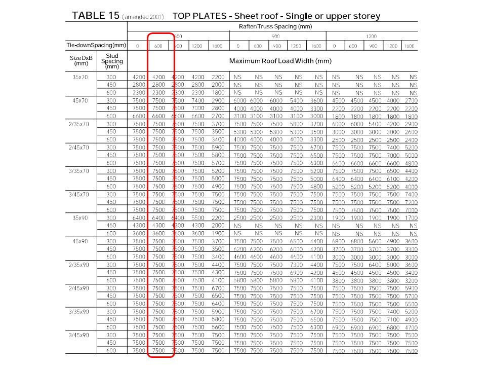
Frame Components To Plate Sizing
Top plate sizing is dependent (See pages 3 to 6 of Handout) Positioning of Rafter/Truss (See next Slide) Upper or Lower Level (Pages 3 & 4 v Pages 5 & 6) Timber Grade – Strength of Timber Roof Material – Tile v Metal Rafter/Truss Spacing – How & Where the Load is applied Stud Spacing – How much bending will be caused by Rafters Roof Load Width - How wide is the Building (see next slide) Span Tables supplied – Identify Part
 Positioning of Rafter/Truss (See next Slide) Upper or Lower Level (Pages 3 & 4 v Pages 5 & 6) Timber Grade – Strength of Timber. Roof Material – Tile v Metal. Rafter/Truss Spacing – How & Where the Load is applied. Stud Spacing – How much bending will be caused by Rafters. Roof Load Width - How wide is the Building (see next slide) Span Tables supplied – Identify Part.")
112
Frame Components To Plate Sizing
Top plate sizing is dependent (See pages 3 to 6 of Handout) (Pages 3 & 4 v Pages 5 & 6) Timber Grade – Strength of Timber Location – Single Level , Upper Level or Lower of 2 Storey Roof Material – Tile v Metal Rafter/Truss Spacing – How & Where the Load is applied Tie Down Spacing – Bending imposed on Top Plate by Uplift Stud Spacing – How much bending will be caused by Rafters Roof Load Width - How wide is the Building (see next slide)
 (Pages 3 & 4 v Pages 5 & 6) Timber Grade – Strength of Timber. Location – Single Level , Upper Level or Lower of 2 Storey. Roof Material – Tile v Metal. Rafter/Truss Spacing – How & Where the Load is applied. Tie Down Spacing – Bending imposed on Top Plate by Uplift. Stud Spacing – How much bending will be caused by Rafters. Roof Load Width - How wide is the Building (see next slide)")
113
Worked Example Roof Material Sheet Roof Location Single Storey
Rafter / Truss Spacing 600mm Tie Down Spacing 600mm Stud Spacing 450mm Roof Load Width 6000mm

114
Worked Example Roof Material Sheet Roof Location Single Storey
Rafter / Truss Spacing 600mm Tie Down Spacing 600mm Stud Spacing 450mm Roof Load Width 6000mm

116
Worked Example Roof Material Sheet Roof Location Single Storey
Rafter / Truss Spacing 600mm Tie Down Spacing 600mm Stud Spacing 450mm Roof Load Width 6000mm

118
Worked Example Roof Material Sheet Roof Location Single Storey
Rafter / Truss Spacing 600mm Tie Down Spacing 600mm Stud Spacing 450mm Roof Load Width 6000mm

120
Worked Example Roof Material Sheet Roof Location Single Storey
Rafter / Truss Spacing 600mm Tie Down Spacing 600mm Stud Spacing 450mm Roof Load Width 6000mm

122
Worked Example Roof Material Sheet Roof Location Single Storey
Rafter / Truss Spacing 600mm Tie Down Spacing 0 Stud Spacing 450mm Roof Load Width 6000mm

123
70 x 45 90 x 45

124
Confirmation of Learning
Determine Minimum Member Size Based on Following Data Roof Material Sheet Roof Location Single Storey Rafter / Truss Spacing 600mm Tie Down Spacing 0 Stud Spacing 600mm Roof Load Width 5500mm Wall Frame Width 70mm Minimum Size ______________________

125
Confirmation of Learning - Answer
Determine Minimum Member Size Based on Following Data Roof Material Sheet Roof Location Single Storey Rafter / Truss Spacing 600mm Tie Down Spacing 0 Stud Spacing 600mm Roof Load Width 5500mm Wall Frame Width 70mm Minimum Size 70 x 45

126
Undersize Top Plate

127
Undersize Top Plate

128
Plates Seasoned timbers are dressed therefore trenching not required
Rough Sawn Timbers such as Oregon, Hardwood require trenching. Housing of plates for studs provides a constant thickness Trenching keeps Top & Bottom plates parallel Restrains Unseasoned Studs from twisting

129
Trenching usually appox 10 mm
Trenching depth is not critical but what is left on is. Top Plates fully supported on masonary walls will be sized based on a 300mm spacing

130
Joining of Plates Where plates are butt jointed they may be joined using a connector plate.

131
Joining of Plates Plates may be Scarfed or Lapped jointed.
Theses are time consuming and rarely used

132
Calculate Plate Lengths
During Fabrication Top & Bottom Plates are the same length Plates should be as long as possible Consider manpower available to stand frames Remember Top Plate must be continuous

133
Roof Load Width AS Definition

134
Roof Load Width Why is it an Important Consideration?

135
Roof Load Width Why is it an Important Consideration?
Compare if Y= 5m & b = 0.6m

136
Roof Load Width Why is it an Important Consideration?
The Top Plate in the Top example is taking more load B = 2 = 5.6m Compare if Y= 5m & b = 0.6m B = 6 = 1.433m

137
Uplift Uplift is a complex item and dealt with at Cert IV level
Generally in Sydney for a Tile Roof it is not a consideration (See next slide) except for; Ocean Front Top of a Hill Isolated Buildings with no wind shielding
 except for; Ocean Front. Top of a Hill. Isolated Buildings with no wind shielding.")
139
Basic Frame Components
Refer page 2 TAFE Guide

140
Lintels Also referred to as a Head when it is not supporting Structural Loads Horizontal Load Bearing Member between Studs Purpose is to transfer structural loads that are above an opening to load bearing studs May be made of many materials - Timber - Engineered Timbers - LVL’s, I Beams - Structural Steel or Cold Rolled Steel Sections

141
Lintels – Installation Requirements
AS 1684 Figure 6.9 page 64

142
Lintels – Installation Requirements
AS 1684 Figure 6.9 page 64

143
Lintels – Installation Requirements
AS 1684 Figure 6.9 page 64

144
Lintels – Installation Requirements
AS 1684 Figure 6.9 page 64

145
From experience this is my preferred method as if there is
A change in size or height, it does not require a major alteration It is a simple change of the infill head.

146
Lintels – Requirement for Top Plate
Top Plate must be Continuous The Top Plate CANNOT be cut To fit a Lintel

147
Frame Components Lintel Sizing
Lintel sizing is dependent (See pages 9 & 10 of Handout) Timber Grade – Strength of Timber Roof Material – Tile v Metal Location – Upper,Single or Lower Level of 2 Storey Floor Load Width– Applicable to Lowers Storey of 2 Storey Only Roof Load Width - How wide is the Building Rafter Truss Spacing – Loading on Beam Lintel Span – Required Span Span Tables supplied – Identify Part
 Timber Grade – Strength of Timber. Roof Material – Tile v Metal. Location – Upper,Single or Lower Level of 2 Storey. Floor Load Width– Applicable to Lowers Storey of 2 Storey Only. Roof Load Width - How wide is the Building. Rafter Truss Spacing – Loading on Beam. Lintel Span – Required Span. Span Tables supplied – Identify Part.")
148
Worked Example

149
Worked Example Timber Grade – MGP10 Roof Material – Tile
Location – Single Level Floor Load Width– Roof Load Width – Rafter Truss Spacing – Lintel Span –

151
Worked Example Timber Grade – MGP10 Roof Material – Tile
Location – Single Level Floor Load Width – N/A Roof Load Width – 3500mm Rafter Truss Spacing – Lintel Span –

153
Worked Example Timber Grade – MGP10 Roof Material – Tile
Location – Single Level Floor Load Width – N/A Roof Load Width – 3500mm Rafter Truss Spacing – 600mm Lintel Span –

155
Worked Example Timber Grade – MGP10 Roof Material – Tile
Location – Single Level Floor Load Width – N/A Roof Load Width – 3500mm Rafter Truss Spacing – 600mm Lintel Span – 2100mm

157
6. Noggins

158
6. Noggins Stop Studs from Twisting, Cupping etc
Assist Studs to take load – prevent buckling under load Form Part of Bracing System

159
6.Noggins Walls > 1350mm in height must have noggins
Max Spacing between rows = 1350mm No Stress grading required Min 25mm Thick Noggins may be offset 2 x Thickness to allow for ease of Installation Min width = Wall Thickness – 25mm

160
Confirmation of Learning
How many Rows of Noggins are required for following wall heights. 2550 3000 3800 Is a 70 x 35 Noggin suitable for a 90mm Wall Frame

161
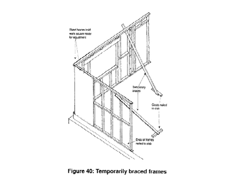
Bracing

162
6. Bracing Member that prevents distortion of frame by Racking Forces
You must determine Wind load on Building

163
Bracing There are many materials that can be used to Brace a wall frame. These generally form part of a system. See page 4 of TAFE Notes

164
Diagonal Timber Bracing
Rarely Used Today.

165
Diamond Bracing Not Mentioned in AS 1684.2.
Must be Considered an Alternative Solution. Would require an Engineer to Certify.

166
Perforated Metal Angle
Where there a 2 in a wall, They should oppose each other

167
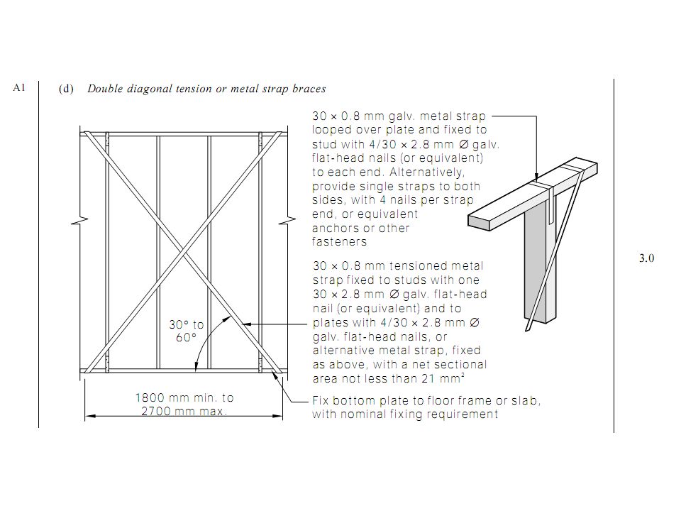
Hoop Iron Cross Bracing
A very good and efficient method and should be 1st choice

168
Hoop Iron Cross Bracing
Tensioning should be done during the hottest part of the day

169
Hoop Iron Cross Bracing
Final Nailing off should be done as late as possible Leave temporary bracing as long as possible

170
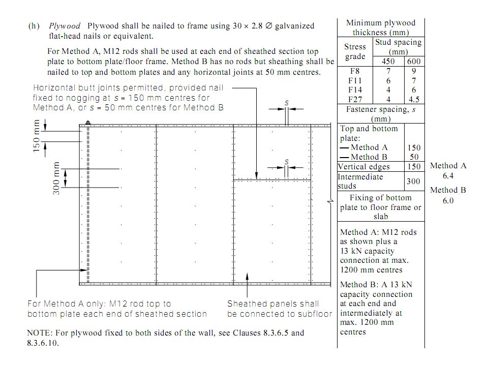
Sheet Bracing Plywood or Hardboard (Masonite)
")
171
6. Bracing Member that prevents distortion of frame by Racking Forces
Section 8 of Standard

173
(a) Determine Wind Classification
 Determine Wind Classification")
174
Limitations of Classification

175
Same Limitations AS

176
(a) Determine Wind Classification
AS 4055 Outline the Process to Determine Geographic Wind Speed Terrain Category Topographic Class Shielding

177
(a) Determine Wind Classification
AS 4055 Outline the Process to Determine Geographic Wind Region Terrain Category Topographic Class Shielding

178
1.Geographic Wind Region

179
Exercise What Region are the following Cities or towns located in
Sydney ______________ Brisbane ______________ Melbourne ______________ Darwin ______________ Perth ______________ Grafton (NSW) ______________ Townsville (Qld) ______________ Alice Springs (NT) ______________ Perisher Valley (NSW) ______________ Launceston (TAS) ______________ Port Hedland (WA) ______________
 ______________. Townsville (Qld) ______________. Alice Springs (NT) ______________. Perisher Valley (NSW) ______________. Launceston (TAS) ______________. Port Hedland (WA) ______________.")
180
Exercise - Answer What Region are the following Cities or towns located in Sydney A Brisbane B Melbourne A Darwin C Perth A Grafton (NSW) B Townsville (Qld) C Alice Springs (NT) A Perisher Valley (NSW) A Launceston (TAS) A Port Hedland (WA) D
 B. Townsville (Qld) C. Alice Springs (NT) A. Perisher Valley (NSW) A. Launceston (TAS) A. Port Hedland (WA) D.")
181
(a) Determine Wind Classification
AS 4055 Outline the Process to Determine Geographic Wind Speed Terrain Category Topographic Class Shielding

182
2.Terain Category

183
2.Terain Category

184
Exercise Determine The Follow Terrain Categories
An Isolated House at Woomera with no significant Topographical features for 15km in all directions. Classification _________________ A House at Bronte located on the Ocean Front. Classification _________________ House Build adjacent to Richmond Air force Base A house in Alexandria (NSW)
")
185
Exercise - Answer Determine The Follow Terrain Categories
An Isolated House at Woomera with no significant Topographical features for 15km in all directions. Classification TC1 A House at Bronte located on the Ocean Front. Classification TC2 House Build adjacent to Richmond Air force Base A house in Alexandria (NSW) Classification TC3
 Classification TC3.")
186
(a) Determine Wind Classification
AS 4055 Outline the Process to Determine Geographic Wind Speed Terrain Category Topographic Class Shielding

187
3. Topographic Class Topographic class determines the effect of wind on a house considering its location on a, hill, ridge or escarpment and the height and average slope of the hill, ridge or escarpment.

188
3. Topographic Class Where average slope is
Greater than 1 in 20 is the Start of the “Hill” .

189
3. Topographic Class Height of Hill.

190
3. Topographic Class Height of Hill. Note Parameter for Escarpment

191
3.Topographic Class AS

192
Topography for Hills Explained

193
Determine Average Slope
The average slope of a hill, ridge or escarpment (φa) shall be the slope measured by averaging the steepest slope and the least slope through the top half of the hill, ridge or escarpment.
 shall be the slope measured by. averaging the steepest slope and the least slope through the top half of the hill, ridge or. escarpment.")
194
AS 4055 - Table 2.3 Row 1 Average Slope < 1 in 10 T1 All Heights T1

195
AS 4055 - Table 2.3 Row 2 Average Slope < 1 in 10 & > 1 in 7.5
*Less than 20m all T1

196
AS 4055 - Table 2.3 Row 3 Average Slope < 1 in 7.5 & > 1 in 5
*H > 30 T3 *H ≤ 30 T2 T1 T1 *Less than 9m all T1

197
AS 4055 - Table 2.3 Row 4 Average Slope < 1 in 5 & > 1 in 3
H > 30 T4 H ≤ 30 T3 T2 H T1

198
AS 4055 - Table 2.3 Row 5 Average Slope > 1 in 3 H > 30 T5

199
Topography for Escarpments Explained

200
3.Topographic Class AS

201
Determine Average Slope
The average slope of a hill, ridge or escarpment (φa) shall be the slope measured by averaging the steepest slope and the least slope through the top half of the hill, ridge or escarpment.
 shall be the slope measured by. averaging the steepest slope and the least slope through the top half of the hill, ridge or. escarpment.")
202
AS 4055 - Table 2.3 Row 1 Average Slope < 1 in 10 T1 T1 T1
All Heights T1

203
AS 4055 - Table 2.3 Row 2 Average Slope < 1 in 10 & > 1 in 7.5
*Less than 20m all T1

204
AS 4055 - Table 2.3 Row 3 Average Slope < 1 in 7.5 & > 1 in 5
*H > 30 T3 *H ≤ 30 T2 T1 T1 T1 *Less than 9m all T1

205
AS 4055 - Table 2.3 Row 4 Average Slope < 1 in 5 & > 1 in 3
H > 30 T4 H ≤ 30 T3 T2 T2 H T1

206
AS 4055 - Table 2.3 Row 5 Average Slope > 1 in 3 H > 30 T5

207
Worked Example For Our Purposes in this course we will always use T1
You will go into more detail in the CERT IV Course

208
(a) Determine Wind Classification
AS 4055 Outline the Process to Determine Geographic Wind Speed Terrain Category Topographic Class Shielding

209
4.Shielding The affect of local obstructions on wind flow
The 5 year likely impact must be considered Growth of Trees etc. Proposed Developments etc. Classes Full Shielding (FS) Partial Shielding (PS) No Shielding (NS)
 Partial Shielding (PS) No Shielding (NS)")
210
Full Shielding (FS) Surrounded by 2 Rows of Houses
Heavily Wooded Areas (Zones A & B Only) Typical Suburb consisting of 10 houses per Ha Roads or Parks less than 100m wide are ignored
 Typical Suburb consisting of 10 houses per Ha. Roads or Parks less than 100m wide are ignored.")
211
Partial Shielding (PS)
2.5 Houses, Trees, Sheds etc. per Ha In Regions C & D heavily wooded areas

212
No Shielding (NS) No Permanent Obstructions
Less than 2.5 obstructions per Ha First 2 Rows abutting Open Parkland, Open Water, Airfield etc.

213
Worked Examples

215
Wind Classification

216
Worked Example TAFE UNI Randwick Town Centre

217
Worked Example Geographic Wind Region Region A

218
Worked Example Geographic Wind Region Region A Topography T1
House is not On a hill

219
Worked Example Geographic Wind Region Region A Topography T1
Shielding FS Shielded by 2 Rows of Houses

220
Worked Example Geographic Wind Region Region A Topography T1
Shielding FS Terrain Category TC 3

221
Worked Example Geographic Wind Region Region A Topography T1
Shielding FS Terrain Category TC 3

222
Worked Example Geographic Wind Region Region A Topography T1
Shielding FS Terrain Category TC 3

223
Worked Example Geographic Wind Region Region A Topography T1
Shielding FS Terrain Category TC 3

224
Worked Example Geographic Wind Region Region A Topography T1
Shielding FS Terrain Category TC 3 Wind Category is N1

225
Worked Example Bronte Ocean Front

226
Worked Example Geographic Wind Region Region A

227
Worked Example Geographic Wind Region Region A Topography T5
House is located on top Of 30m escarpment

228
Worked Example Geographic Wind Region Region A Topography T5
Shielding NS No Shielding on Ocean Side – You must always use worst case example

229
Worked Example Geographic Wind Region Region A Topography T5
Shielding NS Terrain Category TC1

230
Worked Example Geographic Wind Region Region A Topography T5
Shielding NS Terrain Category TC1

231
Worked Example Geographic Wind Region Region A Topography T5
Shielding NS Terrain Category TC1

232
Worked Example Geographic Wind Region Region A Topography T5
Shielding NS Terrain Category TC1

233
Worked Example Geographic Wind Region Region A Topography T5
Shielding NS Terrain Category TC1 Wind Category = N5

235
Determine Wind Pressure
Determined by; Wind Classification Tables 8.1 to 8.5 AS Is dependant on the shape of the Building Is it a Gable or Hip or a more Complex shape? – Explained in Next Slides

242
Area of Elevation Table 8.2 h = ½ height of the wall (half of the floor to ceiling height). For wind direction 2, the pressure on the gable end is determined from Table 8.1 pressure on the hip section of the elevation is determined from Table 8.2. The total of racking forces is the sum of the forces calculated for each section. Eaves < 1m2 can be ignored. Table 8.1 Table 8.2 Table 8.2 Table 8.2

243
Area of Elevation You must determine Area of each part of the
11000 You must determine Area of each part of the elevation Of the Building. 7000 15000 6000 8000 5000

244
Area of Elevation Wind Direction 1 has 2 Shapes 1.1 = 14m2 1.2 = 16m2

246
(d) Calculating Racking Force
Formula Area of Elevation x Wind Pressure Required Data Pitch = 30°

247
(d) Calculating Racking Force
Racking Force = Area x Wind Pressue Wind Direction 1 has 2 Shapes 1.1 = 14m2 x Wind Pressure ? 1.2 = 16m2 2 1 6000 5000 Wind Direction 2 has 2 Shapes 1.1 = 14m2 1.2 = 14m2 2 1

248
Wind Pressure Direction 1.1

249
(d) Calculating Racking Force
Racking Force = Area x Wind Pressue Wind Direction 1 has 2 Shapes 1.1 = 14m2 x 0.75 = 10.5 1.2 = 16m2 x Wind Pressure ? 2 1 6000 5000 Wind Direction 2 has 2 Shapes 1.1 = 14m2 1.2 = 14m2 2 1

250
Wind Pressure Direction 1.2

251
(d) Calculating Racking Force
Racking Force = Area x Wind Pressue Wind Direction 1 has 2 Shapes 1.1 = 14m2 x 0.75 = 10.5 1.2 = 16m2 x 0.74 = 11.84 Total Racking Force = 22.34 2 1 6000 5000 Wind Direction 2 has 2 Shapes 1.1 = 14m2 x Wind Pressure ? 1.2 = 14m2 2 1 8000 7000

252
Important Note Which Wind Pressure to Use ? Wind N2
8 000 Pitch 25° 15 000 As shape is the same from both directions We use the same Table (8.2)
")
253
Pressure = 0.73 in Both Directions

254
Important Note Which Wind Pressure to Use ? Wind N2
8 000 Pitch 25° Table 8.1 Table 8.2 15 000 As shape is different in each elevation we must determine individually for each direction And use WORST case.

255
Pressure = 0.92

256
Pressure = 0.71

257
Important Note Which Wind Pressure to Use ? Wind N2
The Gable End will ALWAYS have the highest pressure 8 000 Pitch 25° Table 8.2 = 0.71 Table 8.1 = 0.92 15 000 As the worst case is the Gable End, we must use the wind Pressure from Table 8.1 = 0.92

258
Pressure = 0.71

259
(d) Calculating Racking Force - Revisited
Racking Force = Area x Wind Pressue Wind Direction 1 has 2 Shapes 1.1 = 14m2 x 0.75 = 10.5 1.2 = 16m2 x 0.74 = 11.84 Total Racking Force = 22.34 2 1 6000 5000 Wind Direction 2 has 2 Shapes 1.1 = 14m2 x Wind Pressure ? 1.2 = 14m2 2 1

260
Wind Pressure Direction 1.2
You must use this table as it is a Gable End

261
(d) Calculating Racking Force
Racking Force = Area x Wind Pressue Wind Direction 1 has 2 Shapes 1.1 = 14m2 x 0.75 = 10.5 1.2 = 16m2 x 0.74 = 11.84 Total Racking Force = 22.34 2 1 6000 5000 Wind Direction 2 has 2 Shapes 2.1 = 14m2 x 0.92 = 12.88 2.2 = 14m2 x Wind Pressure ? 2 1 8000 7000

262
Wind Pressure Direction 2.2

263
(d) Calculating Racking Force
Racking Force = Area x Wind Pressue Wind Direction 1 has 2 Shapes 1.1 = 14m2 x 0.75 = 10.5 1.2 = 16m2 x 0.74 = 11.84 Total Racking Force = 22.34 2 1 6000 5000 Wind Direction 2 has 2 Shapes 2.1 = 14m2 x 0.92 = 12.88 2.2 = 14m2 x 0.72 = 10.08 Total Racking Force = 22.96 2 1 8000 7000

264
Before we do this lets see what (f) says
 says")
265
Before we do this lets see what (f) says
 says")
266
Clause 8.3.6.6 We must start placing Bracing at, External Walls &
At Corners

267
Before we do this lets see what (f) says
 says")
268
Clause 8.3.6.7 Single or Upper Level Bracing
Max Spacing is 9m for N2 & N2 Wind Classification For N3 & above refer Tables

271
Before we do this lets see what (f) says
 says")
272
Table 8.18 List Types of Bracing Systems that are “Deemed to Satisfy”
Gives a value per/m length of Bracing Panel Theses values are used to counteract the Racking Forces calculated.

286
Before we do this lets see what (f) says
 says")
287
Clause &Table 8.19

288
Lets Design

289
Design Wind Direction 1.1 Racking Force = 10.5 Wind Direction 1.2
3500 Wind Direction 2.1 Racking Force = 12.88 7000 3500 4500 6000 3000 Wind Direction 2.2 Racking Force = 10.08 8000 3000 5000

290
Nominal Wall Bracing

291
Design – Area 1.1 Wind Direction 1.1 Racking Force = 10.5 3500 7000
4500 6000 3000 8000 3000 5000

292
Design – Area 1.1 Wind Direction 1.1 Racking Force = 10.5
Metal Cross Strapping to Corners As per Table 8.14 (b) 3500 7000 3500 4500 6000 3000 Note you must do all corners Regardless of Overkill 8000 3000 5000
 Note you must do all corners. Regardless of Overkill")
293
Design – Area 1.1 Wind Direction 1.1 Racking Force = 10.5
Metal Cross Strapping to Corners As per Table 8.14 (b) 3500 7000 3500 4500 6000 3000 You Still would place Bracing on Internal Walls To assist During Constructions Using any Method (a) is easiest 8000 3000 5000
 You Still would place. Bracing on Internal Walls. To assist During Constructions. Using any Method (a) is easiest")
294
Design – Area 1.1 Wind Direction 1.1 Racking Force = 10.5
Metal Cross Strapping to Corners As per Table 8.14 (b) 3500 7000 3500 4500 6000 3000 You Still would place Bracing on Internal Walls To assist During Constructions Using any Method (a) is easiest 8000 3000 5000
 You Still would place. Bracing on Internal Walls. To assist During Constructions. Using any Method (a) is easiest")
295
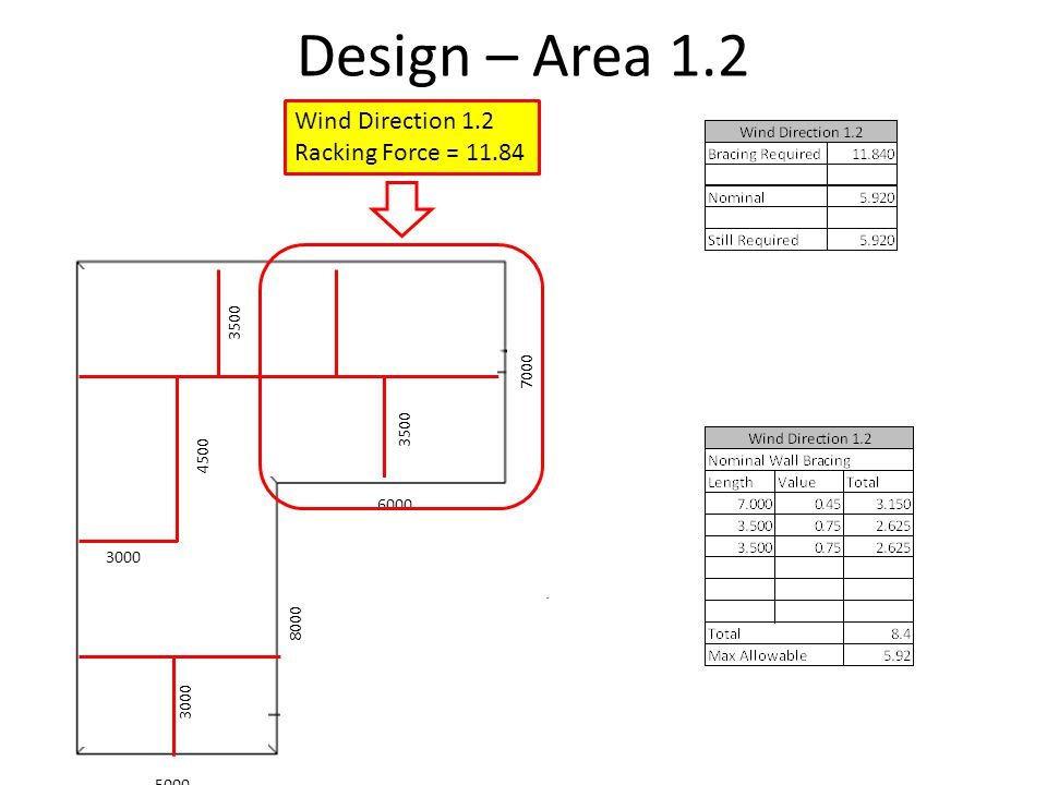
Design – Area 1.2 Wind Direction 1.2 Racking Force = 11.84 3500 7000
4500 6000 3000 8000 3000 5000
296
Design – Area 1.2 Wind Direction 1.2 Racking Force = 11.84
3500 7000 3500 4500 6000 3000 8000 Metal Cross Strapping to Corners As per Table 8.14 (b) 3000 5000
")
297
Design – Area 1.2 Wind Direction 1.2 Racking Force = 11.84
3500 7000 3500 4500 6000 3000 Bracing to Internal Walls to Spread Bracing thru Structure Assist During Construction 8000 3000 5000

298
Design – Area 2.1 Wind Direction 2.1 Racking Force = 12.88 3500 7000
4500 6000 3000 8000 3000 5000

299
Design – Area 2.1 Wind Direction 2.1 Racking Force = 12.88
3500 Wind Direction 2.1 Racking Force = 12.88 7000 3500 4500 6000 3000 8000 Metal Cross Strapping to Corners As per Table 8.14 (b) 3000 5000
")
300
Design – Area 2.1 Wind Direction 2.1 Racking Force = 12.88
3500 Wind Direction 2.1 Racking Force = 12.88 7000 3500 4500 6000 3000 8000 Bracing to Internal Walls to Spread Bracing thru Structure Assist During Construction 3000 5000

301
Design – Area 2.2 Wind Direction 2.2 Racking Force = 10.08 3500 7000
4500 6000 3000 Wind Direction 2.2 Racking Force = 10.08 8000 3000 5000

302
Design – Area 2.2 Wind Direction 2.2 Racking Force = 10.08 3500 7000
4500 6000 3000 Wind Direction 2.2 Racking Force = 10.08 8000 3000 5000

303
Design – Area 2.2 Bracing to Internal Walls to
3500 7000 3500 4500 6000 3000 8000 Bracing to Internal Walls to Spread Bracing thru Structure Assist During Construction 3000 5000

304
Lets Design

305
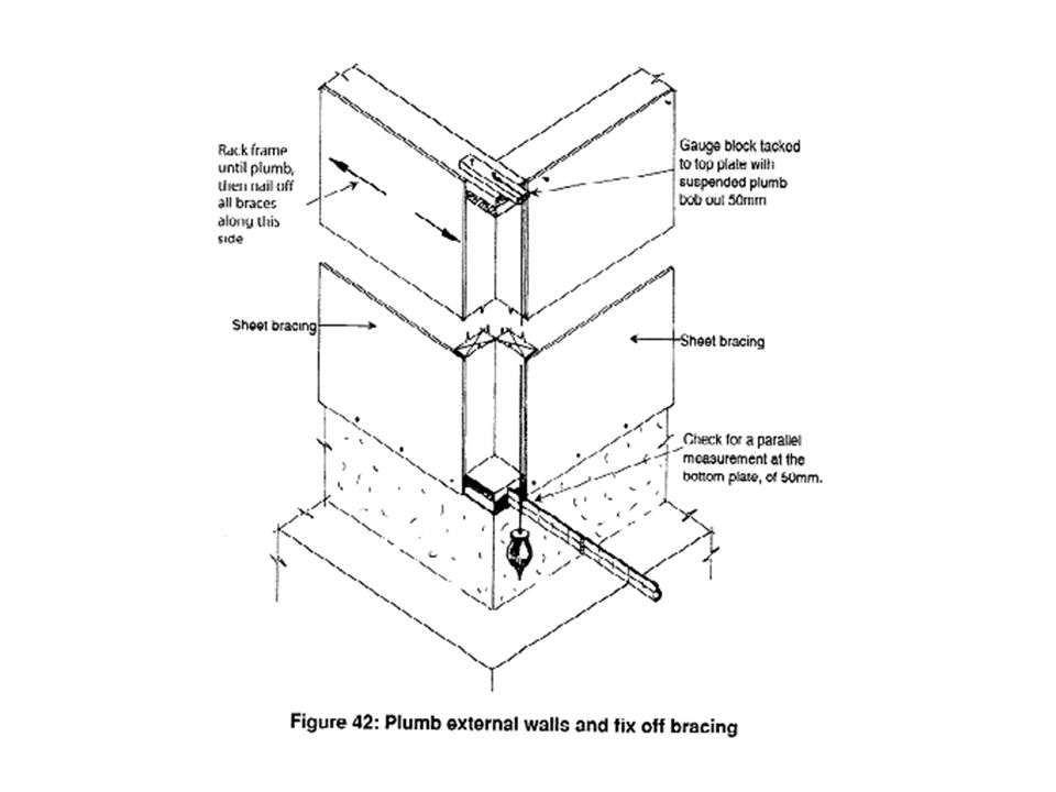
Clause Top of INTERNAL Bracing Walls must be fixed to Ceiling or Upper Floor Structure with equivalent Shear Capacity as to its Bracing Capacity

306
See Next Slide for Explanation

307
Confirmation Learning
Complete Exercise 42 of your workbook

308
Connection of Internal Brace Walls
In our Exercise we use Crossed Hoop Iron 3500 7000 3500 4500 6000 3000 Bracing Value = 1.5 Bracing Panel Length = 2.7 Total Force = 1.5 x 2.7 = 4.05kN 8000 3000 5000

309
Total Force = 4.05kN Seasoned Radiata Pine = JD4 1 Fixing at each end of Bracing Panel = 2 x 2.1kN = 4.2 (Sufficient)
")
311
Wall Frames Frames are classified into 2 categories
Load Bearing – They are structural frames, they transfer loads from roof or upper floor to the supporting floor frame. They can be either external or internal walls. Non Load Bearing – - do not support any structural loads. - They support their own weight - Non structural loads doors and frame, kitchen cupboards, driers etc. - support some live loads eg Doors closing. Therefore there are some minimum requirements for these AS cl 6.3.5

312
AS cl 6.3.5

313
Wall Components

314
Trimmers Horizontal members fixed between window studs and door studs.
Referred to as Sill or Head trimmers Usually of the same section size bottom plates Openings wider than 1800mm require trimmers as specified in AS cl & table 6.3

315
Trimmers Refer Table 6.3 of your Australian Standard

316
Trimming Studs Run from Trimmers to Plates – Use same Timber Size
Used to block out Narrow Lintel Where use in conjunction with Lintel they may take structural loads Must be same depth as wall frame to accept finishes May also be referred to as “Jack”, “Soldier”, or “Short” studs

317
Wall Intersections Blocking
Placed at intersections of wall frames Normally 3 Blocks per intersection

318
Blocking AS1684.2

319
What is a Concentrated Load ?
>3000

322
Stress Grading Refers to the Timbers Strength
Timber must be able to withstand stress loads placed on them. Overloading may cause straining or failure 3 types of stress Compressive Tensile Shear Note Torsional Stress is not discussed

325
Stress Grading Members Sizes will be determined for span tables
Generally for Residential Construction sizes will not be specified by designers Why? Architect will not want to take responsibility Engineer will want to charge extra to do this and Why would a client want to pay for something that he can get done for nothing

326
Stress Grading Why are members generally specified on Commercial projects AS Residential Timber Framed Construction Guide

328
AS Limitations 1.4.4 The Maximum number of storey's of timber shall not exceed 2 1.4.5 The maximum width of a building shall mm, Note, if you use AS simplified max width = mm The maximum wall height shall be 3000mm excluding gable ends 1.4.7 The maximum roof pitch shall be 35 degrees

330
Ordering Timber Timber is ordered in lineal meters may be priced in cubic meters Increments of 300mm Timber should be ordered as required - avoid unnecessary exposure to weather - affecting cash flows - theft - storage

331
Material Storage Timber should be stored on gluts
This allows for airflow Care should be taken in stack sizes Stacks can be strapped for safety

332
Storage of Materials Timber should be stored as close as possible to work area

340
Stud Spacing – Other Consideration
Stud Spacing may also be determined by sheeting

341
Studs Not all external sheeting require critical stud placement
Check with LATEST manufactures manual as to requirements

343
Harditek (Blue Board) For Sheet Products Stud Placement is Important
 For Sheet Products Stud Placement is Important")
344
Calculating Stud Lengths
Finished Floor to Ceiling govern stud length Minimum Habitable Room is 2400mm Clear Floor Finishes 1. Carpet 20mm 2. Timber Flooring 40mm (Depending on Batten) Ceilings 1. 10mm Plasterboard 2. 13mm Plasterboard
 Ceilings 1. 10mm Plasterboard 2. 13mm Plasterboard.")
345
Calculating Stud Length
Double Storey building may have FFL (Finished Floor Level). Allowance must be made for structural members Most Importantly Determine if there are any height restrictions Type of Roof Will affect Stud Heights
. Allowance must be made for structural members. Most Importantly Determine if there are any height restrictions. Type of Roof Will affect Stud Heights.")
346
Top & Bottom Plates = 90 x 45 F5 Step 1 – Determine Floor & Ceiling Floor Carpet = 20mm Ceiling Gyprock = 13mm Step 2 – Calculate Stud Length Minimum Clearance = 2400mm Plus Flooring = mm Plus Ceiling = mm Wall Height = 2440mm less Wall Plates = mm Stud Length = 2350mm

347
Ground Fl Finish = Timber (40mm) First Floor = Carpet (20mm)
Upper Level Joists = 200 x 50 F5 Top & Bottom Plates = 90 x 45 Step 1- Determine SFL (Structural Floor Level) SFL First Floor = (FFL First Fl) -20 (Carpet) SFL= SFL Ground Fl = (FFL Gnd) - 40 (Timber) SFL = Step 2 – Calculate Height Difference SFL First Floor = – SFL Ground Fl = Height Difference = Ground Floor First Floor
 SFL First Floor = (FFL First Fl) -20 (Carpet) SFL= SFL Ground Fl = (FFL Gnd) - 40 (Timber) SFL = Step 2 – Calculate Height Difference. SFL First Floor = – SFL Ground Fl = Height Difference = Ground Floor. First Floor.")
348
Step 3 – Structural Elements Height Diff = 2.750 Less Flooring = 0.017
Less Floor Joist = 0.200 Less T & B Plate = 0.090 Stud Length = 2.443 Ground Floor First Floor

349
Carpet Both Floors (20mm) Ceilings 10mm Plasterboard (Allow 20mm)
Dimensions are clear measurements Lower level plates Upper Level Plates Bottom Plate = 90 x 35 F5 Bottom Plate = 90 x 45 F5 Top Plate = 90 x 45 F5 Top Plate = 90 x 70 F5

350
Calculating Door Heights
On Concrete Slab Using a standard 2040mm x 820mm Allow 22mm for Carpet (17mm + 5mm) 2040 mm Door Height 2mm Clearance between Door & Jamb 20mm for Jamb 10mm Clearance between Jamb & Head 15mm Clearance between Jamb & Lintel Total = 2094mm Say 2100mm
 2040 mm Door Height. 2mm Clearance between Door & Jamb. 20mm for Jamb. 10mm Clearance between Jamb & Head. 15mm Clearance between Jamb & Lintel. Total = 2094mm Say 2100mm.")
351
Calculation of Door Width

352
Calculation of Window Check with manufacturer if windows are not on site Generally at same height of doors Check on elevations for window heights 15mm Clearance between Jamb & Lintel Allow 10mm under sill

353
Window Width Care should be taken when setting out to brick bond!
Client may want window to line up with internal fitting Client may want window dead center of room

357
Lintels

362
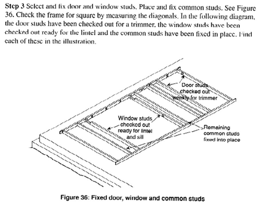
Construct Wall Frames Number Wall Frames Clock Wise Direction
Internal Walls Left to Right Top To Bottom

363
Setting Out Plates Confirm Dimensions of Slab/ Subfloor Select Suitable Timber & Cut to Length Tack Together Mark Appropriate ID Number on Plate Mark Required Studs – In Following Order End Studs Wall Intersections Openings Common Studs

364
Setting Out Plates If required prepare a storey rod with the appropriate markings (ie Horizontal & Vertical Bond) Set out position of window and doors studs remembering to allow for required jamb studs If required adjust position to match brickbond Set out Common Studs, Jack Studs at required spacing

365
Preparing Studs Use Storey Rod (Pattern Stud) to cut required studs
Mark and check out window and door studs

366
Fixing Wall Frames To Floors
AS

367
Wall Frame Assembly What are Advantages & Disadvantages of Prefabricated Wall Frames?

368
Assembling Wall Frames

374
Frame Erection

379
Nominal Fixings For Bottom Plates AS 1684.2

Similar presentations