Download presentation
Presentation is loading. Please wait.

1
Computer and Information Sciences College / Computer Science Department CS 206 D Computer Organization and Assembly Language

2
Computer and Information Sciences College / Computer Science Department Chapter 2 MICROCOMPUTER ARCHITECTURE 2

3
2.1 Basic Blocks of a Microcomputer 2.2 Typical Microcomputer Architecture 2.3 Single-Chip Microprocessor 2.4 Program Execution by Conventional Microprocessors 2.5 Program Execution by typical 32-bit Microprocessors 2.6 Scalar and Superscalar Microprocessors 2.7 RISC vs. CISC Outline 3

4
A microcomputer has three basic blocks: 1. A central processing unit (CPU) 2. A memory unit (RAM & ROM) 3. An input/output (I/O) unit. The CPU(microprocessor) executes all the instructions and performs arithmetic and logic operations on data. A memory unit stores both data and instructions. The memory section typically contains ROM and RAM chips. A system bus (comprised of several wires) connects the these blocks. 2.1 Basic Blocks of a Microcomputer 4
 3. An input/output (I/O) unit. The CPU(microprocessor) executes all the instructions and performs arithmetic and logic operations on data. A memory unit stores both data and instructions. The memory section typically contains ROM and RAM chips. A system bus (comprised of several wires) connects the these blocks. 2.1 Basic Blocks of a Microcomputer 4.")
5
5 In a single-chip microcomputer, these three elements are on one chip. Whereas in a single-chip microprocessor, separate chips are required for memory and I/O.

6
The microcomputer’s system bus contains three buses: Address, Data, and Control bus WRITE operation: when a memory or an I/O chip receives data from the microprocessor and data is written into a selected memory location or an I/O port (register). READ operation : when a memory or an I/O chip sends data to the microprocessor, and data is read from a selected memory location or an I/O port. 2.2.1 System Bus 6

7
The Address Bus Unidirectional bus: Information transfer takes place in only one direction, from the microprocessor to the memory or I/O elements. Typically 20 to 32 bits long. The size of the address bus determines the total number of memory addresses available The data bus bidirectional bus: data can flow in both directions, that is, to or from the microprocessor. The size of the data bus varies from one microprocessor to another. 2.2.1 System Bus For example : microprocessor with 32 address pins can generate 2 32 = 4,294,964,296 bytes 7

8
The control bus consists of a number of signals that are used to synchronize operation of the individual microcomputer elements. Memory read/write signal. I/O read/write signal. Interrupt request. Clock signals. Transfer ACK Bus request Bus grant Interrupt ACK Reset 8 2.2.1 System Bus Is it Unidirectional or bidirectional bus ??

9
Operations Of Bus The operation of the bus is as follows: If one module wishes to send data to another, it must do two things: (1) (1) Obtain the use of the bus. (2) Transfer data via the bus. If one module wishes to request data from another module, it must: (1) Obtain the use of the bus. (2)Transfer a request to the other module over the appropriate control and address lines. It must then wait for that second module to send the data.
 Transfer data via the bus. If one module wishes to request data from another module, it must: (1) Obtain the use of the bus. (2)Transfer a request to the other module over the appropriate control and address lines. It must then wait for that second module to send the data..")
10
The system clock signals are contained in the control bus. The clock frequency f: the number of cycles per second (hertz, abbreviated Hz). Clock frequency (rate): cycles per second Clock cycle = 1/f clock frequency determines the speed of the microcomputer. e.g., 4.0GHz = 4000MHz = 4.0×10 9 Hz Clock period: duration of a clock cycle e.g., 250ps = 0.25ns = 250×10 –12 s 2.2.2 Clock Signals Clock (cycles) Data transfer and computation Update state Clock period
. Clock frequency (rate): cycles per second Clock cycle = 1/f clock frequency determines the speed of the microcomputer. e.g., 4.0GHz = 4000MHz = 4.0×10 9 Hz Clock period: duration of a clock cycle e.g., 250ps = 0.25ns = 250×10 –12 s Clock Signals Clock (cycles) Data transfer and computation Update state Clock period.")
11
The microprocessor is the CPU of the microcomputer The logic inside the microprocessor chip can be divided into three main areas: 1. The arithmetic-logic unit (ALU). 2. The register section. 3. The control unit. 2.3 Single-Chip Microprocessor
. 2. The register section. 3. The control unit. 2.3 Single-Chip Microprocessor.")
12
Basic Blocks of a Computer Components

13
The number, size, and types of registers vary from one microprocessor to another. Basic Microprocessor Registers: Instruction Register IR: stores instructions. The word size of the microprocessor determines it’s size. Program Counter PC/IP: contains the address of the next instruction to be executed. The size of the program counter is determined by the size of the address bus Memory Address Register MAR: contains the address of data. The microprocessor uses that address as a direct pointer to memory. The contents of the address is the actual data that is being transferred. Accumulator. 2.3.1 Registers 13

14
How Program Counter is Work ? 1. Upon activating the microprocessor’s RESET input, the address of the first instruction to be executed is loaded into PC. 2. To execute an instruction, the microprocessor typically places the contents of PC on the address bus and reads (“fetches”) the contents of this address(i.e., instruction) from memory 3. PC contents are incremented automatically by the microprocessor’s internal logic. Microprocessor executes a program sequentially, unless the program contains an instruction such as a JUMP instruction, which changes the sequence. 2.3.1 Registers 14
 the contents of this address(i.e., instruction) from memory 3. PC contents are incremented automatically by the microprocessor’s internal logic. Microprocessor executes a program sequentially, unless the program contains an instruction such as a JUMP instruction, which changes the sequence Registers 14.")
15
General Purpose Register (GPR)/ Accumulator: stores the result after most ALU operations. In 8-bit microprocessors the instructions to shift or rotate the Accumulator one bit to the right or left through the carry flag. In16- and 32-bit microprocessors the accumulator is replaced by a GPR. Any GPR can be used as an Accumulator. GPR can hold data, memory addresses, or the results of arithmetic or logic operations. Most registers are GPR, but some, such as (PC),are provided for dedicated functions 2.3.1 Registers 15
,are provided for dedicated functions Registers 15.")
16
The main purpose of the control unit is to read and decode instructions from the program memory. To execute an instruction, the control unit steps through the appropriate blocks of the ALU based on the op-codes contained in the instruction register. 2.3.2 Control Unit

17
Control Signals RESET: common input to all microprocessors. When this input pin is driven HIGH or LOW, the PC is loaded with a predefined address specified by the manufacturer. READ/WRITE (R/W) : common output to all microprocessors. Tells the other microcomputer elements whether the microprocessor is performing a READ or a WRITE operation. HIGH indicates a READ operation LOW indicates a WRITE operation. 2.3.2 Control Unit 17
 : common output to all microprocessors. Tells the other microcomputer elements whether the microprocessor is performing a READ or a WRITE operation. HIGH indicates a READ operation LOW indicates a WRITE operation Control Unit 17.")
18
Control Signals READY: input to a microprocessor. Slow devices (memory and I/O) use this signal to gain extra time to transfer data to or receive data from a microprocessor. READY is active LOW signal, that is, LOW indicates that the microprocessor is ready. Therefore, when the microprocessor selects a slow device, the device places a LOW on the READY. The microprocessor responds by suspending all its internal operations and enters a WAIT state. When the device is ready to send or receive data, it removes the READY signal. The microprocessor comes out of the WAIT state and performs the appropriate operation. 2.3.2 Control Unit
 use this signal to gain extra time to transfer data to or receive data from a microprocessor. READY is active LOW signal, that is, LOW indicates that the microprocessor is ready. Therefore, when the microprocessor selects a slow device, the device places a LOW on the READY. The microprocessor responds by suspending all its internal operations and enters a WAIT state. When the device is ready to send or receive data, it removes the READY signal. The microprocessor comes out of the WAIT state and performs the appropriate operation Control Unit.")
19
Control Signals Interrupt Request (INT or IRQ). The external I/O devices can interrupt the microprocessor via IRQs. When this signal is activated by the external devices, the microprocessor service IRQ by interrupt service routine. Interrupt service program is written by the user for performing tasks that the interrupting device wants the microprocessor to carry out. After completing this program, the microprocessor returns to the main program it was executing when the interrupt occurred. 2.3.2 Control Unit

20
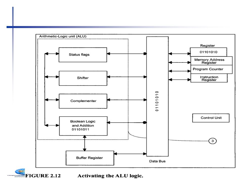
The ALU performs all the data manipulations, such as arithmetic and logic operations, inside a microprocessor. The size of the ALU conforms to the word length of the microcomputer. ALU Functions: 1.Binary addition and logic operations 2. Finding the one’s complement of data 3. Shifting or rotating the contents of a general-purpose register 1 bit to the left or right through a carry 2.3.3 Arithmetic-Logic Unit

21
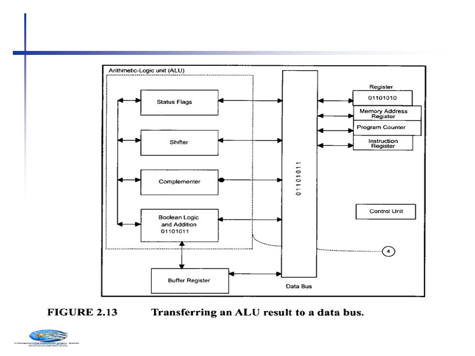
2.3.4 Functional Representations of Simple and Typical Microprocessors Buffer Register : Stores any data read from memory for further processing by the ALU.

22
Typical Microprocessor Pentium I

23
The Pentium contains two instruction pipelines: the U-pipe and the V-pipe. The U-pipe can execute all integer and floating-point instructions. The V-pipe can execute simple integer instructions The Pentium contains two separate cache memories: code cache and data cache. 23 Typical Microprocessor Pentium I

24
The control unit performs two basic operations: 1. instruction interpretation 2. and instruction sequencing. There are two methods for designing a control unit: 2.3.5 Simplified Explanation of Control Unit design

25
2.3.5 Simplified Explanation of Control Unit design How incrementing the contents of the register by 1 is done in microprogramming control ??

30
The three steps for completing the instruction: 1.Fetch: The microprocessor fetches (instruction read) the instruction from the main memory (external to the microprocessor) into the instruction register. 2. Decode: The microprocessor decodes or translates the instruction using the control unit. The control unit inputs the contents of the instruction register, and then decodes (translates) the instruction to determine the instruction type. 3. Execute: The microprocessor executes the instruction using the control unit. To accomplish the task, the control unit generates a number of enable signals required by the instruction. 2.4 Program Execution by Conventional Microprocessors
 the instruction to determine the instruction type. 3. Execute: The microprocessor executes the instruction using the control unit. To accomplish the task, the control unit generates a number of enable signals required by the instruction. 2.4 Program Execution by Conventional Microprocessors.")
31
For example: register R3= register R1 + register R2 A conventional microprocessor performs the following steps: 1. The microprocessor fetches the instruction into IR 2. The control unit CU decodes the contents of IR 3. The CU executes the instruction by generating enable signals for the register and ALU sections to perform the following: a. The CU transfers the contents of registers R1 and R2 from the Register section into the ALU. b. The CU commands the ALU to ADD. c. The CU transfers the result from the ALU into register R3 of the register section. 2.4 Program Execution by Conventional Microprocessors 31

32
Instruction Pipelines Instruction cycle typically involves the following activities: 1. Instruction fetch - needs five clocks to complete 2. Instruction decode 3. Operand fetch (Data Read) 4. Operation execution 5. Result routing. 2.5.1 Pipelining 32
 4. Operation execution 5. Result routing Pipelining 32.")
33
Multi-stage pipeline Pipelining makes it possible for processor to execute instructions in parallel Instruction execution divided into discrete stages Example of a non- pipelined processor. For example, 80386. Many wasted cycles.

34
Pipelined execution More efficient use of cycles, greater throughput of instructions: (80486 started to use pipelining) For k stages and n instructions, the number of required cycles is: k + (n – 1) compared to k*n
 For k stages and n instructions, the number of required cycles is: k + (n – 1) compared to k*n")
35
Basic Concept 2.5.1 Pipelining 35 Hi is Hardware designed to perform activity Ai

36
2.5.1 Pipelining 36

37
Effects of Pipelining

38
Instruction Pipelining

39
Scalar processors such as the 80486 can execute one instruction per cycle. The 80486 contains only one pipeline. Superscalar microprocessors, can execute more than one instruction per cycle. These microprocessors contain more than one pipeline. The Pentium, a superscalar microprocessor, contains two independent pipelines. This allows the Pentium to execute two instructions per cycle. 2.6 Scalar and Superscalar Microprocessors

40
Superscalar A superscalar processor has multiple execution pipelines. In the following, note that Stage S4 has left and right pipelines (u and v). For k states and n instructions, the number of required cycles is: k + n Pentium: 2 pipelines Pentium Pro: 3
. For k states and n instructions, the number of required cycles is: k + n Pentium: 2 pipelines Pentium Pro: 3.")
42
2.7 RISC vs. CISC: two types of microprocessor 42 CISC: Complex Instruction Set Computer RISC: Reduced Instruction Set Computer large number of instructions and many addressing modes One instruction per cycle a simple instruction set with a few addressing modes slower clock ratefast clock rate complex control unit, thus requiring microprogrammed implementation. hardwired control Unit more difficult to pipeline;more efficient pipelining. complex programs require fewer instructions in CISC RISC requires a large number of instructions to accomplish the same task

43
Intel’s original Pentium is a CISC microprocessor. Not clear cut Many designs borrow from both philosophies Intel Pentium Pro and other succeeding members of the Pentium family and Motorola 68060 use a combination of RISC and CISC architectures for providing high performance. 2.7 RISC vs. CISC 43

Similar presentations


 – coordinates the sequencing of steps involved in executing.>")


