Download presentation
Presentation is loading. Please wait.

2
I NTRODUCTION P IN CONFIGARATION O PERATING MODE

4
I ts an I/O port chip used for interfacing I/O devices with microprocessor. T he parallel input-output port chip 8255 is also called as programmable peripheral input-output port 2 4 input/output lines which may be individually programmed in two groups of twelve lines each, or three groups of eight lines. T hey are named as group A, group B, group C

6
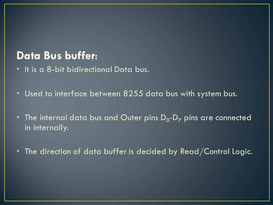
Data Bus buffer: It is a 8-bit bidirectional Data bus. Used to interface between 8255 data bus with system bus. The internal data bus and Outer pins D 0 -D 7 pins are connected in internally. The direction of data buffer is decided by Read/Control Logic.

7
Read/Write Control Logic: This is getting the input signals from control bus and Address bus Control signal are RD and WR. Address signals are A0,A1,and CS. 8255 operation is enabled or disabled by CS.

8
Group A and Group B control: Group A and B get the Control Signal from CPU and send the command to the individual control blocks. Group A send the control signal to port A and Port C (Upper) PC 7 -PC 4. Group B send the control signal to port B and Port C (Lower) PC 3 -PC 0.
 PC 7 -PC 4. Group B send the control signal to port B and Port C (Lower) PC 3 -PC 0..")
9
PORT A: This is a 8-bit buffered I/O latch. It can be programmed by mode 0, mode 1, mode 2. PORT B: This is a 8-bit buffer I/O latch. It can be programmed by mode 0 and mode 1. PORT C: This is a 8-bit Unlatched buffer Input and an Output latch. It is splited into two parts. It can be programmed by bit set/reset operation.

12
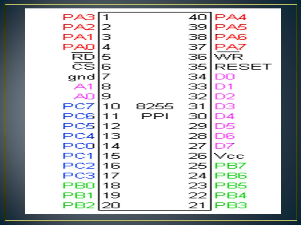
Data bus(D 0 -D 7 ) :These are 8-bit bi-directional buses, connected to 8085 data bus for transferring data. CS: This is Active Low signal. When it is low, then data is transfer from microprocessor RD: This is Active Low signal, when it is Low read operation will be start. Write: This is Active Low signal, when it is Low Write operation will be start.

13
A1A0Select00PA 01PB 10PC 11 Control reg.

14
RESET: This is used to reset the device. That means clear control registers. PA 0 -PA 7 :It is the 8-bit bi-directional I/O pins used to send the data to peripheral or to receive the data from peripheral. PB 0 -PB 7 :Similar to PA PC 0 -PC 7 :This is also 8-bit bidirectional I/O pins. These lines are divided into two groups. 1.PC 0 to PC 3 (Lower Groups) 2.PC 4 to PC 7 (Higher groups)
 2.PC 4 to PC 7 (Higher groups).")
15
BIT SET/RESET MODE: The PORT C can be Set or Reset by sending OUT instruction to the CONTROL registers. The BSR mode will only affect to port C. Set/Reset can be determined by entering certain control word to control register. No change to the previous data when D7 change from 1 to 0; therefore the I/O ports A and B unchanged.

17
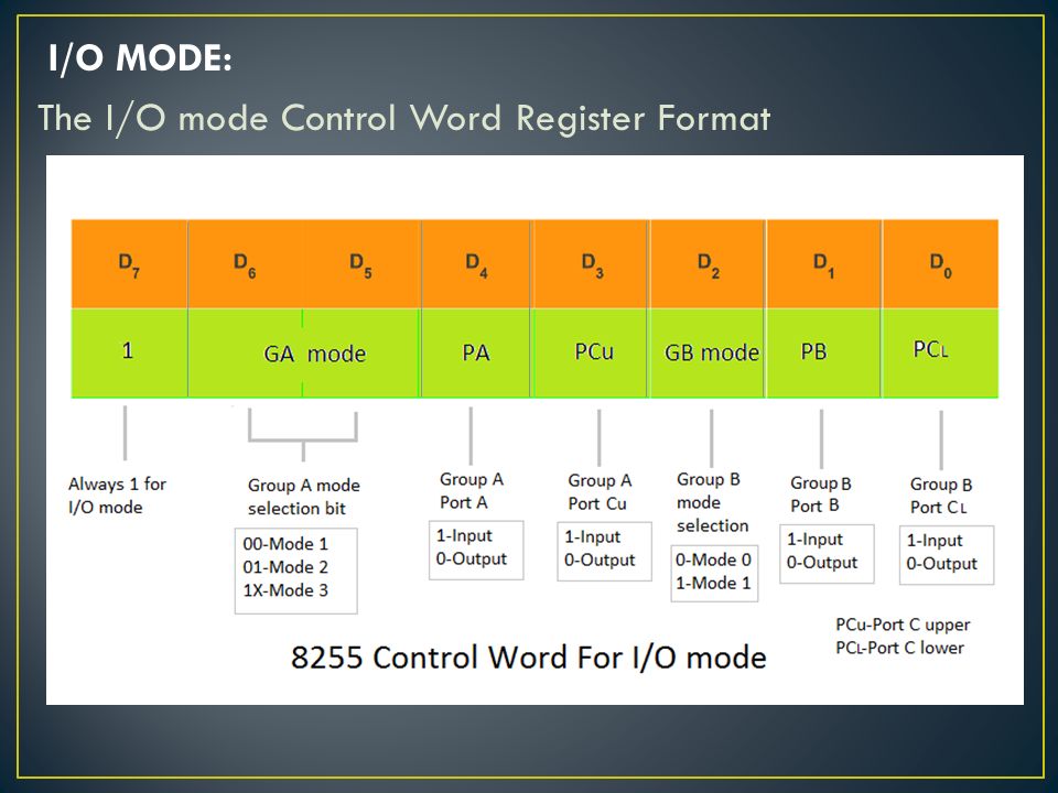
I/O MODE: The I/O mode Control Word Register Format

18
MODE 0(Simple input / Output): In this mode, port A, port B and port C is used as individually (Simply). Features: Outputs are latched, Inputs are buffered not latched. Ports do not have Handshake or interrupt capability.

19
MODE 1 :(Input/output with Hand shake) In this mode, input or output is transferred by hand shaking Signals. Port c signal lines Port B= port c(pc0-pc2) Port A= port c(pc3-pc5) Pc6,pc7 independent datalined Handshaking signals is used to transfer data between whose data transfer is not same.
 Port A= port c(pc3-pc5) Pc6,pc7 independent datalined Handshaking signals is used to transfer data between whose data transfer is not same..")
20
Input control signal definitions STB (Strobe input):If this line falls to logic low level, the data available at 8-bit input port is loaded into input latch. IBF(Input buffer full):1 indicates that data has been loaded into the latches. INTR(Interrupt request):This active high output can be used to interrupt the CPU whenever an input device requests the service.
:1 indicates that data has been loaded into the latches. INTR(Interrupt request):This active high output can be used to interrupt the CPU whenever an input device requests the service..")
21
Output control signal definitions OBF(Output buffer full):logic low indicates that the CPU has written data to the specified output port. ACK(Acknowledge input):logic low informs the CPU that the data transferred by the CPU to the output device through the port is received by the output device. INTR(Interrupt request):This is an output signal that can be used to interrupt the CPU when an output device acknowledges the data received from CPU.
:logic low informs the CPU that the data transferred by the CPU to the output device through the port is received by the output device. INTR(Interrupt request):This is an output signal that can be used to interrupt the CPU when an output device acknowledges the data received from CPU..")
22
MODE 2:bi-directional I/O data transfer: This mode allows bidirectional data transfer over a single 8-bit data bus using handshake signals. This feature is possible only Group A Port A is working as 8-biy bidirectional. PC 3 -PC 7 is used for handshaking purpose. The data is sent by CPU through this port, when the peripheral request it.

23
STB(Strobe input):low on this line is used to strobe in the data into the input latches of 8255. IBF(Input buffer full):logic high acknowledgement that the data has been received by the receiver.
:logic high acknowledgement that the data has been received by the receiver..")
24
Control signals for output operations OBF(Output buffer full):Logic low indicate that CPU has written data to port A. ACK(Acknowledge):Logic low level acknowledges that the previous data byte received by the destination and the next byte may be sent by the processor. INTE1(A flag associated with OBF):This can be controlled by bit set/reset mode with PC6.
:Logic low level acknowledges that the previous data byte received by the destination and the next byte may be sent by the processor. INTE1(A flag associated with OBF):This can be controlled by bit set/reset mode with PC6..")
Similar presentations


 access to programmable input/ output devices. It has three.>")


 Prepared by: Mahmoud Abdullah Mahdi 20060243 (33)>")


 Read-Write Memory (RAM)>")