Download presentation
Presentation is loading. Please wait.

1
8086

2
The 8086 is Intel’s first 16-bit microprocessor The 8086 can run at different clock speeds Standard 8086 – 5 MHz 8086-1 –10 MHz 8086-2 – 8 MHz The 8086 has a 20-bit address Can address upto 1 megabyte of memory The 8086 uses segmented memory Prefetches upto 6 instruction bytes from memory To speed up instruction execution

3
Larger memory size can be accessed The internal registers are 16 bit wide. They can address at most 64 Kbytes at most. The segment+offset approach produces a 20-bit address to access 1 Mbyte. Multi-tasking Each program occupies a particular code segment in memory. Multiple programs can be stored in different segments. They can be executed on the same processor. To switch from one to another, only the content of the segment register needs to be changed.

4
The memory of 8086-based microcomputer is organized as bytes. The 8086 always access a 16-bit word to or from memory. 8086 can be configured as a small uniprocessor system or as a multiprocessor system Using MN/MX pin HIGH –uniprocessor LOW-multiprocessor

5
The 8086 family consist of two type of 16 bit microprocessor – the 8086 and 8088. The 8086 has a 16-bit external data path to memory and I/O but the 8088 has a 8- bit external data path. In most other respects, the processors are identical.

7
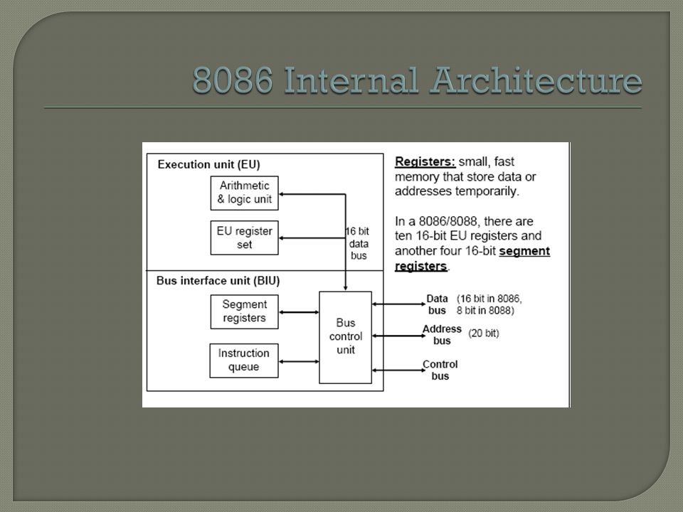
8086 is internally divided into two separate functional units Bus Interface Unit (BIU) Fetch Instruction Read/write data from/to memory or I/O ports Execution Unit (EU) Execute already fetched instruction
 Fetch Instruction Read/write data from/to memory or I/O ports Execution Unit (EU) Execute already fetched instruction")
13
Segments can be contiguous, partially overlapped, fully overlapped or disjoint

19
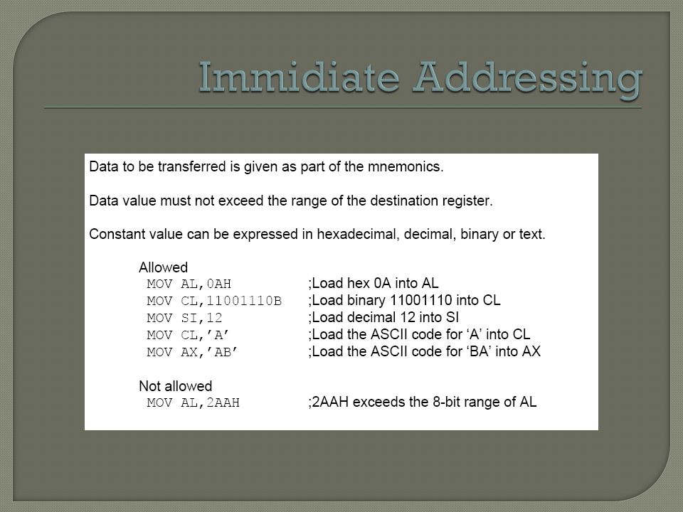
Consider the most commonly used instruction, MOV destination, source which attempts to transfer data “from source to destination”. source is either the data itself the name of a register, or specifying the address where the data is stored destination is either the name of a register, or specifying the address where the data is to be stored Addressing modes refer to how the locations of operands are specified.

29
Instructions using this mode specify the operand as a signed 8-bit displacement relative to PC. JNC START If carry = 0, then PC is loaded with current PC contents plus 8-bit signed value of START; otherwise, the next instruction is executed;

30
Instructions using this mode have no operands. CLC clears the carry flag to zero

32
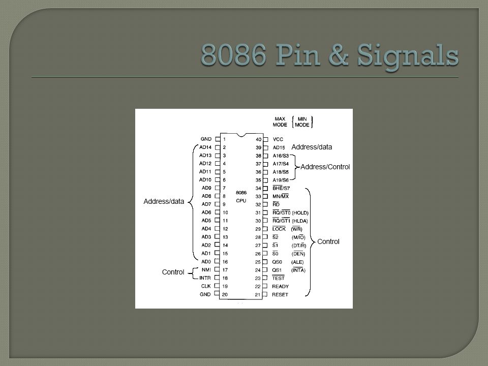
40 pins 16-bit bi-directional data bus. 20-bit output address bus Other pins are for control and status signals, and communication with peripherals Two operation modes: minimum mode & maximum mode Pins 24 through 31 and pin 34 perform different functions in minimum mode and maximum mode

33
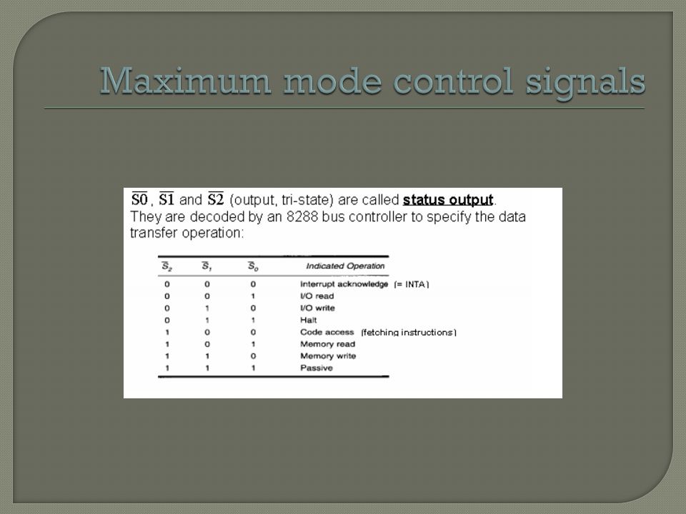
Minimum mode: 8086 generates all control signals by itself. There are 9 pins transmitting control signals: All are output signals except for HOLD. INTA, ALE, DEN, DT/R, M / IO, WR, HLDA, HOLD, SS0 Maximum mode: 8088 doesn’t generate control signals itself. Supporting chips are used to generate them. The 9 control- signal pins are saved for other purposes and the power of the processor will be maximally utilized.

34
Vcc and GND (input) provide the power supply. Vcc = 5 volts and GND = 0 CLK (input) receives the clock signal, which provides a reference for synchronization.
 receives the clock signal, which provides a reference for synchronization..")
35
AD0 – AD19 (bi- directional) transmit part of the address or 16-bit data. A16/S3 – A19/S6 (output) carry the most significant 4 bits of the address or 4 status bits. S3 and S4 indicate the segment register being used.
 carry the most significant 4 bits of the address or 4 status bits. S3 and S4 indicate the segment register being used..")
36
S5 indicates the Interrupt enable flag. Low in the S6 indicates 8086 is on the bus, during hold acknowledge period the 8086 tri-states the pin and allows another bus master to take control of the system bus

37
Remember that address pins are output ! A latch is like a “buffer” or “bridge” between the CPU address pins and the system address bus. The “bridge” allows one-way traffic, which is controlled by a latch enable signal. ALE pin from 8088 is used as the latch enable. 1) When the latch enable is low, the input pins are set at high- impedance state (don’t care) 2) When the enable line becomes high, the output is made equal to the input 3) If the enable line goes back low again, the output retains its current value.
 When the latch enable is low, the input pins are set at high- impedance state (don’t care) 2) When the enable line becomes high, the output is made equal to the input 3) If the enable line goes back low again, the output retains its current value..")
39
Signal on a tri-state pin may be in one of the three states: 1) low (0); 2) high (1); 3) open (high impedance) The “high-impedance” state is equivalent to disconnecting the pin from both the high and low voltage sources. If a pin is in the high-impedance state, it will not affect the system bus to which it is connected. Thus the bus can transmit other signals without being affected.

40
BHE (output): bus high enable, can be used to select memory banks RD (output):low when reading data from memory or an I/O location. TEST (input): used with WAIT instruction. INTR (input): maskable interrupt input, must be held at high level until recognized to generate an interrupt. NMI (input): nonmaskable interrupt input activated by a leading edge RESET (input): system reset signal
: used with WAIT instruction. INTR (input): maskable interrupt input, must be held at high level until recognized to generate an interrupt. NMI (input): nonmaskable interrupt input activated by a leading edge RESET (input): system reset signal.")
41
INTA (tri-state): interrupt acknowledge. ALE (output):address latch enable, indicating that the address is available on the bus. DEN (tri-state): data bus enable, indicating that the processor is ready to send or receive data. DT/R (tri-state): data transmit/receive, indicating whether the processor is sending or receiving data.
:address latch enable, indicating that the address is available on the bus. DEN (tri-state): data bus enable, indicating that the processor is ready to send or receive data. DT/R (tri-state): data transmit/receive, indicating whether the processor is sending or receiving data..")
42
IO/M (tri-state): accessing memory or I/O ? WR (tri-state): is the CPU outputting data ? HLDA (output):hold acknowledge HOLD (input): hold request from external circuitry
:hold acknowledge HOLD (input): hold request from external circuitry.")
43
LOCK (output): lock peripherals off the system RQ/GT1, RQ/GT0 (bi-directional): request/grant for the direct memory access (DMA) operation.
: lock peripherals off the system RQ/GT1, RQ/GT0 (bi-directional): request/grant for the direct memory access (DMA) operation.")
Similar presentations


 An Introduction to the 80x86 Microprocessor Family Objectives: The different addressing modes and instruction types available The usefulness.>")
![8086 [2] Ahad. Internal! External? 8086 vs 8088 16_bit Data Bus 20_bit Address 8_bit Data Bus 20_bit Address 8088 8086 Only external bus of 8088 is.](/11/3255261/big_thumb.jpg "8086 [2] Ahad. Internal! External? 8086 vs 8088 16_bit Data Bus 20_bit Address 8_bit Data Bus 20_bit Address 8088 8086 Only external bus of 8088 is.>")


