Download presentation
Presentation is loading. Please wait.

1
Dr. Kimberly E. Newman Hybrid Embedded wk3 Fall 2009

2
Necessary Stuff Lecture Notes are now on the course website Homework #1 due date extended to Thursday. Zip and email the files to me (newmanke@colorado.edu) while we work out the kinks in the CULEARN system.newmanke@colorado.edu Lab #3 – Interrupts and intro to debug

3
Polling vs. Interrupt Driven Interfacing

4
Expanding the I/O System Interrupt system: Allow devices to get processor’s attention Processor Memory - I/O Bus Main Memory I/O Controller Disk I/O Controller I/O Controller Graphics Network interrupts

5
Push Buttons

6
Interrupt Terms Hardware interrupt – an exception caused by a signal from hardware (request for action) IRQ- “Interrupt ReQuest” ISR- Interrupt Service Routine Code executed on the main processor in service of the device Interrupt vector - commonly referred to term for memory location holding the address of the interrupt service routine (ISR) Interrupt mask – used to block interrupts exception—Any condition or signal that interrupts normal program execution. Software: divide by 0, illegal opcode, etc.

7
Difference between Interrupts and Software Exceptions Interrupt is a hardware- based event Software exceptions originate from the program currently running on processor Handled in a similar way to interrupts: each designed cause will change the program to an “exception handler” routine.

8
NIOS II Interrupt Many devices Interrupt controller is generated by SOPC builder Controlled by IRQ number assignment 32 interrupt request lines Priority encoded IRQ[0] is highest priority
![NIOS II Interrupt Many devices Interrupt controller is generated by SOPC builder Controlled by IRQ number assignment 32 interrupt request lines Priority encoded IRQ[0] is highest priority](http://images.slideplayer.com/17/5337344/slides/slide_8.jpg "NIOS II Interrupt Many devices Interrupt controller is generated by SOPC builder Controlled by IRQ number assignment 32 interrupt request lines Priority encoded IRQ[0] is highest priority")
9
NIOS II Interrupt Controller

10
NIOS II Interrupt Controller 2

11
Exception Handling in Nios II When an interrupt occurs saves the status register disables hardware interrupts preserves the program counter or effective address register on the stack transfers control to the handler

12
Hardware Abstraction Layer (HAL) Lightweight runtime environment provides simple device driver interface allows access to devices with common C library functions
 Lightweight runtime environment provides simple device driver interface allows access to devices with common C library functions")
13
HAL Services Integration with C standard library Device drivers HAL API System initialization Device initialization

14
Interfacing with HAL Application developers using HAL API or C standard library do not consider the underlying hardware Device driver developers making drivers for low-level hardware interface newly written drivers with HAL

15
Generic Devices in HAL Character-mode devices Timer devices File subsystems Ethernet devices DMA devices Flash memory devices

16
Exception Handling in HAL Top level exception handler creates private stack stores register values onto the stack determines the type of exception and invoke the right SW or HW handler Software exception handler Hardware interrupt handler ISRs for peripherals

17
NIOS II Interrupt or Exception Control Diagram 1. Save the status registers 2. Disable interrupts 3. Save the EA (effective address register)…where the program was executing before interrupt Transfer control to the interrupt vector EA is also known as PC (Program Counter)
…where the program was executing before interrupt Transfer control to the interrupt vector EA is also known as PC (Program Counter).")
18
Exception Handling in HAL Check estatus to see if hardware interrupt is enabled if yes, check to see if the interrupt is hardware by checking ipending if yes, corresponding ISR is called if no, call the software exception handler Hardware interrupts have higher priority than software exceptions

19
Exception Handling in HAL Upon returning from exceptions, the top-level handler restores the stack pointer restores the registers from the stack exits by issuing an eret instruction

20
Exception Handling in HAL HW Handlers 32 hardware interrupts (0 to 31, with 0 as highest priority) priority is HAL specific and not NIOS II
 priority is HAL specific and not NIOS II")
21
Exception Handling in HAL SW handlers used for unimplemented instructions e.g. running multiplication on NIOS II with no multipliers traps

22
Interrupt Diagram Steps Advantage: User program progress is only halted during actual transfer Disadvantage, special hardware is needed to: Cause an interrupt (I/O device) Detect an interrupt (processor) Save the proper states to resume after the interrupt (processor) add sub and or nop read store... rti memory user program (1) I/O interrupt (2) save EA (3) Get interrupt service addr and change NIOS EA to that address interrupt service routine (4) CPU IOC device Memory :
 I/O interrupt (2) save EA (3) Get interrupt service addr and change NIOS EA to that address interrupt service routine (4) CPU IOC device Memory :.")
23
Get Interrupt Service Address (3) Get interrupt service addr and change NIOS EA to that address For each IRQ #, there is a memory address story in an interrupt vector table (also in memory). Upon that hardware selecting which IRQ, a LOAD to the corresponding vector table entry is performed. The result of that loaded value (4 bytes) is placed in the EA (effective address) of the NIOS Processor Thus the next instruction executed is the code for the Interrupt Service Routine (ISR)
 is placed in the EA (effective address) of the NIOS Processor Thus the next instruction executed is the code for the Interrupt Service Routine (ISR).")
28
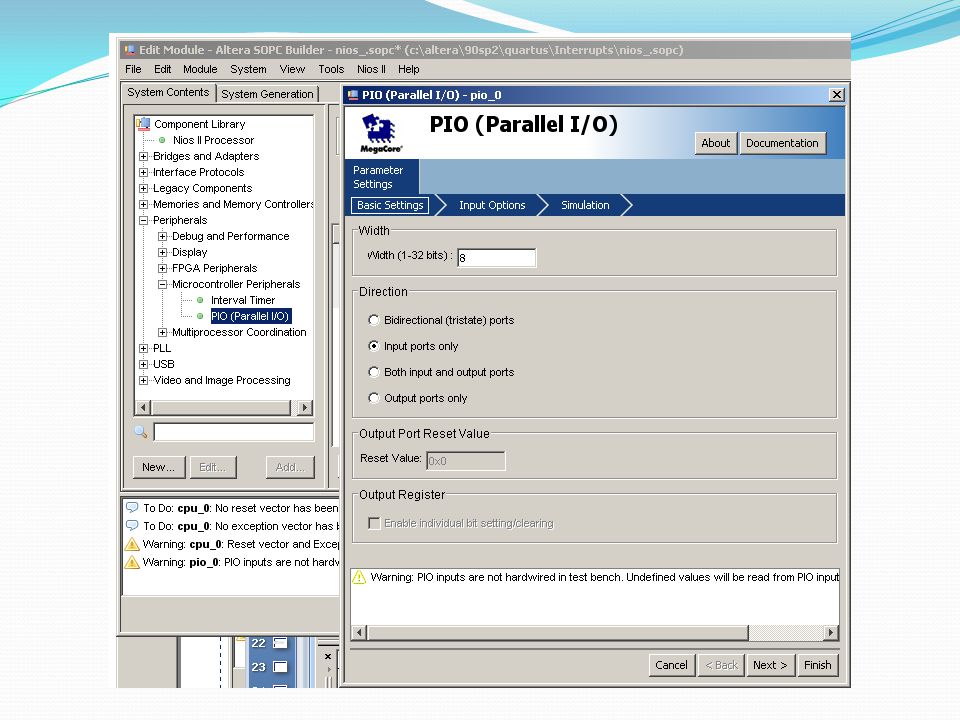
PIO Core Types: Output, Input w/ Interrupt, Bi-directional

29
PIO Device Map Base address assigned from SOPC But device is 4 register locations (4 bytes each location) Registers are: DATA, Direction, InterruptMask, Edgecapture
 Registers are: DATA, Direction, InterruptMask, Edgecapture")
30
PIO CORE Data

31
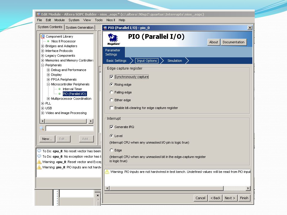
PIO CORE Edgecapture

32
PIO CORE Interrupt (IRQ) Generation
 Generation")
33
PIO CORE Configurations

34
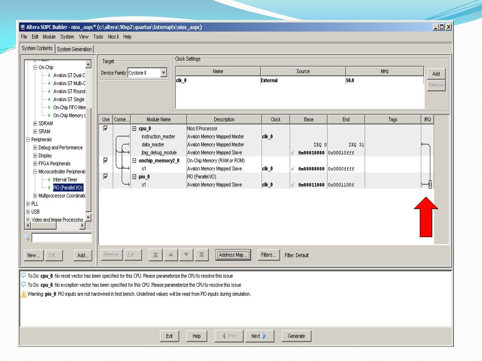
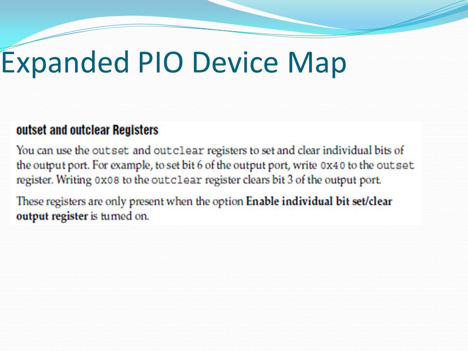
Expanded PIO Device Map

38
Hardware Abstraction Layer (HAL). –System software that allows programmer to control the hardware devices using a series of function calls –Control how or whether interrupts should be handled –i.e. turn off interrupts when code executing on NIOS II CPU is critical (time constraint), don’t allow serial input cable to get processor’s attention
, don’t allow serial input cable to get processor’s attention.")
39
HAL Interface

40
NIOS II Interrupt Setup Declare variable for holding information that will be passed from device to ISR Enable the device Set the control registers on the device Register the ISR with the HAL system Done in main() Develop code for ISR
 Develop code for ISR")
41
Enable Device and Register ISR Register the ISR with the HAL interface: assign address of the ISR to the Interrupt vector table. Set the controls on the PIO device to capture and cause interrupts Declare variable to hold state of device that will be passed to ISR

42
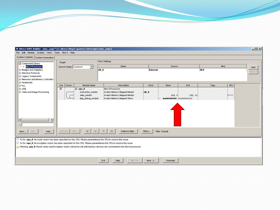
Enable Device and Register ISR This is decided at SOPC builder time, user can define which IRQ # [0 up to 31] Memory- mapped device address assigned at SOPC builder time
![Enable Device and Register ISR This is decided at SOPC builder time, user can define which IRQ # [0 up to 31] Memory- mapped device address assigned at SOPC builder time](http://images.slideplayer.com/17/5337344/slides/slide_42.jpg "Enable Device and Register ISR This is decided at SOPC builder time, user can define which IRQ # [0 up to 31] Memory- mapped device address assigned at SOPC builder time")
43
NIOS II Interrupt Example ISR #include “system.h” #include “altera_avalon_pio_regs.h” #include “alt_types.h” static void handle_button_interrupts(void* context, alt_u32 id) { // cast the context pointer to an integer pointer. volatile int* edge_capture_ptr = (volatile int*) context; //Read the edge capture register on the button PIO & Store value. *edge_capture_ptr= IORD_ALTERA_AVALON_PIO_EDGE_CAP(BUTTONS_BASE); //Write to the edge capture register to reset it. IOWR_ALTERA_AVALON_PIO_EDGE_CAP(BUTTONS_BASE, 0); // reset interrupt capability for the Button PIO. IOWR_ALTERA_AVALON_PIO_IRQ_MASK(BUTTONS_BASE, 0xf); }
 context; //Read the edge capture register on the button PIO & Store value. *edge_capture_ptr= IORD_ALTERA_AVALON_PIO_EDGE_CAP(BUTTONS_BASE); //Write to the edge capture register to reset it. IOWR_ALTERA_AVALON_PIO_EDGE_CAP(BUTTONS_BASE, 0); // reset interrupt capability for the Button PIO. IOWR_ALTERA_AVALON_PIO_IRQ_MASK(BUTTONS_BASE, 0xf); }.")
44
NIOS II Interrupt Example ISR-Expanded static void handle_button_interrupts(void* context, alt_u32 id) { // cast the context pointer to an integer pointer. volatile int* edge_capture_ptr = (volatile int*) context; //Read the edge capture register on the button PIO & Store value. *edge_capture_ptr= IORD_ALTERA_AVALON_PIO_EDGE_CAP(BUTTONS_BASE); //Write to the edge capture register to reset it. IOWR_ALTERA_AVALON_PIO_EDGE_CAP(BUTTONS_BASE, 0); // reset interrupt capability for the Button PIO. IOWR_ALTERA_AVALON_PIO_IRQ_MASK(BUTTONS_BASE, 0xf); if ( *edge_capture_ptr == 1) // Check if the first button was pressed LCDwrite("hello world\n"); if ( *edge_capture_ptr == 4) // Check if the 4 th button was pressed { IOWR(LEDS_BASE,0, (1 & 0xF)); // Write 1 to the LEDs usleep(1000000); IOWR(LEDS_BASE,0, (0 & 0xF)); // Write 0 to the LEDs }
 context; //Read the edge capture register on the button PIO & Store value. *edge_capture_ptr= IORD_ALTERA_AVALON_PIO_EDGE_CAP(BUTTONS_BASE); //Write to the edge capture register to reset it. IOWR_ALTERA_AVALON_PIO_EDGE_CAP(BUTTONS_BASE, 0); // reset interrupt capability for the Button PIO. IOWR_ALTERA_AVALON_PIO_IRQ_MASK(BUTTONS_BASE, 0xf); if ( *edge_capture_ptr == 1) // Check if the first button was pressed LCDwrite( hello world\n ); if ( *edge_capture_ptr == 4) // Check if the 4 th button was pressed { IOWR(LEDS_BASE,0, (1 & 0xF)); // Write 1 to the LEDs usleep( ); IOWR(LEDS_BASE,0, (0 & 0xF)); // Write 0 to the LEDs }.")
45
NIOS II Interrupt Handling Performance

Similar presentations