Download presentation
Presentation is loading. Please wait.

1
Internal Model Control for DC Motor Using DSP Platform By: Marcus Fair Advisor: Dr. Dempsey

2
Outline Problem description Objectives Functional Specs Sub-system Overview Software Design

3
Summary Design, build, and test IMC (Internal Model Control) system to control a DC motor 32-bit TMS320F2812 digital signal processor (DSP) Design for IMC controller built in Simulink Input to system uses graphical user interface (GUI) built in Matlab
 system to control a DC motor 32-bit TMS320F2812 digital signal processor (DSP) Design for IMC controller built in Simulink Input to system uses graphical user interface (GUI) built in Matlab")
4
Preliminary Work DC Motor block diagrams from Senior Mini- project Also based on DC Motor Speed Control Demo M-files to run software Speed Measurement block in Simulink

5
Common Problems in Control Systems Load Changes -Load shaft Plant Changes -Armature Resistor, Armature Inductor, Rotor Inertia, etc Power Supply Changes

6
Objectives Build DSP/motor hardware interface Design and build (GUI) Design closed-loop controllers Compare conventional controller results with the IMC method
 Design closed-loop controllers Compare conventional controller results with the IMC method")
7
Functional Requirements and Performance Specifications Closed-loop operation: Determine optimum gains for controllers Rise time: 20 ms or less Settling time: 100ms or less Overshoot: < or = 5% Steady state error: + or – 5 RPM

8
Equipment List GM9236C534-R2 Pittman DC motor Ezdsp F2812 Board LMD18200 H-bridge 3 - SN74LVC4245A voltage shifter 6-Pin DIP Opto-isolator 2N2222A BJT 2 - Diodes Agilent 30V power supply and HP 5V power supply Tektronix Oscilloscope

9
Overall Block Diagram

11
Dsp board technical specs GenerationTMS320F281x CPU1 C28x Peak MMACS150 Frequency(MHz)150 RAM36 KB OTP ROM2 KB Flash256 KB EMIF1 16-Bit PWM16-Ch CAP/QEP6/2 ADC1 16-Ch 12-Bit ADC Conversion Time80 ns McBSP1 UART2 SCI SPI 1 CAN1 Timers3 32-Bit GP,1 WD GPIO56 Core Supply (Volts)1.9 V IO Supply (Volts)3.3 V
150 RAM36 KB OTP ROM2 KB Flash256 KB EMIF1 16-Bit PWM16-Ch CAP/QEP6/2 ADC1 16-Ch 12-Bit ADC Conversion Time80 ns McBSP1 UART2 SCI SPI 1 CAN1 Timers3 32-Bit GP,1 WD GPIO56 Core Supply (Volts)1.9 V IO Supply (Volts)3.3 V")
12
Inputs and Outputs

13
H-bridge Delivers up to 3A continuous output Operates at supply voltages up to 55V Low RDS(ON) typically 0.3W per switch TTL and CMOS compatible inputs No “shoot-through” current Thermal warning flag output at 145°C Thermal shutdown (outputs off) at 170°C Internal clamp diodes Shorted load protection Internal charge pump with external bootstrap capability Internal clamp diodes Shorter load protection Internal charge pump with external bootstrap capability
 typically 0.3W per switch TTL and CMOS compatible inputs No shoot-through current Thermal warning flag output at 145°C Thermal shutdown (outputs off) at 170°C Internal clamp diodes Shorted load protection Internal charge pump with external bootstrap capability Internal clamp diodes Shorter load protection Internal charge pump with external bootstrap capability")
14
Pittman DC Motor Motor Specs Encoder Specs

15
Pittman Motor Block Diagram

16
Root Locus of Plant

17
Bode Plot for Plant

18
Software Matlab - Simulink -main m-files -Gui m-files Code Composer Studio 2.0 -Auto-code generation -Communication with Dsp board

19
Software flowchart

21
Design Work Matlab GUI -Gui m-file Controller Design Iterations -Proportional Controller -Feed-forward Controller -IMC controller

22
GUI

23
Proportional Controller

25
Other Block diagrams

26
Proportional Controller

27
Proportional Controller Simulink Results

28
Proportional Controller Actual Results

30
Feed-forward Controller Why Feed-forward Controller? Faster response to command changes than single-loop controllers Less overshoot: More accurate than single-loop controllers Better system for Dc Motor control

31
Feed-forward Controller

32
Feed-forward Equations C/R = (Gc*Gp + Gp) / (1 + Gp) Desired C/R = 1.0 So Gc = 1/Gp to get desired controller Gain K calculated based on DC gain of plant
 / (1 + Gp) Desired C/R = 1.0 So Gc = 1/Gp to get desired controller Gain K calculated based on DC gain of plant")
33
Feed-forward Controller

35
Feed-forward Controller Simulink Results

36
Feed-forward Controller Actual Results

38
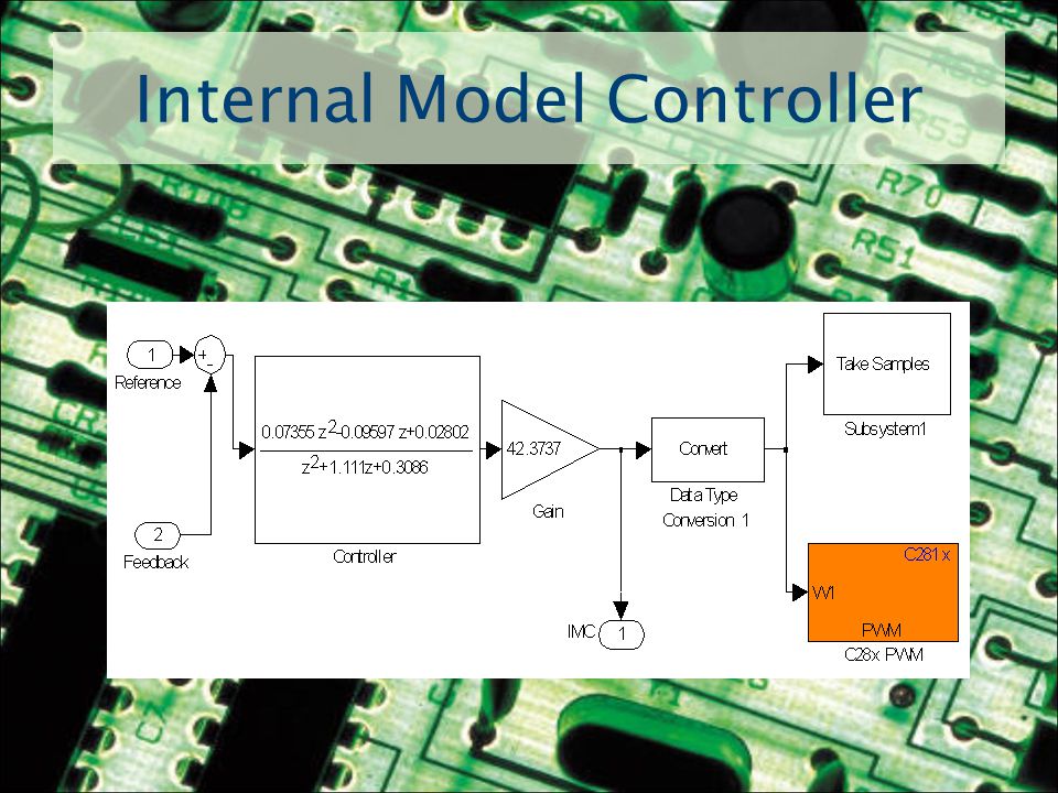
Internal Model Controller IMC uses a plant model for disturbance rejection More ideal control system Faster and more robust system

39
Internal Model Controller

40
IMC Equations C/R = (Gc*Gp)/(1 + Gc*Gp - Gc*Gp’) Desired C/R = 1.0 So Gc = 1/Gp’ = 1/Gp to get desired controller Gain K calculated based on DC gain of plant
/(1 + Gc*Gp - Gc*Gp’) Desired C/R = 1.0 So Gc = 1/Gp’ = 1/Gp to get desired controller Gain K calculated based on DC gain of plant")
41
Internal Model Controller

43
Internal Model Controller Simulink Results

44
IMC Controller Actual Results Hardware didn’t support algebraic loops Unable to Run IMC from processor

45
Conclusion Overall Hardware fully functional Functional parts of GUI work correctly/ extra features never implemented All Controllers work in Simulation Only proportional and feed-forward run off hardware

46
Questions?

47
Feed-Forward Equations C = Gp*(R*Gc + E) E = R - C C = Gc*Gp*R + Gp*R – C*Gp C + C*Gp = Gc*Gp*R + Gp*R C = R*(Gc*Gp + GP) / (1 + GP) C/R = (Gc*Gp + Gp) / (1 + Gp)
 E = R - C C = Gc*Gp*R + Gp*R – C*Gp C + C*Gp = Gc*Gp*R + Gp*R C = R*(Gc*Gp + GP) / (1 + GP) C/R = (Gc*Gp + Gp) / (1 + Gp)")
48
IMC EQUATIONS C = E*Gc*Gp E = R – (E*Gc*Gp – E*Gc*Gp’) E + E*Gc*Gp - E*Gc*Gp’ = R E = R / (1 + Gc*Gp - Gc*Gp’) C = (R*Gc*Gp) / (1 + Gc*Gp - Gc*Gp’) C/R = (Gc*Gp) / (1 + Gc*Gp - Gc*Gp’)
 E + E*Gc*Gp - E*Gc*Gp’ = R E = R / (1 + Gc*Gp - Gc*Gp’) C = (R*Gc*Gp) / (1 + Gc*Gp - Gc*Gp’) C/R = (Gc*Gp) / (1 + Gc*Gp - Gc*Gp’)")
49
Spring Semester Schedule WeekGoals 1-7 Build and test single-loop controller, Design Gui layout 8 Build and test feed-forward controller 9-10 Implement IMC with linear model 11 Final testing, final Gui design 12-13 Final documentation

50
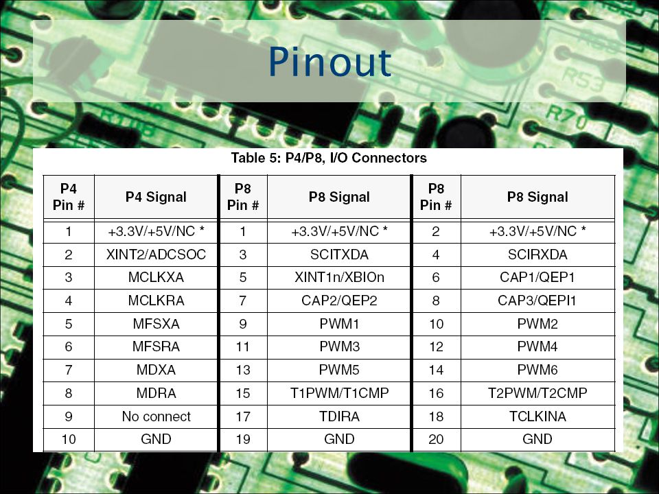
Pinout

Similar presentations


>")


 By: Adam Green Advisor: Dr. Aleksander Malinowski.>")


