Download presentation
Presentation is loading. Please wait.

1
Students: Andrew Fouts Kurtis Liggett Advisor: Dr. Dempsey

2
Presentation Overview Project Summary Observer-based control Equipment Project Goals System Block Diagram Functional Requirements Engine Subsystem Thermal Subsystem Results 2

3
Project Summary Engine cooling control workstation Several control methods Proportional control PI control Feedforward Optimum Phase Margin Observer-based control CAN bus communication 3

4
Observers in Controls Overview Advantages Reduced number of sensors Increase stability Disadvantages Added complexity Computational Resources Response to large plant changes George Ellis. “Observers in Control Systems”, Academic Press, 2002. 4

5
Equipment Pittman motors (2) Motor Heat Sinks H-bridge 30 volt, 315 watt switching power supply Control and interfacing circuitry eZdsp F2812 TI DSP boards(2) Fan Radiator Cooling block Reservoir and pump Flow meter Coolant Code Cathode Temperature Sensors (3) Tubing, clamps 5
 Motor Heat Sinks H-bridge 30 volt, 315 watt switching power supply Control and interfacing circuitry eZdsp F2812 TI DSP boards(2) Fan Radiator Cooling block Reservoir and pump Flow meter Coolant Code Cathode Temperature Sensors (3) Tubing, clamps 5")
6
Project Workstation 6 Nick Schmidt

7
Power Electronics 7 Dr. Dempsey

8
Project Goals Learn software packages Design several types of controllers & evaluate performance of each Develop energy management control system in Simulink environment to regulate voltage/current to each subsystem Determine the limitations of the Simulink/DSP interface 8

9
System Block Diagram 9

10
Functional Requirements Engine control system: Steady-state error = ± 5 RPM Percent overshoot ≤ 10% Rise time ≤ 30 ms Settling time ≤ 100 ms Phase margin = 45° Thermal control system: Steady-state error = ±2° Celsius Percent overshoot ≤ 25% Rise time ≤ 2 seconds Settling time ≤ 10 seconds Phase margin = 45° 10

11
Engine Subsystem

12
Developing Engine Models Simulink Model Easy to Build Scope Outputs Control System Toolbox Model Frequency Domain Design Incorporate Time Delay Model Comparison

13
Engine Model Comparison Simulink Step Response Control System Toolbox Step Response

14
Lab Work - Engine PWM, Quadrature Encoder, and A/D Tutorials Mini-project implementation Proportional control PI control Feedforward control Observer-based control

15
Lab Work - Engine

16
1/Ra Observed Current

17
Lab Work – Engine (Simulink)
")
19
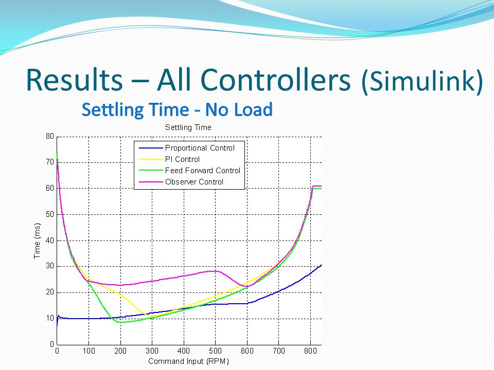
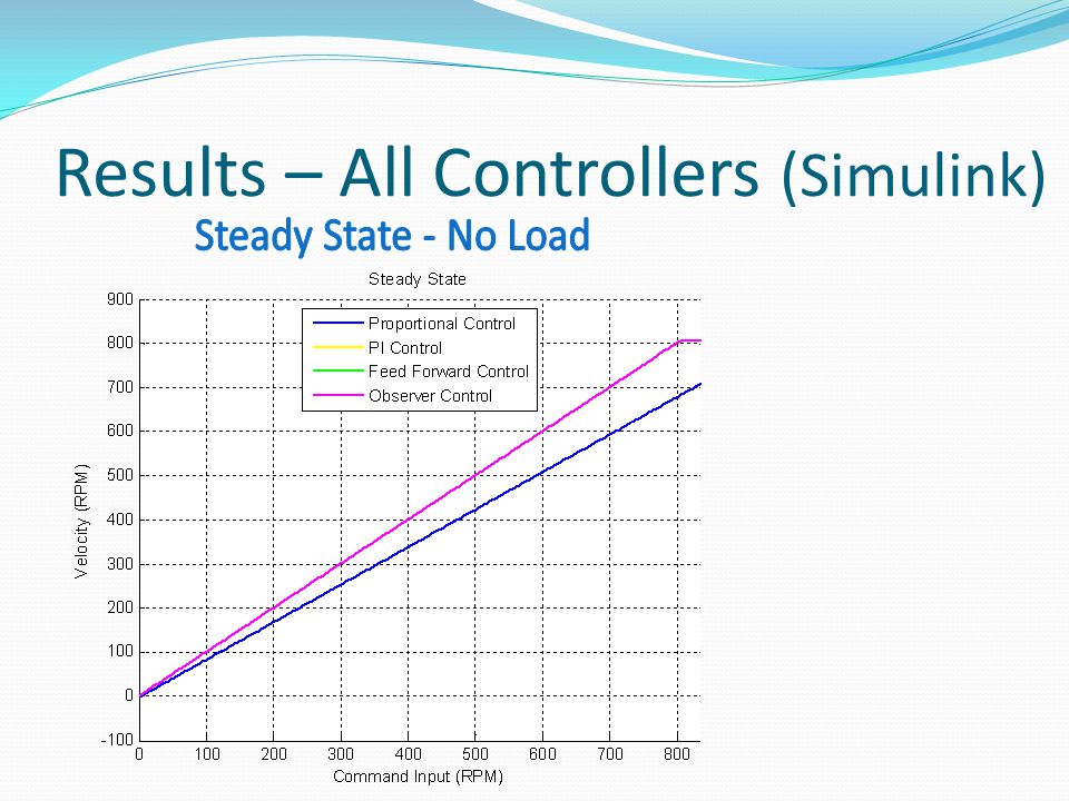
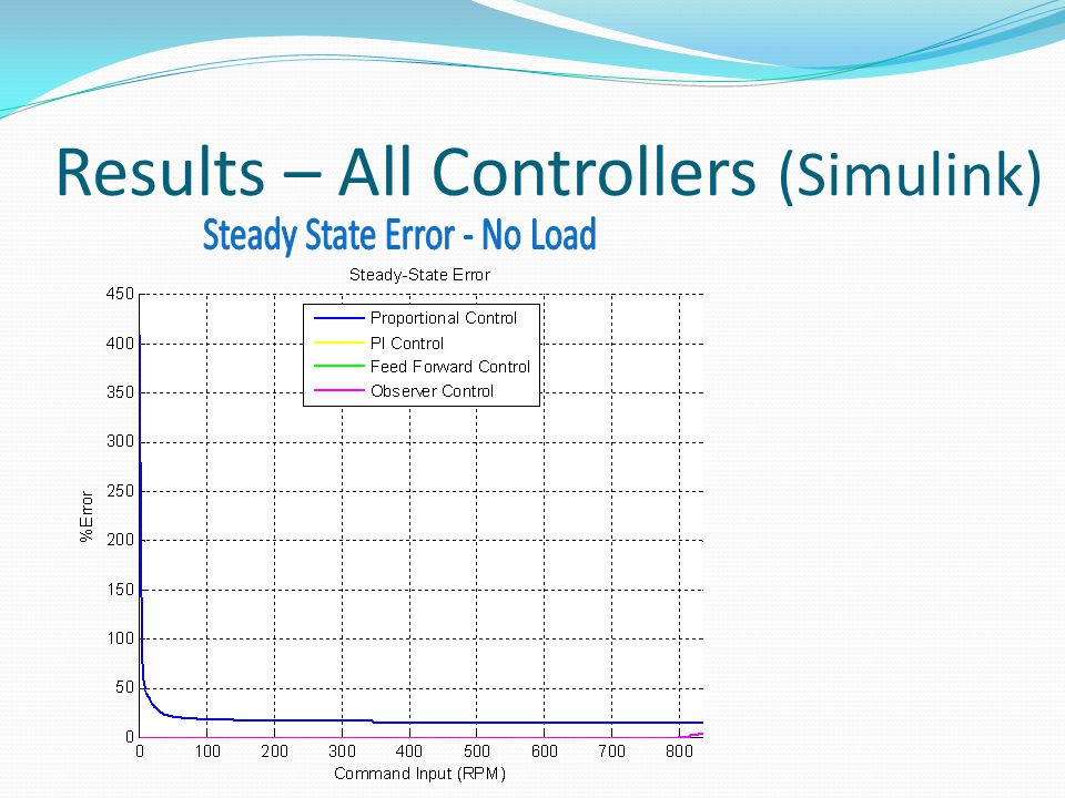
Results – All Controllers (Simulink)
")
23
Results – All Controllers ControllerAdvantagesDisadvantages ProportionalSimpleSteady-state error Very fast Small operating range Sensor cost PIZero steady-state errorLonger rise time Sensor cost Feed forwardZero steady-state errorMore complex Sensor cost ObserverZero steady-state errorGreatest computational resources Reduced sensor cost Observable states

24
Thermal Subsystem

25
Lab Work - Thermal Thermistor-temperature calculation Proportional controller design System identification & proportional-integral controller design Optimum-phase margin/frequency controller design Anti-windup design Observer-based controller design 25

26
Lab Work - Thermal

27
Optimum phase margin – Bode diagram

28
Lab Work - Thermal Anti-windup design 28

29
Lab Work - Thermal 29

30
Results – Thermal (models) PI Model RiseTime: 6.07 s SettlingTime: 38.52 s Overshoot: 19.23% PeakTime: 15.72 s OPM Model RiseTime: 4.14 s SettlingTime: 43.96 s Overshoot: 56.75% PeakTime: 13 s Observer Model RiseTime: 6.70 s SettlingTime: 44.44 s Overshoot: 8.82% PeakTime: 26.85 s
 PI Model RiseTime: 6.07 s SettlingTime: s Overshoot: 19.23% PeakTime: s OPM Model RiseTime: 4.14 s SettlingTime: s Overshoot: 56.75% PeakTime: 13 s Observer Model RiseTime: 6.70 s SettlingTime: s Overshoot: 8.82% PeakTime: s")
31
Results – All Controllers ControllerAdvantagesDisadvantages PIZero steady-state errorSlow speed Low complexity Moderate overshoot OPMZero steady-state errorModerate complexity Fast speed High overshoot ObserverZero steady-state error High complexity Low overshoot Slow speed

32
Overall Results Successfully implemented observer in engine subsystem Successfully implemented observer in cooling subsystem Planned Engine governor system Cooling system power conservation Intersystem CAN bus communication 32

33
Questions 33

34
Other Specs Thermal System sampling time 500 ms (-2.9 degrees @ Wc =.2 rad/sec) Thermal System time delay 1.7 sec (-20 degrees @ Wc =.2 rad/sec) Thermistor accuracy Average % error = 0.9% DSP board specifications 32-bit system 12-bit A/D converter 34
 Thermal System time delay 1.7 sec (-20 Wc =.2 rad/sec) Thermistor accuracy Average % error = 0.9% DSP board specifications 32-bit system 12-bit A/D converter 34")
35
Z-plane controllers Thermal OPM controller 35

36
Z-plane controllers Thermal OPM controller (zoomed in) 36
 36")
Similar presentations

 Universiti Putra Malaysia 11-12 August, 2004 Dr. Nik Rumzi Nik Idris Department.>")
/40GXC(Q) Service Training Sizes 18 and 24K.>")


 By: Adam Green Advisor: Dr. Aleksander Malinowski.>")


 763-5373>")

