Download presentation
Presentation is loading. Please wait.

1
Subject: M.E. 108 , 143 Fundamentals of Heat Exchanger Design Wednesday , July 27, 2011 Lecturer: Prof. Gennaro J. Maffia

2
ME-108 Principles of Heat Exchanger Design, Part I
This seminar provides an overview of the equipment used for the transfer of heat in the process industries, including that used in chemical plants, refineries, and cogeneration power plants. The transformation of the basic heat balance into a T-Q curve and the resulting zone analysis to produce an effective design is covered. Selection of the appropriate TEMA designation, as well as economic and environmental considerations will be addressed. The seminar will conclude with a discussion of the techniques, such as Pinch Technology, in developing a heat exchanger network. ME-143 Principles of Heat Exchanger Design, Part II This seminar provides a continuation of the discussion of the equipment used for the transfer of heat. Specific examples and case studies will highlight analysis techniques and step-wise procedures. Emphasis will be placed on the calculation of the film coefficient for a variety of different geometries and how to compose an overall heat transfer coefficient. Transfer line exchangers, plate-fin exchangers and Joule-Thompson exchangers are among the examples covered.

3
ME-108 Principles of Heat Exchanger Design, Part I
overview of the equipment used for the transfer of heat in the process industries, including that used in chemical plants, refineries, and cogeneration power plants. basic heat balance into a T-Q curve and the resulting zone analysis to produce an effective design TEMA designation, as well as economic and environmental considerations will be addressed. Pinch Technology

4
Fundamentals of Heat Exchanger Design This seminar provides an overview of the used for the transfer of heat in the process industries, including that used in chemical plants, refineries, and cogeneration power plants.

5
The transformation of the basic heat balance into a T-Q curve and the resulting zone analysis to produce an effective design is covered. Selection of the appropriate TEMA designation, as well as economic and environmental considerations will be addressed.

6
The seminar will conclude with a discussion of the techniques, such as Pinch Technology, in developing a heat exchanger network.

7
Dr. Gennaro Maffia, D.E., MBA
After twenty years of industrial experience with large multinational companies, Dr. Maffia served as the Chairman of the Chemical Engineering Department at Widener University until He is currently Prof. of Chem. Eng at Manhattan College, Prof Emeritus at Widener University and Adjunct Prof. of Chem. and Biol. Engr. at Drexel University. Prof. Maffia is a member of many professional and honor societies as well as being an associate of several consulting companies. His research interests include the development of environmental remediation and biomedical technologies bases on water retention properties of unraveled bovine hide collagen. He holds a doctorate from Dartmouth College and a MBA from NYU.

11
Founded in 1821, Widener University is a multi-campus, independent, metropolitan university. It offers a student-centered learning environment where course work connects to societal issues. Dynamic teaching, active scholarship, personal attention, and experiential learning are key components of the Widener experience. The university provides a unique combination of liberal arts and professional education through its eight schools and colleges.

12
Collagen Research Lineage
Started at Dartmouth ‘85 cell culture Verax - FBBR Widener Environmental Angle flocculation filtration fractionation Tailor Made Substrates Other Applications 1

13
Collagen Research Group Department of Chemical Engineering
Widener University Time Capsule 1985 – 1988 Dartmouth College - Initial Research 1985 – 1995 Verax Corp., Lebanon, NH 1994 – 2006 Collagen Research Group, Widener U 150+ students, professors, and colleagues have worked on protein research at Widener since 1994 HS summer interns and summer campers – 50-75 per year since 1996

14
Collagen Research Group Department of Chemical Engineering
Major Collagen Projects manufacture and applications of the main products collagen dispersions water treatment environmental remediation intermediate lyophilized collagen matrices controlled release lost protein technology sterile, crosslinked collagen matrices biotech/biomedical tissue engineering

15
Some Chemical Engineering Students and Professors
Donna Stauffer and Prof. Maffia Brian Coll, Megan Winkelman, and Prof. Maffia Jennifer Hubbell Freshman and Prof. Maffia Prof. McNeil, Charlene Emlet, Eric Shaw and Donna Stauffer Widener University Some Chemical Engineering Students and Professors contact: Audra Rizzetto Monica Beistline

16
C B T M A P C R G Biotechnology Miscellaneous
milling and dispersion (smart material) Biotechnology Cell Immobilization reactor design biosensing tissue engineering Biomolecule Delivery Controlled Release Miscellaneous Dispersing Agent Infrastructure Insulation Micro-encapsulation Coating of Medical Devices Additive for Photocatalyst Coating Lost Protein & Catalyst Manufacture Environmental Extraction Filtration Aid Flocculation and Settling C R G
 Biotechnology. Cell Immobilization. reactor design. biosensing. tissue engineering. Biomolecule Delivery. Controlled Release. Miscellaneous. Dispersing Agent. Infrastructure. Insulation. Micro-encapsulation. Coating of Medical Devices. Additive for Photocatalyst Coating. Lost Protein. & Catalyst Manufacture. Environmental. Extraction. Filtration Aid. Flocculation. and Settling. C. R. G.")
17
AFTER MILLING AND WASHING
nm diameter AFTER MILLING AND WASHING

19
6

21
not viable in most situations Indirect streams do not mix
Heat Transfer Direct stream mixing cheap not viable in most situations Indirect streams do not mix

22
Heat Transfer Mechanisms
Conduction Convection Radiation

23
Conduction is the transfer of thermal energy from a region of higher temperature to a region of lower temperature through direct molecular communication within a medium or between mediums in direct physical contact without a flow of the material medium. Metals (eg. copper) are usually the best conductors of thermal energy. Fluids (liquids (except liquid metals) and gasses) are not typically good conductors.
 are usually the best conductors of thermal energy. Fluids (liquids (except liquid metals) and gasses) are not typically good conductors..")
24
Convection is a combination of conduction and the transfer of thermal energy by fluid circulation or movement of the hot particles in bulk to cooler areas in a material medium. Unlike the case of pure conduction, now currents in fluids are additionally involved in convection. This movement occurs into a fluid or within a fluid, and cannot happen in solids. In solids, molecules keep their relative position to such an extent that bulk movement or flow is prohibited, and therefore convection does not occur.

25
Radiation is transfer of heat through electromagnetic radiation
Radiation is transfer of heat through electromagnetic radiation. Hot or cold, all objects radiate energy at a rate equal to their emissivity times the rate at which energy would radiate from them if they were a black body. No medium is necessary for radiation to occur; radiation works even in and through a perfect vacuum. Both reflectivity and emissivity of all bodies is wavelength dependent. The temperature determines the wavelength distribution of the electromagnetic radiation as limited in intensity by Plank’s law of black-body radiation.

26
Heat Transfer Mechanisms
Conduction Convection Radiation

27
Shell and tube heat exchanger
indirect heat transfer most common type of heat exchanger in oil refineries and other large chemical processes suited for higher-pressure applications

28
Shell and tube heat exchanger
consists of a shell (a large pressure vessel) with a bundle of tubes inside it. One fluid runs through the tubes, and another fluid flows over the tubes (through the shell) to transfer heat between the two fluids. The set of tubes is called a tube bundle, and may be composed by several types of tubes: plain, longitudinally finned, etc.
 with a bundle of tubes inside it. One fluid runs through the tubes, and another fluid flows over the tubes (through the shell) to transfer heat between the two fluids. The set of tubes is called a tube bundle, and may be composed by several types of tubes: plain, longitudinally finned, etc.")
29
Basics Two fluids, of different starting temperatures, flow through the heat exchanger. One flows through the tubes (the tube side) and the other flows outside the tubes but inside the shell (the shell side). Heat is transferred from one fluid to the other through the tube walls, either from tube side to shell side or vice versa. This process is best represented by a T-Q diagram
 and the other flows outside the tubes but inside the shell (the shell side). Heat is transferred from one fluid to the other through the tube walls, either from tube side to shell side or vice versa. This process is best represented by a T-Q diagram.")
30
Bottom Line At every point in the HX, the hot stream must be hotter than the cold stream by a distance called the driving force

44
Temperature Heat Transfer Rate or Duty

45
Temperature Heat Transfer Rate or Duty

46
Temperature Heat Transfer Rate or Duty

47
Temperature Heat Transfer Rate or Duty

48
Temperature Heat Transfer Rate or Duty

49
Temperature Heat Transfer Rate or Duty

50
Temperature Heat Transfer Rate or Duty

51
Temperature Heat Transfer Rate or Duty

52
Temperature Heat Transfer Rate or Duty

53
Temperature Heat Transfer Rate or Duty

54
The fluids can be either liquids or gases on either the shell or the tube side. In order to transfer heat efficiently, a large heat transfer area should be used, so there are many tubes. In this way, waste heat can be put to use. This is a great way to recuperate energy.

55
Heat exchangers with only one phase (liquid or gas) on each side can be called one-phase or single-phase heat exchangers. Two-phase heat exchangers can be used to heat a liquid to boil it into a gas (vapor), sometimes called boilers, or cool a vapor to condense it into a liquid (called condensers), with the phase change usually occurring on the shell side.
, sometimes called boilers, or cool a vapor to condense it into a liquid (called condensers), with the phase change usually occurring on the shell side..")
56
In large power plants with steam-driven turbines, shell-and-tube surface condensers are used to condense the exhaust steam exiting the turbine into condensate water which can be recycled back to be turned into steam, possibly into a shell-and-tube type boiler.

57
Shell and tube heat exchanger design
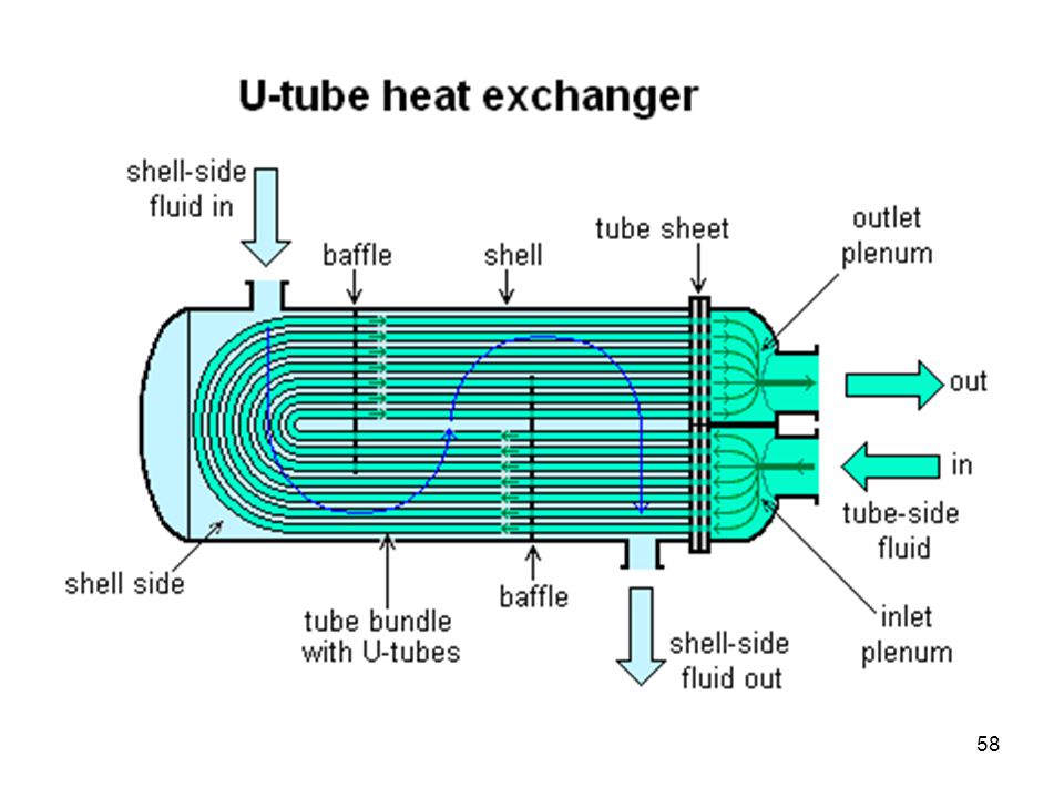
There can be many variations on the shell and tube design. Typically, the ends of each tube are connected to plenums (sometimes called water boxes) through holes in tubesheets. The tubes may be straight or bent in the shape of a U, called U-tubes.
 through holes in tubesheets. The tubes may be straight or bent in the shape of a U, called U-tubes.")
62
In nuclear power plants called pressurized water reactors, large heat exchangers called steam generators are two-phase, shell-and-tube heat exchangers which typically have U-tubes. They are used to boil water recycled from a surface condenser into steam to drive the turbine to produce power.

63
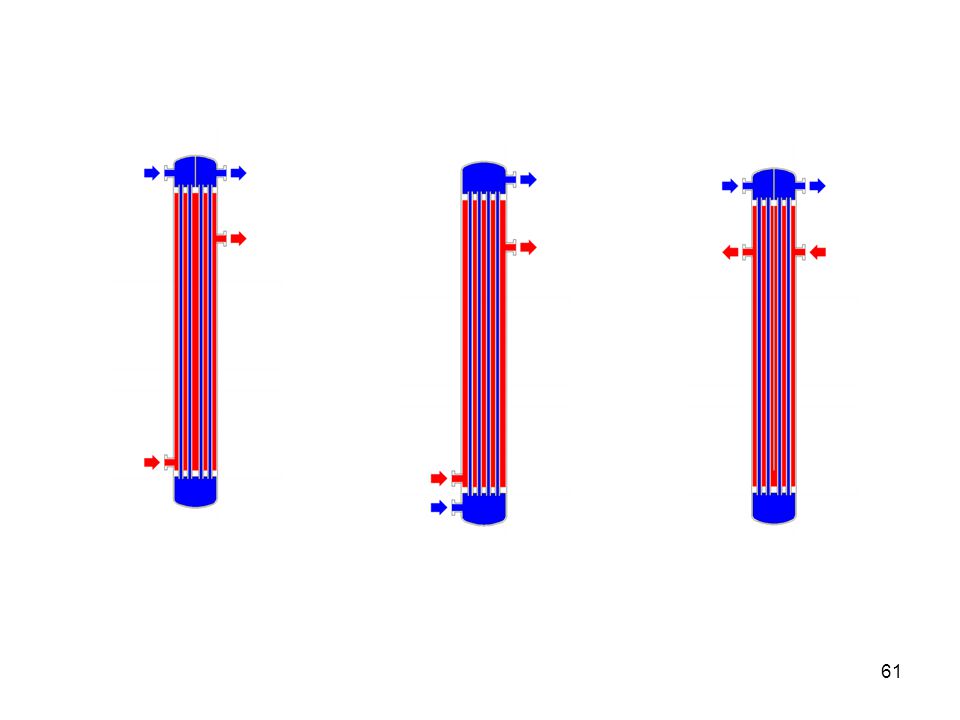
Most shell-and-tube heat exchangers are either 1, 2, or 4 pass designs on the tube side. This refers to the number of times the fluid in the tubes passes through the fluid in the shell. In a single pass heat exchanger, the fluid goes in one end of each tube and out the other.

64
Surface condensers in power plants are often 1-pass straight-tube heat exchangers.
In other facilities such as refineries, two and four pass designs are common because the fluid can enter and exit on the same side. This makes construction much simpler.

65
There are often baffles directing flow through the shell side so the fluid does not take a short cut through the shell side leaving ineffective low flow volumes. Countercurrent heat exchangers are most efficient because they allow the highest log mean temperature difference between the hot and cold streams.

66
Many companies however do not use single pass heat exchangers because they can break easily in addition to being more expensive to build. Often multiple heat exchangers can be used to simulate the countercurrent flow of a single large exchanger.

67
Selection of tube material
To be able to transfer heat well, the tube material should have good thermal conductivity. Because heat is transferred from a hot to a cold side through the tubes, there is a temperature difference through the width of the tubes. Because of the tendency of the tube material to thermally expand differently at various temperatures, thermal stresses occur during operation.

68
Tube material The tube material also should be compatible with both the shell and tube side fluids for long periods under the operating conditions (temperatures, pressures, pH, etc.) to minimize deterioration such as corrosion. All of these requirements call for careful selection of strong, thermally-conductive, corrosion-resistant, high quality tube materials, typically metals. Poor choice of tube material could result in a leak through a tube between the shell and tube sides causing fluid cross-contamination and possibly loss of pressure.
 to minimize deterioration such as corrosion. All of these requirements call for careful selection of strong, thermally-conductive, corrosion-resistant, high quality tube materials, typically metals. Poor choice of tube material could result in a leak through a tube between the shell and tube sides causing fluid cross-contamination and possibly loss of pressure.")
69
The Tubular Exchanger Manufacturers Association, Inc.
(TEMA) is trade association of leading manufacturers of shell and tube heat exchangers, who have pioneered the research and development of heat exchangers for over sixty years. The TEMA Standards and software have achieved worldwide acceptance as the authority on shell and tube heat exchanger mechanical design.
 is trade association of leading manufacturers of shell and tube heat exchangers, who have pioneered the research and development of heat exchangers for over sixty years. The TEMA Standards and software have achieved worldwide acceptance as the authority on shell and tube heat exchanger mechanical design.")
70
TEMA members are market-aware and actively involved, meeting several times a year to discuss current trends in design and manufacturing. The internal organization includes various subdivisions committed to solving technical problems and improving equipment performance.

71
TEMA Choosing the right supplier is an important and difficult decision. Users need to be absolutely sure that their manufacturer is reliable, producing heat transfer equipment that is safe, effective, and economical. Considerable time and money are spent having a heat exchanger designed and built to exact specifications, design codes and requirements. TEMA, was founded in 1939 and has grown to include a select group of member companies. Members adhere to strict specifications. TEMA members develop and update today's standards. TEMA Standards and Software have achieved worldwide acceptance as the authority on shell and tube heat exchanger mechanical design.

72
TEMA TEMA has also developed engineering software that complements the TEMA Standards in the areas of flexible shell elements (expansion joints) analysis, flow induced vibration analysis and fixed tubesheet design and analysis. This state-of-the-art software features a materials data-bank of 38 materials. The programs handle many complex calculations, so users can focus on the final results.
 analysis, flow induced vibration analysis and fixed tubesheet design and analysis. This state-of-the-art software features a materials data-bank of 38 materials. The programs handle many complex calculations, so users can focus on the final results.")
73
TEMA Before a company can even become a member of TEMA, it must have a minimum of 5 years of continuous service in the manufacture, design and marketing of shell and tube heat exchangers. All TEMA companies must have in-house thermal and mechanical design capabilities, and thoroughly understand current code requirements and initiate strict quality control procedures. Additionally, all welding must be done by the company's own personnel, and the company must have its own quality control inspectors.

74
Tubular Exchanger Manufacturers Association, Inc.
8th Edition of the Standards of the Tubular Exchanger Manufacturers Association sections have been reviewed to incorporate new data which were not available at the time of the 1988 printing, including suggestions which resulted from the extensive use of the Standards by both manufacturers and users of shell and tube heat exchangers. cooperation of the American Petroleum Institute (API) and the American Society of Mechanical Engineers (ASME)
 and the American Society of Mechanical Engineers (ASME)")
75
TEMA’s Eighth Edition:
Metrification has been included where feasible and appropriate. Methods for calculating several types of floating head backing rings have been added. A method for incorporating pass partition rib area into flange design has been incorporated. The vibration section has been expanded and vibration amplitude for vortex shedding and acoustic resonance have been added. Nozzle flange pressure/temperature rating tables from ASME Standard B w/ 1998 addenda are included.

76
TEMA’s Eighth Edition:
New materials have been included in coefficient of thermal expansion, modulus of elasticity, and thermal conductivity tables. Design equations for double tubesheets have been added. A method for calculating the mean metal temperature for tubesheets has been added. Stress multipliers have been added to account for the stiffness of knuckles on flanged and flued expansion joints. Suggested calculation methods have been incorporated for both vertical and horizontal supports. Design methods have been added for lifting lugs.

77
More on T-Q Ticket to HX design and rating Basis for Heat Integration
Used for process design

78
QUICK REVIEW

79
Industrial Furnaces

80
Overview and Content Background Definitions Key Areas Steam reformer

81
fuel + air oxidation products
Fired Heaters are used widely in chemical processing and petroleum refining plants supply heat to various process fluids by burning fuel in a combustion chamber fuel is usually oil or gas or a combination burners are placed on the floor of the heater or on the wall

82
Heat Transfer Mechanisms
Radiation (T4) Conduction (DTsolid) Convection (DTconvective film)
 Conduction (DTsolid) Convection (DTconvective film)")
83
Radiation tubes are installed along the walls and roof
combustion chamber called radiant section heat is transferred to the tube wall primarily by radiation flue gases are then passed through the convection section of the heater

84
Convection Section Characterized by extended surfaces
fins or studs improve heat transfer increase effective area required area governed by LMTD and Uo Economical heat recovery steam generation boiler feed water preheat combustion air preheat Flue gas passes through a stack to the atmosphere

85
Convection Section outside film outside fouling tube wall inside film
Typical Indirect heat transfer mechanism T bulk outside outside film outside fouling tube wall inside film inside fouling T bulk inside

86
most of the heat is transferred in the radiant section
Radiant Efficiency => Radiant Duty/Fired Duty Overall Efficiency => Absorbed Duty/Fired Duty In large heaters most of the heat is transferred in the radiant section Convection section increases the overall efficiency of the heater Some fired heaters, for very low heat duty services, have no convection section thermal efficiency lowest capital investment. Most fired heaters have both a radiant and convection section New-fired heaters air preheating system NOx reduction system

87
Process Fluid: Fluid characteristics of the process fluids should be considered before designing a heater. for example, Very high viscosity fluids have tendency to attain very high film temperature, as the fluid in the film does not readily mix with the bulk fluid. This results in uneven distribution of heat in the fluid and develops hot spots, where vaporization and degradation occurs.

88
Heat Duty: Total furnace heat duty sum of heat transferred to all process streams, including auxiliary services such as steam superheaters. Amount of heat duty affects the selection of type and configuration of heater.

91
What Flue Gas Temperature Tells Us
Flue gas temperature is an indication of how effectively combustion heat is being transferred to the boiler water. In general, lower flue gas temperature indicates better heat transfer and higher overall efficiency. It means that less energy is going up the stack and, everything else being equal, more is going into the water. If you find flue gas temperature gradually increasing over time, this indicates gradually deteriorating heat transfer within the boiler. This could be caused by soot buildup on the fire side of the heat transfer surfaces, or scale buildup on the water side. A flue gas temperature increase of 100°C indicates a boiler efficiency decrease of 4 to 5 per cent.

92
Average Radiant Heat Flux:
Average radiant heat flux rate is very important parameter for design of a fired heater. Higher the design radiant flux, less the heat transfer surface, smaller the heater and lower the cost. Unduly high radiant rates, however, result in higher maintenance cost due to shortened life of components and coke deposition. Allowable average radiant heat flux rate is a function of various factors such as heater type, feedstock, service, coil outlet temperature etc. and, therefore, established by experience.

93
Mass Flow Velocity: Cracking and polymerization occur in the film of the fluid inside the tube wall surface. To minimize coking and fouling in coils, fired heaters should be designed with high enough mass velocities. However, too high a mass velocity will cause a high coil pressure drop, resulting in high pumping or compressor costs, increased design pressure of the coils and upstream equipment and possible erosion at the heater return bends. Design mass velocity is usually kept in the range of 250 to 350 lb/sec-ft2. Under turndown conditions, mass velocity should be kept above 150 lb/sec-ft2 in order to prevent excessive coking and fouling of the coils.

94
Vaporization in Process Fired Heaters:
It is desirable to avoid a situation when the liquid or partially vaporized stream reaches a point within the heater in which it is 100% vaporized. Foreign material or polymer formed in tankage, which does not vaporize, may deposit on the tube and cause coking. Therefore, limit the maximum vaporization to about 80%.

95
Tube size, Number of Passes and Fluid Pressure Drop:
A combination of the tube size and number of passes is selected to satisfy the mass flow velocity, throughput and fluid pressure drop requirements. Tube diameters are normally selected from standard tube sizes, in the range of 3 to 8 inches. Non-standard sizes can also be used when design parameters cannot be met with standard sizes.

96
Turndown: Turndown requirements are set by process considerations. In general, turndown rates of 60% can be used without falling below mass velocity rates needed to prevent excessive coking rates.

97
Burner turndown is a function of burner design and the type of fuel.
However, burner turndown does not normally affect furnace turndown, but burners can be turned off or excess air increased when furnace is operated at greatly reduced firing rates.

98
Stack Temperature and Optimum Heater Efficiency:
The economic stack temperature or the optimum efficiency of the heater is a function of fuel value, inlet oil temperature, investment cost of the incremental convection section and the required rate of return from incremental investment. Stack temperature usually ranges from 350°F to 700°F, however, a temperature of 250°F can be achieved for low sulfur fuel using air preheater. Stack temperature must be high enough to prevent acid condensation on the convection section inlet tubes and air preheater. Most of the new fired heaters have convection sections and air preheater. As a result, heater efficiencies have increased to more than 90%.

99
Tube/Coil Materials: Heater tubes are usually made from carbon steel, alloy steel or stainless steel pipes. Tubing material is selected based on service life, corrosion resistance and cost. Allowable stresses in the tube material decrease with increasing temperatures, therefore, higher tube temperatures require thicker tubewalls or higher alloy-content. Carbon steel is the most widely used material for heater tubing where corrosion resistance is relatively mild.

100
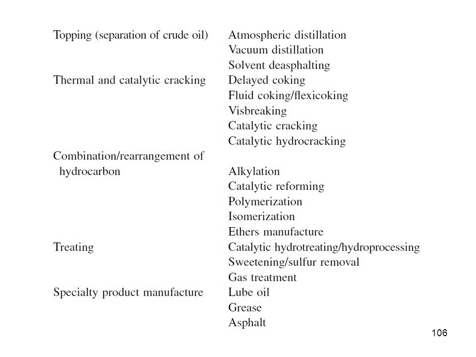
Applications

102
In addition to the books by Reed and Zink, Inc.
A nice reference:

104
Fired Heaters or Furnaces, are used for various purposes in the Refining & Petrochemical Industry, Power Generation Facilities and in Homes and Apartments, etc. In refineries applications include: Air Heater, Boilers, Reboilers, Vacuum Charge Heater, Crude Furnace, Hydrocracker, Pyrolysis Furnace, Reforming Furnace, Visbreaker Furnace, etc.

107
Industrial burners handbook
By Charles E. Baukal

111
The first step in the refining process is the separation of crude oil into various fractions or straight-run cuts by distillation in atmospheric and vacuum towers. The main fractions or "cuts" obtained have specific boiling-point ranges and can be classified in order of decreasing volatility into gases, light distillates, middle distillates, gas oils, and residuum At the refinery, the desalted crude feedstock is preheated using recovered process heat. The feedstock then flows to a direct-fired crude charge heater where it is fed into the vertical distillation column just above the bottom, at pressures slightly above atmospheric and at temperatures ranging from 650° to 700° F All but the heaviest fractions flash into vapor. As the hot vapor rises in the tower, its temperature is reduced.

112
VACUUM DISTILLATION PROCESS
In order to lower the temperatures in further distilation of residual crude from the atmospheric tower, reduced pressure. Vacuum towers may produce gas oils, lubricating-oil base stocks, and heavy residual. Vacuum towers are typically used to separate catalytic cracking feedstock from surplus residuum.

113
Hydrocracking Process
Hydrocracking Process. In the first stage, preheated feedstock is mixed with recycled hydrogen and sent to the first-stage reactor, where catalysts convert sulfur and nitrogen compounds to hydrogen sulfide and ammonia. Limited hydrocracking also occurs. After the hydrocarbon leaves the first stage, it is cooled and liquefied and run through a hydrocarbon separator. The hydrogen is recycled to the feedstock. The liquid is charged to a fractionator. Depending on the products desired (gasoline components, jet fuel, and gas oil), the fractionator is run to cut out some portion of the first stage reactor out-turn. Kerosene-range material can be taken as a separate side-draw product or included in the fractionator bottoms with the gas oil.
, the fractionator is run to cut out some portion of the first stage reactor out-turn. Kerosene-range material can be taken as a separate side-draw product or included in the fractionator bottoms with the gas oil.")
114
VISBREAKING PROCESS Visbreaking, a mild form of thermal cracking, significantly lowers the viscosity of heavy crude-oil residue without affecting the boiling point range. Residual from the atmospheric distillation tower is heated ( degrees F) at atmospheric pressure and mildly cracked in a heater. It is then quenched with cool gas oil to control overcracking, and flashed in a distillation tower. Visbreaking is used to reduce the pour point of waxy residues and reduce the viscosity of residues used for blending with lighter fuel oils. Middle distillates may also be produced, depending on product demand. The thermally cracked residue tar, which accumulates in the bottom of the fractionation tower, is vacuum flashed in a stripper and the distillate recycled.
 at atmospheric pressure and mildly cracked in a heater. It is then quenched with cool gas oil to control overcracking, and flashed in a distillation tower. Visbreaking is used to reduce the pour point of waxy residues and reduce the viscosity of residues used for blending with lighter fuel oils. Middle distillates may also be produced, depending on product demand. The thermally cracked residue tar, which accumulates in the bottom of the fractionation tower, is vacuum flashed in a stripper and the distillate recycled.")
115
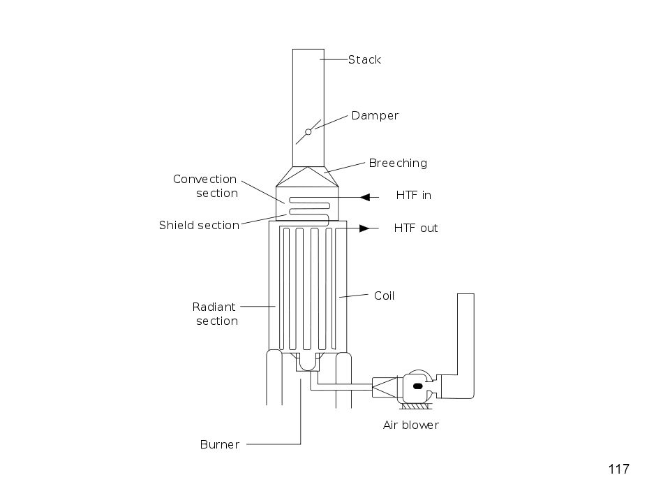
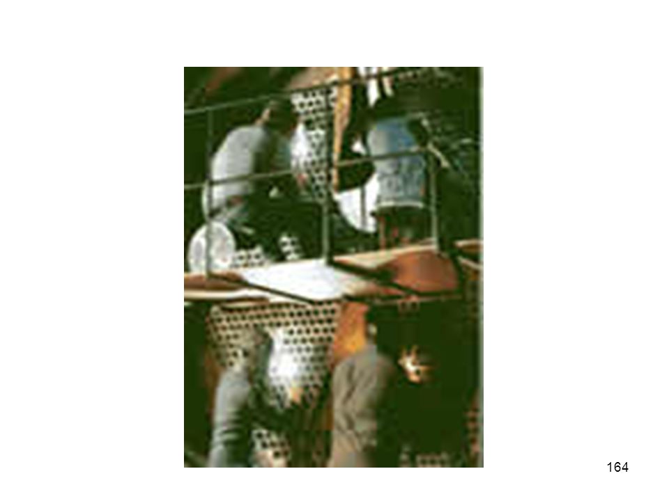
Fired Heater Components

118
Burner

119
Fired Heater With Air Preheat

120
Importance of Draft Fired heaters are major consumers of energy in the chemical process industries (CPI), especially at petroleum refineries and petrochemical plants--accounting for as much as 70% of total plant consumption in some instances. While most plant engineers and operators are aware of the importance of controlling excess oxygen in fired heaters, they often overlook a key determinant of efficient heater operation: the control of their draft, namely, the negative pressure inside the vessel with respect to the atmosphere.
, especially at petroleum refineries and petrochemical plants--accounting for as much as 70% of total plant consumption in some instances. While most plant engineers and operators are aware of the importance of controlling excess oxygen in fired heaters, they often overlook a key determinant of efficient heater operation: the control of their draft, namely, the negative pressure inside the vessel with respect to the atmosphere.")
121
In most fired heaters, the draft is maintained at almost four times the value recommended.
At the other end of the spectrum, some heaters run with no draft--in fact, with positive pressure at the radiant arch (the transition zone between the radiant and convection sections). Neither situation is desirable; they can cause considerable loss of energy, and can even be hazardous.
. Neither situation is desirable; they can cause considerable loss of energy, and can even be hazardous.")
123
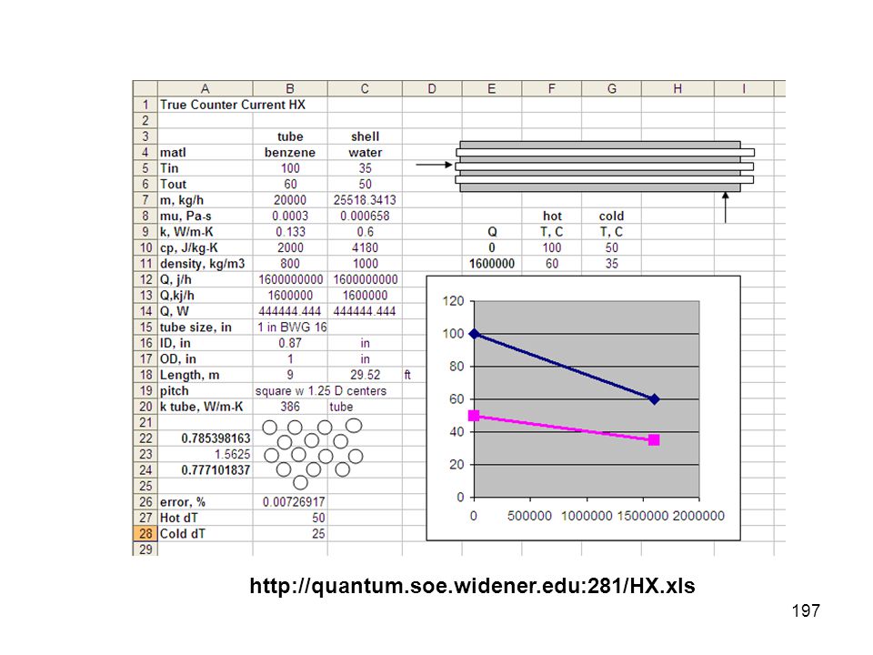
ZONE ANALYSIS defined as regimes of phase changes where the overall heat transfer coefficient (Uo) will vary Using T-Q (Temperature-Heat) diagrams are the best way to pinpoint zones. Chemical #1 enters the shell at 200 0C as a superheated vapor. In Zone 1, it releases heat to the tubeside chemical (Chemical #2). Zone 1 ends just a Chemical #1 begins to condense. The tubeside (Chemical #2) enters as a liquid or gas and does not change phase throughout the exchanger.
 diagrams are the best way to pinpoint zones. Chemical #1 enters the shell at 200 0C as a superheated vapor. In Zone 1, it releases heat to the tubeside chemical (Chemical #2). Zone 1 ends just a Chemical #1 begins to condense. The tubeside (Chemical #2) enters as a liquid or gas and does not change phase throughout the exchanger.")
124
ZONE ANALYSIS Chemical #1 leaves Zone 1 and enters Zone 2 at its boiling temperature, Tb1. T* marks the temperature of Chemical #2 when Chemical #1 begins to condense. In Zone 2, Chemical #1 condenses to completion while Chemical #2 continues to increase in temperature. The temperature of Chemical #2 when Chemical #1 is fully condensed is denoted at T**. Finally, in Zone 3, both chemicals are liquids. Chemical #1 is simply liberating heat to Chemical #2 as it becomes a subcooled liquid and exits the shell at 100 0C.

125
ZONE ANALYSIS Defining zones is one of the most important aspects of heat exchanger design. It is also important to remember that if a process simulator does not support zoned analysis you should model each zone with a separate heat exchanger. Thus, the previous illustration would require 3 heat exchangers in the simulation and also may require three separate bundles in the real plant.

126
GJM Procedure, part 1 Assemble Physical Properties
Assemble Service Requirements Construct T-Q Diagram Establish Zones and Calculate LMTD Guess a Uo Calculate Required Surface Area

127
GJM Procedure, part 2 Pick Tube Dimensions Calculate Number of Tubes
size, gauge, length Calculate Number of Tubes Calculate Flow Characteristics on Shell and Tube Sides Velocity, Re, Pr, Nu Calculate hi, ho

128
GJM Procedure, part 3 Calculate Uo Check versus Assumed Uo
Iterate or Goal Seek (Excel) Until the Uo Matches Calculate Pressure Drop
 Until the Uo Matches. Calculate Pressure Drop.")
129
If using a process simulator, obtaining the physical properties of the streams are easy.
Get the physical properties for each zone separately to ensure accuracy, but in some cases it is acceptable to use an average value. This would be true for sensible heat transfer since the material is not changing phase or undergoing a truly significant temperature change (over 1000C). Physical properties will include: heat capacity, viscosity, thermal conductivity, density, and latent heat (for phase changes). These are in addition to the boiling points of the streams at their respective pressures.
. Physical properties will include: heat capacity, viscosity, thermal conductivity, density, and latent heat (for phase changes). These are in addition to the boiling points of the streams at their respective pressures.")
130
Guessing Uo Estimates for the heat transfer coefficients can be found in most textbooks Main equation Q=UoADTlm The above equation must be used to get an area for each zone, then add them together.

132
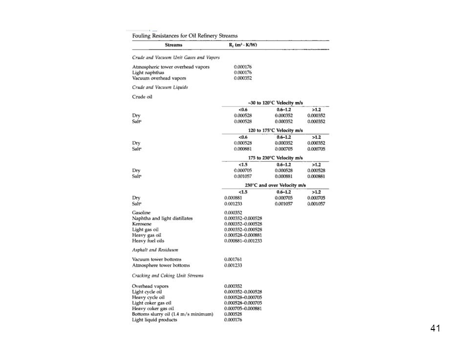
The determination of U is often tedious and needs data not yet available in preliminary stages of the design. Therefore, typical values of U are useful for quickly estimating the required surface area. The literature has many tabulations of such typical coefficients for commercial heat transfer services. Lower values are for unfavorable conditions such as lower flow velocities, higher viscosities, and additional fouling resistances. Higher values are for more favorable conditions. Coefficients of actual equipment may be smaller or larger than the values listed. Note that the values should not be used as a replacement of rigorous methods for the final design of heat exchangers, although they may serve as a useful check on the results obtained by these methods.

133
What geometric configuration is right for the exchanger?
Once you've selected a shell diameter, tubesheet layout, baffle and tube spacing, etc., it's time to check your velocity and pressure drop requirements to see if they're being met. Experienced designers will usually combine these steps and actually obtain a tube size that meets the velocity and pressure drop requirements and then proceed. Some guidelines may be as follows: 3/4 in. and 1.0 in. diameter tubes are the most popular and smaller sizes should only be used for exchangers needing less than 30 m2 of area. If your pressure drop requirements are low, avoid using four or more tube passes as this will drastically increase your pressure drop.

134
This is where you'll spend much of your time in designing a heat exchanger. Although many textbooks show Nu=0.027(NRE)0.8(NPR)0.33 as the "fundamental equation for turbulent flow heat transfer", what they sometimes fail to tell you is that the exponents can vary widely for different situations. For example, condensation in the shell has different exponents than condensation in the tubes. Use this fundamental equation if you must, but you should consult a good resource for accurate equations.
0.8(NPR)0.33. as the fundamental equation for turbulent flow heat transfer , what they sometimes fail to tell you is that the exponents can vary widely for different situations. For example, condensation in the shell has different exponents than condensation in the tubes. Use this fundamental equation if you must, but you should consult a good resource for accurate equations.")
136
Lytron's heat exchanger technologies include tube-fin, oil cooler, plate-fin, and liquid-to-liquid brazed plate heat exchangers. With almost five decades of experience in heat exchanger design and manufacturing, Lytron's expertise is second-to-none. Our heat exchangers are used in many industries including military and aerospace, medical and industrial lasers, medical imaging, analytical instrumentation, power electronics, semiconductor equipment, machine tools and telecommunications. Any of our heat exchanger technologies can be customized to your exact requirements. We also supply heat exchanger subassemblies, adding fittings, hoses, fans, sensors and other instrumentation to your specification. And our seven product ranges with over 130 standard parts ensure that when you need an off-the-shelf part we are likely to have something that meets your requirements. Lytron’s broad range of heat exchanger technologies combined with almost five decades of thermal transfer experience enables us to offer tailored solutions for a wide range of applications. Our tube-fin, oil cooler, plate-fin, and liquid-to-liquid brazed plate heat exchangers can all be customized and integrated into subassemblies. Performance comparison This chart compares the performance of different heat exchanger technologies, including plate-fin, oil cooler, and tube-fin heat exchangers. Performance is shown as Q/ITD, the heat load divided by the difference in incoming temperature of the liquid and air. Units are not shown so that technologies can be compared regardless of size.As many heat exchangers are customized, a range of typical values is shown for each technology. All performances are compared using water as the cooling fluid. Fluid compatibility Coolant compatibility with wetted surfaces must be considered when selecting a heat exchanger technology. A copper fluid path is compatible with water and most common coolants. A stainless steel fluid path is necessary when using deionized water and other corrosive fluids. Aluminum offers excellent performance with ethylene glycol/water mixture (EGW), oils and other fluids, but is not compatible with untreated water. The table below shows fluid/heat exchanger compatibility.
, oils and other fluids, but is not compatible with untreated water. The table below shows fluid/heat exchanger compatibility.")
137
ME-143 Principles of Heat Exchanger Design, Part II
This seminar provides a continuation of the discussion of the equipment used for the transfer of heat. Specific examples and case studies will highlight analysis techniques and step-wise procedures. Emphasis will be placed on the calculation of the film coefficient for a variety of different geometries and how to compose an overall heat transfer coefficient. Transfer line exchangers, plate-fin exchangers and Joule-Thompson exchangers are among the examples covered.

138
Energy Balance Mechanical design and process arrangement
Outline Heating and cooling requirements Indirect or direct heat transfer Various types of heat exchangers Mechanical design and process arrangement Key vendors and producers Tubular Exchanger Manufacturers Association

139
What is Heat ? Universe: matter and energy
Energy causes the atoms and molecules to always be in motion Motion of atoms and molecules creates heat or thermal energy In space, matter still has a very small amount of heat energy

140
What is Heat ? Cal Tech Image Using IR

141
Force, Pressure, Work, Energy, Power
Force: Newton, (kg)(m)(s-2) Pressure: Pascal, (N)(m-2) Work: Joule, (N)(m) Energy: Joule, (N)(m) Power: Watt, (J)(s-1) Example: a 60 W light bulb expends 216 kJ every hour of use and costs the consumer about 1 cent (US)
(m)(s-2) Pressure: Pascal, (N)(m-2) Work: Joule, (N)(m) Energy: Joule, (N)(m) Power: Watt, (J)(s-1) Example: a 60 W light bulb expends 216 kJ every hour of use and costs the consumer about 1 cent (US)")
142
Energy in Colloquial Terms
1 BTU = 1055 J 1 BTU = kJ 1 kWh = 3600 kJ Energy in Colloquial Terms kWh = 1 kJ/s of power expended for 1 h Cost (based on PECO): $0.165/kWh
: $0.165/kWh.")
143
Current Energy Production Picture – US and World-Wide
Language of Energy Production and Usage Magnitude Energy Needs Environmental Impact as a energy and environmental primer: in combustion: 1 kg C yields ~ 3.7 kg CO2 and ~ 33 MJ

144
Unit Levels – SI Prefixes
1 EW exa 103 PW peta 106 TW tera 109 GW giga 1012 MW mega 1015 kW kilo 1018 W ----- 1021 mW milli 1024 mW micro

145
World Energy Consumption
Fuel type Power in TW Energy in EJ Oil 5.6 180 Gas 3.5 110 Coal 3.8 120 Hydroelectric 0.9 30 Nuclear Geothermal, wind, solar, wood 0.13 4 Total 15 471 as a reference: 174,000 TW (174 PW) incoming solar power
 incoming solar power.")
146
Value of Energy - Energy Information Administration
Price Summary Year 2007 2008 2009 2010 WTI Crude ($/barrel) 72.32 99.57 60.12 72.42 Gasoline ($/gal) 2.81 3.26 2.34 2.7 Diesel ($/gal) 2.88 3.8 2.47 Heating Oil ($/gal) 2.72 3.38 2.51 2.78 Natural Gas ($/mcf) 13.03 13.67 11.92 11.56 Electricity (cents/kwh) 10.65 11.36 11.64 11.4
 Gasoline ($/gal) Diesel ($/gal) Heating Oil ($/gal) Natural Gas ($/mcf) Electricity (cents/kwh)")
147
Basic Heat Balance The First Law of Thermodynamics:
expression of the principle of conservation of energy states that energy can be transformed but is not created or destroyed

148
not viable in most situations Indirect streams do not mix
Heat Transfer Direct stream mixing cheap not viable in most situations Indirect streams do not mix

149
Heat Transfer Mechanisms
Conduction Convection Radiation

150
Conduction Transfer of thermal energy (heat) from a region of higher temperature to a region of lower temperature by direct contact (Second Law of Thermodynamics)
 from a region of higher temperature to a region of lower temperature by direct contact (Second Law of Thermodynamics)")
151
Conduction Direct molecular communication without a flow of material Metals (eg. copper) are usually the best conductors of thermal energy. Fluids are not typically good conductors. HX tubes are usually made of copper, CS, or SS
 are usually the best conductors of thermal energy. Fluids are not typically good conductors. HX tubes are usually made of copper, CS, or SS.")
152
Convection combination of conduction and the transfer of thermal energy by fluid circulation or movement of the hot particles in bulk to cooler areas in a material medium. T bulk convective film coefficient T surface

153
This movement occurs into a fluid or within a fluid, and cannot happen in solids In solids, molecules keep their relative position to such an extent that bulk movement or flow is impossible

154
Radiation Transfer of heat through electromagnetic radiation Objects radiate energy at a rate equal to their emissivity times the rate at which energy would radiate from them if they were perfect radiators

155
Radiation No medium is necessary for radiation to occur; radiation works even in and through a perfect vacuum

156
Radiation Reflectivity and emissivity of all bodies is wavelength dependent Temperature determines the wavelength distribution of the electromagnetic radiation

157
HOT Stream – loses heat Direct Mixing COLD Stream – gains heat

158
Indirect Heat Exchange
countercurrent HOT Stream – loses heat COLD Stream – gains heat

159
Indirect Heat Exchange
cocurrent HOT Stream – loses heat COLD Stream – gains heat

160
Heat Transfer Equations Beginnings of a T-Q Curve
Q, kJ/h heat transferred l, latent heat cp, specific heat

161
Shell and tube heat exchanger
Indirect heat transfer Most common type of heat exchanger in oil refineries and other large chemical processes Suited for higher-pressure applications

162
Shell and tube heat exchanger
Consists of a shell (a large pressure vessel) with a bundle of tubes inside it. One fluid runs through the tubes, and another fluid flows over the tubes (through the shell) to transfer heat between the two fluids. The set of tubes is called a tube bundle, and may be composed by several types of tubes: plain, longitudinally finned, etc.
 with a bundle of tubes inside it. One fluid runs through the tubes, and another fluid flows over the tubes (through the shell) to transfer heat between the two fluids. The set of tubes is called a tube bundle, and may be composed by several types of tubes: plain, longitudinally finned, etc.")
163
Shell and tube heat exchanger design
There can be many variations on the shell and tube design. Typically, the ends of each tube are connected to plenums (sometimes called water boxes) through holes in tubesheets. The tubes may be straight or bent in the shape of a U, called U-tubes.
 through holes in tubesheets. The tubes may be straight or bent in the shape of a U, called U-tubes.")
166
The Tubular Exchanger Manufacturers Association, Inc.
TEMA The Tubular Exchanger Manufacturers Association, Inc. (TEMA) is trade association of leading manufacturers of shell and tube heat exchangers, who have pioneered the research and development of heat exchangers for over sixty years. The TEMA Standards and software have achieved worldwide acceptance as the authority on shell and tube heat exchanger mechanical design.
 is trade association of leading manufacturers of shell and tube heat exchangers, who have pioneered the research and development of heat exchangers for over sixty years. The TEMA Standards and software have achieved worldwide acceptance as the authority on shell and tube heat exchanger mechanical design.")
167
TEMA Mission Users need to be absolutely sure that their manufacturer is reliable, producing heat transfer equipment that is safe, effective, and economical. Considerable time and money are spent having a heat exchanger designed and built to exact specifications, design codes and requirements.

168
TEMA History TEMA, was founded in 1939 and has grown to include a select group of member companies. Members adhere to strict specifications TEMA members develop and update today's standards. TEMA Standards and Software have achieved worldwide acceptance as the authority on shell and tube heat exchanger mechanical design

169
TEMA Outreach and Standards
TEMA members are market-aware and actively involved, meeting several times a year to discuss current trends in design and manufacturing The internal organization includes various subdivisions committed to solving technical problems and improving equipment performance

170
ThomasNet for HX Vendors

171
Side-by-Side Comparisons
ThomasNet for HXs Side-by-Side Comparisons

172
Heat Exchangers: Shell & Tube Icon
Tube Side Shell Side

173
Heat Exchangers: Shell & Tube Icon

174
Overview of HX Design – Part 1
Equipment used for the transfer of heat energy Basic heat balance as a T-Q curve Appropriate TEMA designation Economic and environmental considerations Pinch Technology for heat exchanger networks

175
Fluid Flow Arrangements
The fluids can be either liquids or gases on either the shell or the tube side. In order to transfer heat efficiently, a large heat transfer area should be used, so there are many tubes. In this way, waste heat can be put to use. This is a great way to recuperate energy.

176
Sensible Heat Transfer
vs Phase Change Heat exchangers with only one phase (liquid or gas) on each side can be called one-phase or single-phase heat exchangers Two-phase heat exchangers can be used to heat a liquid to boil it into a gas (vapor), sometimes called boilers, or cool a vapor to condense it into a liquid (called condensers), with the phase change usually occurring on the shell side.
 on each side can be called one-phase or single-phase heat exchangers. Two-phase heat exchangers can be used to heat a liquid to boil it into a gas (vapor), sometimes called boilers, or cool a vapor to condense it into a liquid (called condensers), with the phase change usually occurring on the shell side.")
177
Amongst the Largest HXs are…..
In large power plants with steam-driven turbines, shell-and-tube surface condensers are used to condense the exhaust steam exiting the turbine into condensate water which can be recycled back to be turned into steam, possibly into a shell-and-tube type boiler

179
Heat Exchangers: Shell & Tube Arrangement

182
TEMA Front, Shell, Rear Designation

183
Sample CFU (top) AKT (bot)
 AKT (bot)")
184
CFU Designation (C). Channel Integral with. Fixed Tube Sheet (F)
CFU Designation (C) Channel Integral with Fixed Tube Sheet (F) Two Pass Shell with Longitudinal Baffle (U) U-tube (two pass tubes)
 Channel Integral with Fixed Tube Sheet (F) Two Pass Shell with Longitudinal Baffle (U) U-tube (two pass tubes)")
185
AKT Designation (A). Channel and Removable. Cover (K). Kettle (T)
AKT Designation (A) Channel and Removable Cover (K) Kettle (T) Pull Through Floating Head
 Channel and Removable Cover (K) Kettle (T) Pull Through Floating Head.")
186
Heat Transfer Equations - sign convention
Exothermic – gives off heat Usually written as negative Endothermic – absorbs heat Usually written as positive GJM – “think positively” Using words like heat removed and heat absorbed and plot on the same axis

187
Direct Heat Transfer Example

188
Indirect Heat Transfer Example

189
Indirect Heat Transfer Example

190
Basics Two fluids, of different starting temperatures, flow through the heat exchanger. One flows through the tubes (the tube side) and the other flows outside the tubes but inside the shell (the shell side). Heat is transferred from one fluid to the other through the tube walls, either from tube side to shell side or vice versa. This process is best represented by a T-Q diagram
 and the other flows outside the tubes but inside the shell (the shell side). Heat is transferred from one fluid to the other through the tube walls, either from tube side to shell side or vice versa. This process is best represented by a T-Q diagram.")
191
Indirect Heat Transfer Example
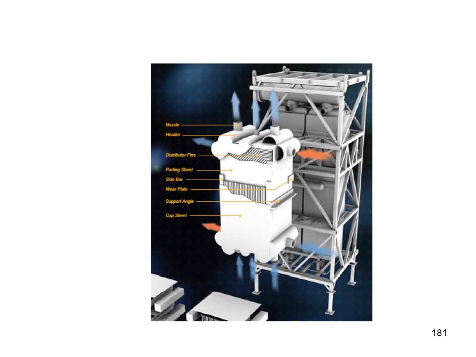
Plate and Frame Heat Exchanger

192
2nd Law of Thermodynamics - Bottom Line
At every point in the HX, the hot stream must be hotter than the cold stream by a distance called the driving force

193
J-T Heat Exchanger System With Brazed
Aluminum Type plate Exchanger

194
Composite Curves in the Plate Exchanger
composite cold curve

195
Overview of HX Design – Part 2
Step 1: Gather duty requirements and physical properties Step 2: Construct a T-Q Curve Step 3: Guess an Overall Heat Transfer Coefficient Step 4: Calculate the LMTD Step 5: Calculate the F (correction factor) Step 6: Calculate the Heat Transfer Area
 Step 6: Calculate the Heat Transfer Area.")
196
Overview of HX Design – Part 2
Step 7: Assign the tube specifications – diameter, BWG and length Step 8: Calculate the outside surface area per tube Step 9: Calculate the number of tubes to provide the required area Step 10: Calculate the velocity - shell side and tube side Step 11: Calculate the tube and shell side coefficients Step 12: Calculate the Overall Heat Transfer Coefficient Step 13: Check with Step 3, adjust and recalculate

200
Outline Assessing the performance of a heat exchanger Value of energy transferred Capital cost of the heat exchanger Economic performance Economic sensitivity

201
Assessing the Performance of a Heat Exchanger
Outline Leveraging issues, such as the level of energy transferred Fouling, cleaning and sparing philosophy Future of heat exchanger design New technology Breakthrough design options

202
Assessing the performance of a heat exchanger
Calculate the required heat transfer area and the associated cost Calculate the cost of any utility or utility savings Perform an economic analysis based on delta costs and delta returns – that is will additional surface area of a heat exchanger provide a high enough reduction in utility costs

203
Assessing the performance of a heat exchanger
Energy Cost Heat Exchanger Area

204
Value of Level of Heat/Cooling

205
Value of Level of Heat/Cooling

206
Value of Level of Heat/Cooling

207
Basics of Pinch Technology for Heat Integration
Pinch technology presents a simple methodology for systematically analyzing chemical processes and the surrounding utility systems with the help of the First and Second Laws of Thermodynamics. The temperature approach is the minimum allowable temperature difference (DTmin) in the stream temperature profiles, for the heat exchanger unit.
 in the. stream temperature profiles, for the heat exchanger. unit.")
208
Basics of Pinch Technology for Heat Integration, continued….
The temperature level at which DTmin is observed in the process is referred to as "pinch point" or "pinch condition" The pinch defines the minimum driving force allowed in the exchanger unit.

209
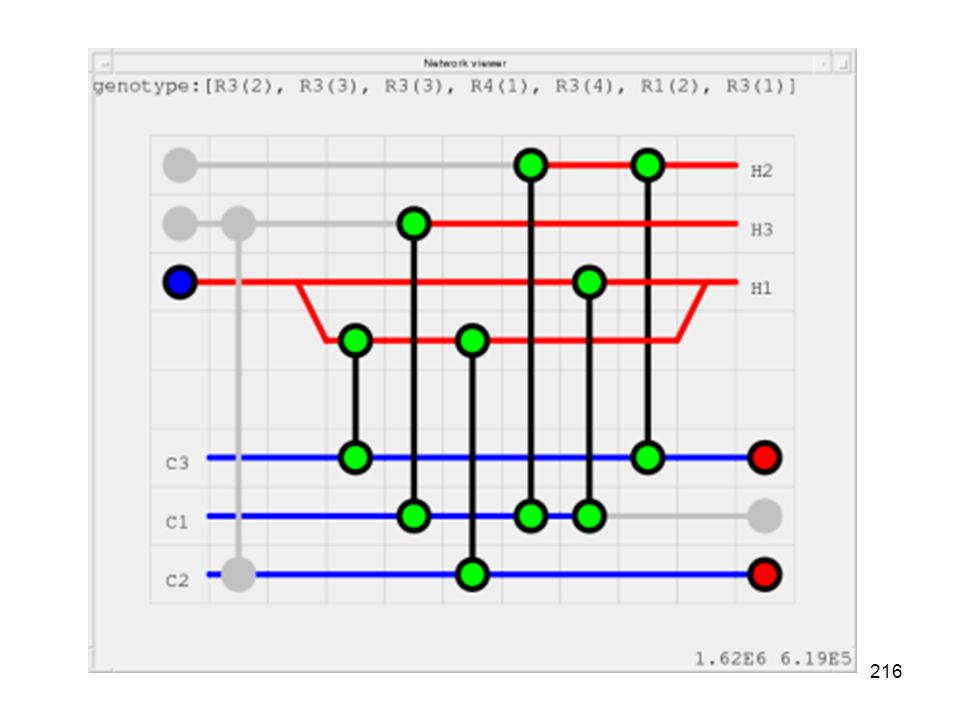
Objectives of Pinch Technology for Heat Integration
Pinch Analysis is used to identify energy cost and heat exchanger network (HEN) capital cost targets for a process and recognizing the pinch point The procedure first predicts, ahead of design, the minimum requirements of external energy, network area, and the number of units for a given process at the pinch point
 capital cost targets. for a process and recognizing the pinch point. The procedure first predicts, ahead of design, the. minimum requirements of external energy, network. area, and the number of units for a given process at. the pinch point.")
211
Composite Curves for Hot and Cold Streams

212
T-Q Curves for Composite Streams

213
Sliding the Cold Curve

214
Slide a Bit Further

215
Schematic of shell and tube geometry

217
Fouling Buildup on Shell and Tube Side

218
Sample HTCs, BTU/h-ft2-F

220
Novel Heat Exchangers

222
Novel Exchangers

223
Kinex Heat Exchangers

224
True Countercurrent Exchangers

225
Plate Exchangers

226
Questions Give an example of direct heat transfer
Give an example of indirect heat transfer Energy is transferred from hot to cold (T/F ?) What is the main S&T HX design equation? What is a T-Q diagram? Does the T-Q for the cold material intersect the T-Q curve for the hot material? Discontinuities on the T-Q diagram represent phase change (T/F?) What is the main trade organization for S&T HXs? What does LMTD stand for? Provide a reasonable Uo for a gas-gas HX?
 What is the main S&T HX design equation What is a T-Q diagram Does the T-Q for the cold material intersect the T-Q curve for the hot material Discontinuities on the T-Q diagram represent phase change (T/F ) What is the main trade organization for S&T HXs What does LMTD stand for Provide a reasonable Uo for a gas-gas HX")
Similar presentations