Download presentation
Presentation is loading. Please wait.

1
ME421 Heat Exchanger and Steam Generator Design Lecture Notes 7 Part 1 Shell-and-Tube Heat Exchangers

2
Introduction stationary-end headshell rear-end head

3
Introduction Most widely used HEX, round tubes mounted in a shell (cylindrical) One fluid flows inside the tubes, other flows inside the shell Large area-to-volume and area-to-weight ratios Easy to clean Suitable for high-pressure applications and high pressure differences between working fluids Most common applications are as condensers and as steam generators Major components are tubes (tube bundle), shell, front- and rear-end heads, baffles, and tube sheets.
 One fluid flows inside the tubes, other flows inside the shell Large area-to-volume and area-to-weight ratios Easy to clean Suitable for high-pressure applications and high pressure differences between working fluids Most common applications are as condensers and as steam generators Major components are tubes (tube bundle), shell, front- and rear-end heads, baffles, and tube sheets.")
4
Basic Components Shell Types Front and rear head types and shell types are standardized by TEMA, identified by alphabetic characters (Fig. 8.2) E-shell is the most common –cheap and simple configuration –one-shell pass and one- or multiple-tube passes –if one-tube pass, nominal counterflow is achieved –most common for single-phase shell fluid applications F-shell used when there are two tube passes and pure counterflow is desired –longitudinal baffle results in two-shell passes –units in series, each shell pass represents one unit –higher pressure drop than that for E-shell
 E-shell is the most common –cheap and simple configuration –one-shell pass and one- or multiple-tube passes –if one-tube pass, nominal counterflow is achieved –most common for single-phase shell fluid applications F-shell used when there are two tube passes and pure counterflow is desired –longitudinal baffle results in two-shell passes –units in series, each shell pass represents one unit –higher pressure drop than that for E-shell.")
5
Shell Types (continued) J-shell has divided flow –for low pressure drop applications –normally, single nozzle for shell-fluid at tube center, two nozzles near tube ends –when used for condensing the shell fluid, two inlets for shell-side vapor and one central outlet for condensate (figure) X-shell has cross flow –central shell-fluid entry and exit –no baffles are used –very low pressure drop –used for vacuum condensers and low-pressure gases G-shell and H-shell are single- and double-split flow Divided Flow
 J-shell has divided flow –for low pressure drop applications –normally, single nozzle for shell-fluid at tube center, two nozzles near tube ends –when used for condensing the shell fluid, two inlets for shell-side vapor and one central outlet for condensate (figure) X-shell has cross flow –central shell-fluid entry and exit –no baffles are used –very low pressure drop –used for vacuum condensers and low-pressure gases G-shell and H-shell are single- and double-split flow Divided Flow")
6
Shell Types (continued) G-shell and H-shell are single- and double-split flow –G-shell has a horizontal baffle with ends removed, central shell-fluid entry and exit –H-shell is similar, but with two baffles, and two nozzles at the entry and exit K-shell is a “kettle reboiler” –tube bundle covers about 60% of shell diameter –liquid covers the tube bundle, vapor occupies the upper space without tubes
 G-shell and H-shell are single- and double-split flow –G-shell has a horizontal baffle with ends removed, central shell-fluid entry and exit –H-shell is similar, but with two baffles, and two nozzles at the entry and exit K-shell is a kettle reboiler –tube bundle covers about 60% of shell diameter –liquid covers the tube bundle, vapor occupies the upper space without tubes")
7
Figure 8.2 TEMA’s Standard Shell, Front-end and Rear-end Types

8
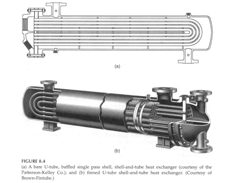
Tube Bundle Types Main objectives in design are to accommodate thermal expansion and allow easy cleaning (or to provide the least expensive construction) U-tube configuration (Fig. 8.4) –allows independent expansion of tubes and shell (unlimited thermal expansion) –only one tube sheet is needed (least expensive construction) –tube-side cannot be mechanically cleaned –even number of tube passes –individual tubes cannot be replaced (except those in the outer row)
 –allows independent expansion of tubes and shell (unlimited thermal expansion) –only one tube sheet is needed (least expensive construction) –tube-side cannot be mechanically cleaned –even number of tube passes –individual tubes cannot be replaced (except those in the outer row).")
10
Tube Bundle Types (continued) Fixed tube sheet configuration (Fig. 8.5) –allows mechanical cleaning of inside of tubes but not outside because shell is welded to the tube sheets –low-cost –limited thermal expansion –individual tubes replaceable Pull-through floating head (Fig. 8.6) –allows the tube sheet to float – move with thermal expansion –the tube bundle can be removed easily for cleaning – suitable for heavily fouling applications
 –allows mechanical cleaning of inside of tubes but not outside because shell is welded to the tube sheets –low-cost –limited thermal expansion –individual tubes replaceable Pull-through floating head (Fig. 8.6) –allows the tube sheet to float – move with thermal expansion –the tube bundle can be removed easily for cleaning – suitable for heavily fouling applications.")
13
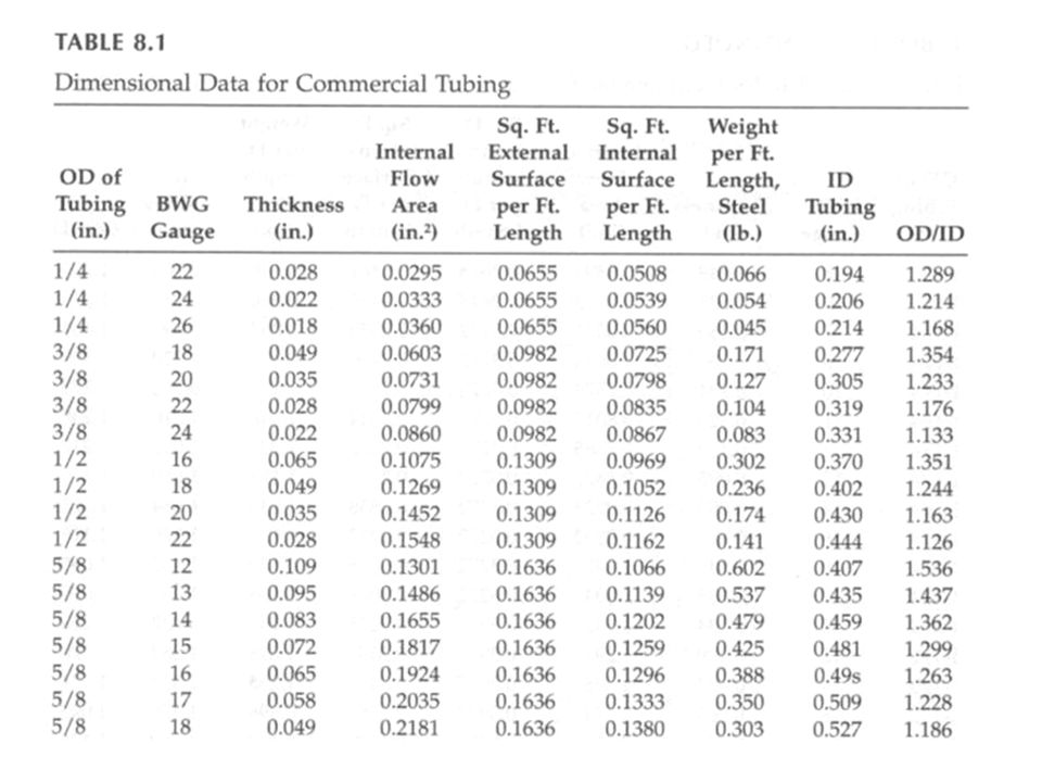
Tubes and Tube Passes Multiple units are used in series when E-shell and F-shell are not used (only they result in pure counterflow) or when the unit cannot deliver the desired temperatures A large number of tube passes are used to increase fluid velocity and heat transfer coefficient, and to minimize fouling Tube wall thickness is standardized in terms of the Birmingham Wire Gauge (BWG) of the tube (Tables 8.1 & 8.2) Small tube diameters for larger area/volume ratios, but limited for in-tube cleaning Larger tube diameters suitable for condensers and boilers Fins used on the outside of tubes when low heat transfer coefficient fluid is present on the shell-side Longer tubes → fewer tubes, fewer holes drilled, smaller shell diameter, lower cost. However limitations due to several factors result in 1/5 – 1/15 shell-diameter-to-tube-length ratio

16
Tube Layout Angle between the tubes 30 o results in greatest tube density, most common P T /d o is between 1.25 and 1.50 Maximum number of tubes that can be accommodated within a shell under specified conditions given in Table 8.3

18
Baffle Type and Geometry Baffles support the tubes for structural rigidity, thus prevent tube vibration and sagging They also divert the flow across the tube bundle to obtain a higher heat transfer coefficient Baffles can be transverse or longitudinal Transverse baffles are plate type or rod type Plate baffles –single and double segmental most common –baffle spacing is critical (optimum between 0.4 and 0.6 of the shell diameter) –triple and no-tubes-in-window segmental baffles for low pressure drop applications
 –triple and no-tubes-in-window segmental baffles for low pressure drop applications")
19
Figure 8.8 Plate Baffle Types

20
Figure 8.8 Plate Baffle Types (continued)
")
22
Allocation of Streams Selection of which fluid flows through the tubes and which fluid flows through the shell. In general, the following are considered and a trade-off is made between choices: –More seriously fouling fluid flows through the tubes (easier to clean). –High pressure fluid flows through the tubes (small diameter). –Corrosive fluid flows through the tubes, otherwise both shell and tube will be corroded. Cheaper to provide special alloy tubes than shell. –The fluid with the lower heat transfer coefficient flows through the shell, can have outside finned tubes. –The fluid with the lower mass flow rate flows through the shell, turbulent flow is obtained at lower Re on the shell side.
. –High pressure fluid flows through the tubes (small diameter). –Corrosive fluid flows through the tubes, otherwise both shell and tube will be corroded. Cheaper to provide special alloy tubes than shell. –The fluid with the lower heat transfer coefficient flows through the shell, can have outside finned tubes. –The fluid with the lower mass flow rate flows through the shell, turbulent flow is obtained at lower Re on the shell side..")
Similar presentations


>")


