Download presentation
Presentation is loading. Please wait.

1
P M V Subbarao Professor Mechanical Engineering Department I I T Delhi
Plate Heat Exchangers P M V Subbarao Professor Mechanical Engineering Department I I T Delhi Creators of Turbulent Flows at Low Reynolds Numbers…. Overall heat transfer coefficients (U) for plate type exchangers are three to four times those of shell and tube units ……
 for plate type exchangers are three to four times those of shell and tube units ……")
2
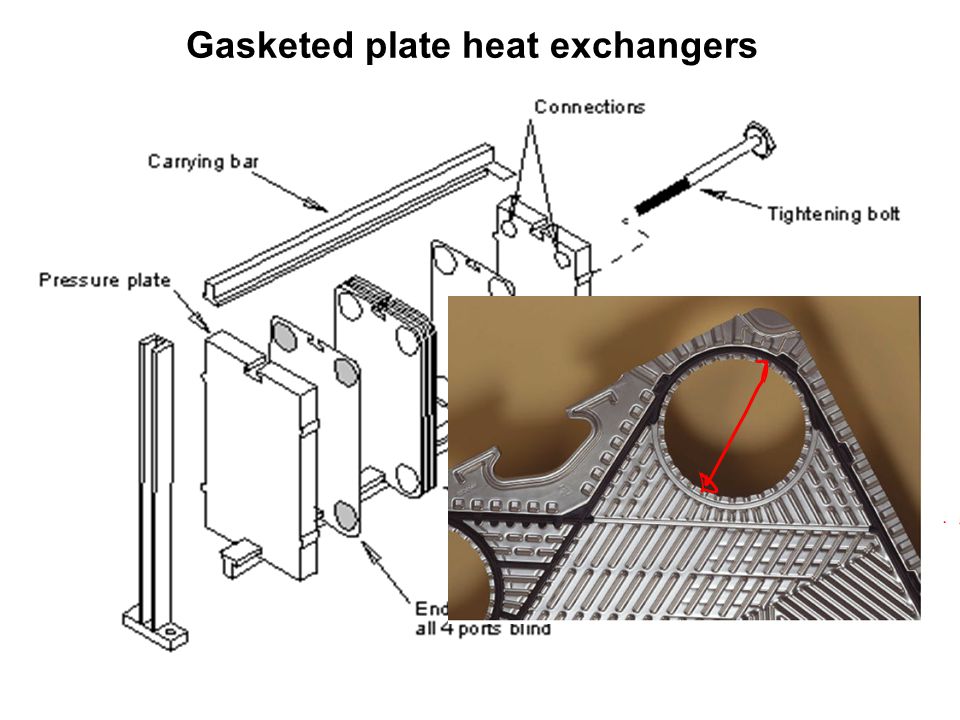
Plate heat exchangers The heat transfer surface consists of a number of thin corrugated plates pressed out of a high grade metal. The pressed pattern on each plate surface induces turbulence and minimises stagnant areas and fouling. Unlike shell and tube heat exchangers, which can be custom-built to meet almost any capacity and operating conditions, the plates for plate and frame heat exchangers are mass-produced using expensive dies and presses. All plate and frame heat exchangers are made with what may appear to be a limited range of plate designs.

3
Hot and Clod Flows through Plate Heat Exchangers

4
Hot and Clod Flows through Plate Heat Exchangers

5
Performance of Plate HXs
Superior thermal performance is the hallmark of plate heat exchangers. Compared to shell-and-tube units, plate heat exchangers offer overall heat transfer coefficients 3 to 4 times higher. These values, typically 4000 to 7000 W/m2 °C (clean), result in very compact equipment. This high performance also allows the specification of very small approach temperature (as low as 2 to 3°C) which is sometimes useful in geothermal applications. This high thermal performance does come at the expense of a somewhat higher pressure drop. Selection of a plate heat exchanger is a trade-off between U-value (which influences surface area and hence, capital cost) and pressure drop (which influences pump head and hence, operating cost). Increasing U-value comes at the expense of increasing pressure drop.
, result in very compact equipment. This high performance also allows the specification of very small approach temperature (as low as 2 to 3°C) which is sometimes useful in geothermal applications. This high thermal performance does come at the expense of a somewhat higher pressure drop. Selection of a plate heat exchanger is a trade-off between U-value (which influences surface area and hence, capital cost) and pressure drop (which influences pump head and hence, operating cost). Increasing U-value comes at the expense of increasing pressure drop.")
6
Classification of Plate HXs
Gasketed plate heat exchangers (plate and frame heat exchangers) Brazed plate heat exchangers Welded plate heat exchangers
 Brazed plate heat exchangers. Welded plate heat exchangers.")
7
Gasketed plate heat exchangers
8
The Characteristic Parameter
Thermal length is a dimensionless number that allows the design engineer to relate the performance characteristics of a channel geometry to those of a duty requirement. Thermal length (Θ) is the relationship between temperature difference DT on one fluid side and LMTD. The thermal length of a channel describes the ability of the channel to affect a temperature change based on the log mean temperature difference (LMTD). The thermal length of a channel is a function of the channel hydraulic diameter, plate length, and the angle of the corrugations, along with the physical properties of the process fluids and available pressure drop. To properly design a PHE, the thermal length required by the duty must be matched with that achievable by the selected channel geometry.
 is the relationship between temperature difference DT on one fluid side and LMTD. The thermal length of a channel describes the ability of the channel to affect a temperature change based on the log mean temperature difference (LMTD). The thermal length of a channel is a function of the channel hydraulic diameter, plate length, and the angle of the corrugations, along with the physical properties of the process fluids and available pressure drop. To properly design a PHE, the thermal length required by the duty must be matched with that achievable by the selected channel geometry.")
9
Central Idea A Plate HX is said to be Optimally Sized, if the thermal length required by the duty can match the characteristic of the channel, by utilizing all the available pressure drop with no over-dimensioning, for any chosen channel geometry.

10
Controlled Designs Thermally Controlled Designs:
If the design exceeds the allowable pressure drop for a given thermal duty. More plates be added and pressure drop is reduced by lowering the velocity. Such a design is termed thermally controlled. Hydraulically Controlled Designs: If the design pressure drop is than the allowable pressure drop. This results in a greater temperature change across the plate than required, or over-dimensioning. Few plates be removed and pressure drop is increased by increasing the velocity. Such a design is termed pressure drop controlled.

11
An Economic Design To have the most economical and efficient exchanger it is critical to choose, for each fluid, a channel geometry that matches the thermal length requirement of each fluid. Since thermal length achievable by a channel depends on the physical properties of the fluid, correction factors must be considered when the fluid’s physical properties differ from those for standard fluid (water

12
Design & Analysis of Plate HXs
Unlike tubular heat exchangers for which design data and methods are easily available, a plate heat exchanger design continues to be proprietary in nature. Manufacturers have developed their own computerized design procedures applicable to the exchangers marketed by them. Manufacturers of plate heat exchangers have, until recently, been criticised for not publishing their heat transfer and pressure loss correlations. Information which was published usually related to only one plate model or was of a generalized nature. The plates are mass-produced but the design of each plate pattern requires considerable research and investment, plus sound technical and commercial judgment, to achieve market success. As the market is highly competitive the manufacturer’s attitude is not unreasonable. The Chevron plate is the most common type in use today. The correlation enables a thermal design engineer to calculate heat transfer and pressure drop for a variety of Chevron plates.

13
STANDARD PLATE HEAT EXCHANGERS
Today’s conventional heat transfer plate designs are classified as chevron or herringbone type, with the corrugations forming a series of patterns. Each plate size is pressed with two different chevron angles, the low theta plate and high theta plate, and have acute and obtuse apex angles, respectively.

14
Plates Inlet / outlet Media 2 Inlet / outlet Media 1 Distribution area
Fully supported gasket groove Heat transfer area Distribution area Inlet / outlet Media 2 Inlet / outlet Media 1 engineering-resource.com

16
Conventional heat transfer plates and channel combinations.

18
PLATE GEOMETRY Chevron Angle: This important factor, usually termed b, is shown in Figure, the usual range of b being 25°-65°. Effective Plate Length : The corrugations increase the flat or projected plate area, the extent depending on the corrugation pitch and depth. To express the increase of the developed length, in relation to the projected length, an enlargement factor f is used. The enlargement factor varies between 1.1 and 1.25, with 1.17 being a typical average.
![]()
19
The value of f is also expressed as the ratio of the actual effective area as specified by the manufacturer, A1, to the projected plate area : A1p

20
Lp and Lw can be estimated from the port distance Lv and Lhand port diameter Dp as:

Similar presentations


