Download presentation
Presentation is loading. Please wait.

1
Intel MP

2
80386 (32-bit microprocessor)
Designed to overcome the limits of its predecessor while maintaining the software compatibility with the 8086 & earlier processors • Features: – 32 bit ALU – Segments can be as large as 4Gbytes – Total no. of segments possible: 16, 384 – Virtual address space is 16,384 X 4 = 64Tbytes of physical memory

3
FEATURES OF 80386: Two versions of are commonly available: 1) 80386DX 2)80386SX 80386DX SX 32 bit address bus ) 24 bit address bus 32bit data bus bit data bus Packaged in 132 pin ceramic ) 100 pin flat pin grid array(PGA) package 3) Address 4GB of memory ) 16 MB of memory
 24 bit address bus 32bit data bus 16 bit data bus. Packaged in 132 pin ceramic 2) 100 pin flat. pin grid array(PGA) package. 3) Address 4GB of memory 3) 16 MB of. memory.")
9
Real operating mode The has eight 32 - bit general purpose registers which may be used as either 8 bit or 16 bit registers. A 32 - bit register known as an extended register, is represented by the register name with prefix E. Example : A 32 bit register corresponding to AX is EAX, similarly BX is EBX etc. The 16 bit registers BP, SP, SI and DI in 8086 are now available with their extended size of 32 bit and are names as EBP,ESP,ESI and EDI. AX represents the lower 16 bit of the 32 bit register EAX. BP, SP, SI, DI represents the lower 16 bit of their 32 bit counterparts, and can be used as independent 16 bit registers.

10
Real operating mode (cont..)
The six segment registers available in are CS, SS, DS, ES, FS and GS. The CS and SS are the code and the stack segment registers respectively, while DS, ES, FS, GS are 4 data segment registers. A 32-bit instruction pointer The address range of 386 real mode is limited to 1Mbyte, so address lines A20-A31 are normally all low. The interrupt vector table of has been allocated 1Kbyte space starting from 00000H to 003FFH.

11
Real operating mode (cont..)
Debug register Intel has provide a set of 8 debug registers for hardware debugging. Out of these eight registers DR0 to DR7, two registers DR4 and DR5 are Intel reserved. The initial four registers DR0 to DR3 store four program controllable breakpoint addresses, while DR6 and DR7 respectively hold breakpoint status and breakpoint control information. Flag register 32-bit EFLAGS register

12
Control registers(CR0-CR3)
The lower 16-bits of CR0 correspond to the machine status word(MSW) of the As with an 80286, a 386 is switched to protected mode operation by setting the LSB of this register to a 1. Register CR1 is reserved by Intel Registers CR2 and CR3 are used for paged mode function.
 of the As with an 80286, a 386 is switched to protected mode operation by setting the LSB of this register to a 1. Register CR1 is reserved by Intel. Registers CR2 and CR3 are used for paged mode function.")
13
Protected Mode of 80386: •All the capabilities of are available for utilization in its protected mode of operation. •The in protected mode support all the software written for and 8086 to be executed under the control of memory management and protection abilities of •The protected mode allows the use of additional instruction, addressing modes and capabilities of

14
•The Memory management unit consists of
Segmentation unit and Paging unit. •Segmentation unit allows the use of two address components, viz. segment and offset for relocability and sharing of code and data. •Segmentation unit allows segments of size 4Gbytes at max. •The Paging unit organizes the physical memory in terms of pages of 4kbytes size each. •Paging unit works under the control of the segmentation unit, i.e. each segment is further divided into pages. The virtual memory is also organizes in terms of segments and pages by the memory management unit.

15
•Segment Descriptor Registers: This registers are not available for programmers, rather they are internally used to store the descriptor information, like attributes, limit and base addresses of segments. •The six segment registers have corresponding six 73 bit descriptor registers. Each of them contains 32 bit base address, 32 bit base limit and 9 bit attributes. These are automatically loaded when the corresponding segments are loaded with selectors. •Control Registers: The has three 32 bit control registers CR0, CR2 and CR3 to hold global machine status independent of the executed task. Load and store instructions are available to access these registers. •System Address Registers: Four special registers are defined to refer to the descriptor tables supported by

16
ADDRESSING IN PROTECTED MODE: In this mode, the contents of segment registers are used as selectors to address descriptors which contain the segment limit, base address and access rights byte of the segment. •The effective address (offset) is added with segment base address to calculate linear address. This linear address is further used as physical address, if the paging unit is disabled, otherwise the paging unit converts the linear address into physical address. •The paging unit is a memory management unit enabled only in protected mode. The paging mechanism allows handling of large segments of memory in terms of pages of 4Kbyte size.
 is added with segment base address to calculate linear address. This linear address is further used as physical address, if the paging unit is disabled, otherwise the paging unit converts the linear address into physical address. •The paging unit is a memory management unit enabled only in protected mode. The paging mechanism allows handling of large segments of memory in terms of pages of 4Kbyte size.")
17
•The paging unit operates under the control of segmentation unit
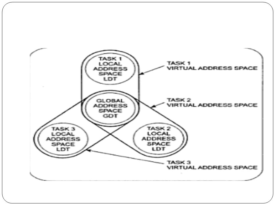
•The paging unit operates under the control of segmentation unit. The paging unit if enabled converts linear addresses into physical address, in protected mode. Segmentation: •Descriptor tables: These descriptor tables and registers are manipulated by the operating system to ensure the correct operation of the processor, and hence the correct execution of the program. •Two types of the descriptor tables are listed as follows: •GLOBAL DESCRIPTOR TABLE ( GDT ) •LOCAL DESCRIPTOR TABLE ( LDT )
 •LOCAL DESCRIPTOR TABLE ( LDT )")
18
•Descriptors: The descriptors have a 20-bit segment limit and 32-bit segment address. The descriptor of are 8-byte quantities access right or attribute bits along with the base and limit of the segments.

19
Segmentation and virtual memory

21
386 segment privilege levels protection

Similar presentations


 An Introduction to the 80x86 Microprocessor Family Objectives: The different addressing modes and instruction types available The usefulness.>")


 80386DX>")

 By Dr. Syed Noman.>")


>")


