Download presentation
Presentation is loading. Please wait.

1
Measuring Devices

2
Electromagnetic Deflection
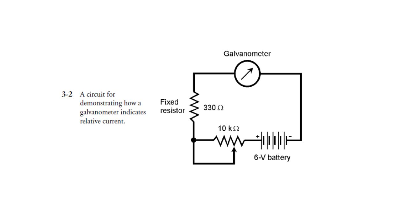
Early experimenters with electricity and magnetism noticed that an electric current produces a magnetic field. When a magnetic compass is placed near a wire carrying a direct electric current, the compass doesn’t point toward magnetic north. The needle is displaced. The extent of the displacement depends on how close the compass is brought to the wire, and also on how much current the wire is carrying. When this effect was first observed, scientists tried different arrangements to see how much the compass needle could be displaced, and how small a current could be detected. An attempt was made to obtain the greatest possible current- detecting sensitivity. Wrapping the wire in a coil around the compass resulted in a device that could indicate a tiny electric current (Fig. 3-1). This effect is known as galvanism, and the meter so devised was called a galvanometer. Once this device was made, the scientists saw that the extent of the needle displacement increased with increasing current. Then, the only challenge was to calibrate the galvanometer somehow, and to find a standard so a universal meter could be engineered. You can make your own galvanometer. Buy a cheap compass, about 2 feet of insulated bell wire, and a 6-volt lantern battery. Set it up as shown in Fig Wrap the wire around the compass four or five times, and align the compass so that the needle points along the wire turns while the wire is disconnected from the battery. Connect one end of the wire to the negative (−) terminal of the battery. Touch the other end to the positive (+) terminal for a second or two, and watch the compass needle. Don’t leave the wire connected to the battery for any length of time unless you want to drain the battery in a hurry. You can buy a resistor and a potentiometer at a place like RadioShack, and set up an experiment that shows how galvanometers measure current. For a 6-V lantern battery, the fixed resistor should have a value of at least 330 Ω and should be rated for at least 1⁄ 4W. The potentiometer should have a maximum value of 10 kΩ. Connect the resistor and potentiometer in series between one end of the bell wire and one terminal of the battery, as shown in Fig The center contact of the potentiometer should be short-circuited to one of the end contacts, and the resulting two terminals used in the circuit. When you adjust the potentiometer, the compass needle should deflect more or less, depending on the current through the wire. Early experimenters calibrated their meters by referring to the degrees scale around the perimeter of the compass.
. This effect is known as galvanism, and the meter so devised was called a galvanometer. Once this device was made, the scientists saw that the extent of the needle displacement increased with increasing current. Then, the only challenge was to calibrate the galvanometer somehow, and to find a standard so a universal meter could be engineered. You can make your own galvanometer. Buy a cheap compass, about 2 feet of insulated bell wire, and a 6-volt lantern battery. Set it up as shown in Fig Wrap the wire around the compass four or five times, and align the compass so that the needle points along the wire turns while the wire is disconnected from the battery. Connect one end of the wire to the negative (−) terminal of the battery. Touch the other end to the positive (+) terminal for a second or two, and watch the compass needle. Don’t leave the wire connected to the battery for any length of time unless you want to drain the battery in a hurry. You can buy a resistor and a potentiometer at a place like RadioShack, and set up an experiment that shows how galvanometers measure current. For a 6-V lantern battery, the fixed resistor should have a value of at least 330 Ω and should be rated for at least 1⁄ 4W. The potentiometer should have a maximum value of 10 kΩ. Connect the resistor and potentiometer in series between one end of the bell wire and one terminal of the battery, as shown in Fig The center contact of the potentiometer should be short-circuited to one of the end contacts, and the resulting two terminals used in the circuit. When you adjust the potentiometer, the compass needle should deflect more or less, depending on the current through the wire. Early experimenters calibrated their meters by referring to the degrees scale around the perimeter of the compass.")
4
Electrostatic Deflection
Electric fields produce forces, just as magnetic fields do. You have noticed this when your hair feels like it’s standing on end in very dry or cold weather. You’ve heard that people’s hair really does stand straight out just before a lightning bolt hits nearby. (This is no myth!) The most common device for demonstrating electrostatic forces is the electroscope. It consists of two foil leaves, attached to a conducting rod, and placed in a sealed container so that air currents cannot move the foil leaves (Fig. 3-3). When a charged object is brought near, or touched to, the contact at the top of the rod, the leaves stand apart from each other. This is because the two leaves become charged with like electric poles—either an excess or a deficiency of electrons—and like poles always repel. The extent to which the leaves stand apart depends on the amount of electric charge. It is difficult to measure this deflection and correlate it with charge quantity; electroscopes do not make very good meters. But variations on this theme can be employed, so that electrostatic forces can operate against tension springs or magnets, and in this way, electrostatic meters can be made. An electrostatic meter can quantify alternating (or ac) electric charges as well as direct (or dc) charges. This gives electrostatic meters an advantage over electromagnetic meters such as the galvanometers. If you connect a source of ac to the coil of the galvanometer device in Fig. 3-1 or Fig. 3-2, the compass needle will not give a clear deflection; current in one direction pulls the meter needle one way, and current in the other direction pushes the needle the opposite way. But if a source of ac is connected to an electrostatic meter, the plates repel whether the charge is positive or negative at any given instant in time. Most electroscopes aren’t sensitive enough to show much deflection with ordinary 117-V utility ac. Don’t try connecting 117 V to an electroscope anyway. It can present an electrocution hazard if you bring it out to points where you can easily come into physical contact with it. An electrostatic meter has another property that is sometimes an advantage in electrical or electronic work. This is the fact that the device does not draw any current, except a tiny initial current needed to put a charge on the plates. Sometimes, an engineer or experimenter doesn’t want a measuring device to draw current, because this affects the behavior of the circuit under test. Galvanometers, by contrast, always need some current to produce an indication.
 The most common device for demonstrating electrostatic forces is the electroscope. It consists of two foil leaves, attached to a conducting rod, and placed in a sealed container so that air currents cannot move the foil leaves (Fig. 3-3). When a charged object is brought near, or touched to, the contact at the top of the rod, the leaves stand apart from each other. This is because the two leaves become charged with like electric poles—either an excess or a deficiency of electrons—and like poles always repel. The extent to which the leaves stand apart depends on the amount of electric charge. It is difficult to measure this deflection and correlate it with charge quantity; electroscopes do not make very good meters. But variations on this theme can be employed, so that electrostatic forces can operate against tension springs or magnets, and in this way, electrostatic meters can be made. An electrostatic meter can quantify alternating (or ac) electric charges as well as direct (or dc) charges. This gives electrostatic meters an advantage over electromagnetic meters such as the galvanometers. If you connect a source of ac to the coil of the galvanometer device in Fig. 3-1 or Fig. 3-2, the compass needle will not give a clear deflection; current in one direction pulls the meter needle one way, and current in the other direction pushes the needle the opposite way. But if a source of ac is connected to an electrostatic meter, the plates repel whether the charge is positive or negative at any given instant in time. Most electroscopes aren’t sensitive enough to show much deflection with ordinary 117-V utility ac. Don’t try connecting 117 V to an electroscope anyway. It can present an electrocution hazard if you bring it out to points where you can easily come into physical contact with it. An electrostatic meter has another property that is sometimes an advantage in electrical or electronic work. This is the fact that the device does not draw any current, except a tiny initial current needed to put a charge on the plates. Sometimes, an engineer or experimenter doesn’t want a measuring device to draw current, because this affects the behavior of the circuit under test. Galvanometers, by contrast, always need some current to produce an indication.")
6
If you have access to a laboratory electroscope, try charging it up with a glass rod that has been rubbed against a cloth. When the rod is pulled away from the electroscope, the foil leaves remain standing apart. The charge just sits there! If the electroscope drew any current, the leaves would fall back together again, just as the galvanometer compass needle returns to magnetic north the instant you take the wire from the battery.

7
Thermal Heating Another phenomenon, sometimes useful in the measurement of electric currents, is the fact that whenever current flows through a conductor having any resistance, that conductor is heated. All conductors have some resistance; none are perfect. The extent of this heating is proportional to the amount of current being carried by the wire. By choosing the right metal or alloy, and by making the wire a certain length and diameter, and by employing a sensitive thermometer, and by putting the entire assembly inside a thermally insulating package, a hot-wire meter can be made. The hot-wire meter can measure ac as well as dc, because the current-heating phenomenon does not depend on the direction of current flow. A variation of the hot-wire principle can be used to advantage by placing two different metals into contact with each other. If the right metals are chosen, the junction heats up when a current flows through it. This is called the thermocouple principle. As with the hot-wire meter, a thermometer can be used to measure the extent of the heating. But there is also another effect. A thermocouple, when it gets warm, generates dc. This dc can be measured with a galvanometer. This method is useful when it is necessary to have a fast meter response time. The hot-wire and thermocouple effects are sometimes used to measure ac at high frequencies, in the range of hundreds of kilohertz up to tens of gigahertz.

8
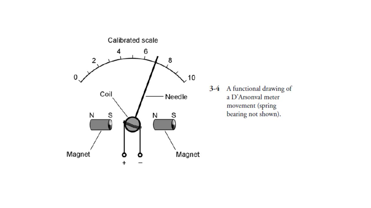
Ammeters A magnetic compass doesn’t make a very convenient meter. It has to be lying flat, and the coil has to be aligned with the compass needle when there is no current. But of course, electrical and electronic devices aren’t all oriented so as to be aligned with the north geomagnetic pole! But the external magnetic field doesn’t have to come from the earth. It can be provided by a permanent magnet near or inside the meter. This supplies a stronger magnetic force than does the earth’s magnetic field, and therefore makes it possible to make a meter that can detect much weaker currents. Such a meter can be turned in any direction, and its operation is not affected. The coil can be attached directly to the meter pointer, and suspended by means of a spring in the field of the magnet. This type of metering scheme, called the D’Arsonval movement, has been around since the earliest days of electricity, but it is still used in some metering devices today. The assembly is shown in Fig This is the basic principle of the ammeter. A variation of the D’Arsonval movement can be obtained by attaching the meter needle to a permanent magnet, and winding the coil in a fixed form around the magnet. Current in the coil produces a magnetic field, and this in turn generates a force if the coil and magnet are aligned correctly with respect to each other. This works all right, but the mass of the permanent magnet causes a slower needle response. This type of meter is also more prone to overshoot than the true D’Arsonval movement; the inertia of the magnet’s mass, once overcome by the magnetic force, causes the needle to fly past the actual point for the current reading, and then to wag back and forth a couple of times before coming to rest in the right place.

10
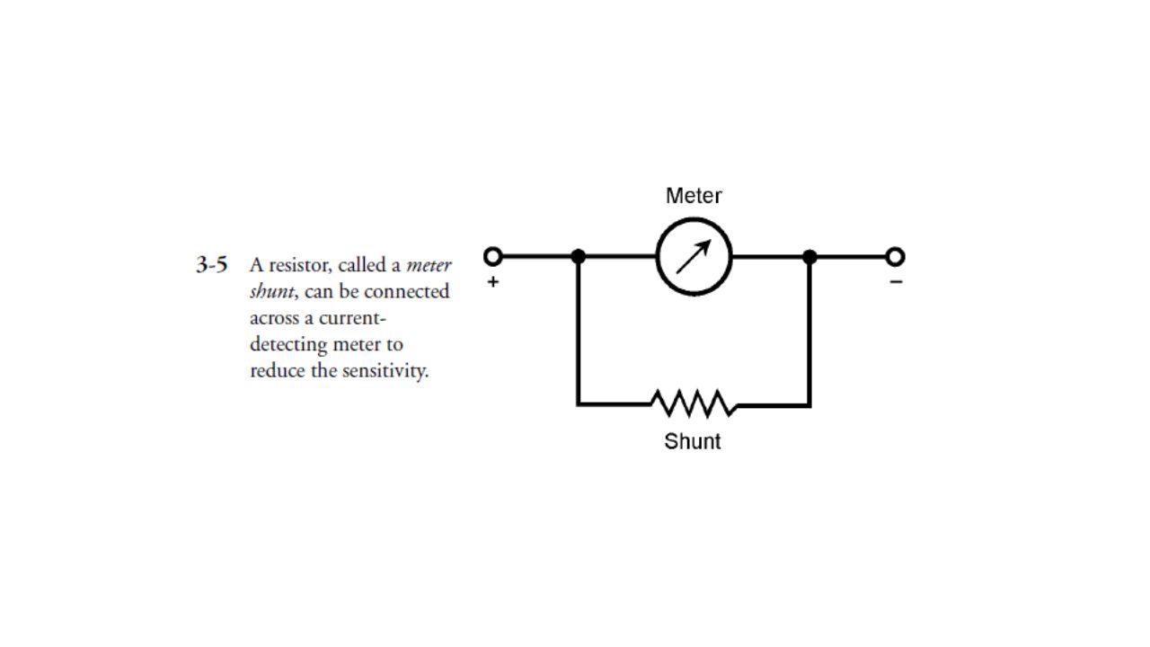
It is possible to use an electromagnet in place of the permanent magnet in the meter assembly. This electromagnet can be operated by the same current that flows in the coil attached to the meter needle. This gets rid of the need for a massive, permanent magnet inside the meter. It also eliminates the possibility that the meter sensitivity will change in case the strength of the permanent magnet deteriorates (such as might be caused by heat, or by severe mechanical vibration). The electromagnet can be either in series with, or in parallel with, the meter movement coil. The sensitivity of the D’Arsonval-type meter, and of similar designs, depends on several factors. First is the strength of the permanent magnet (if the meter uses a permanent magnet). Second is the number of turns in the coil. The stronger the magnet, and the larger the number of turns in the coil, the less current is needed in order to produce a given magnetic force. If the meter is of the electromagnet type, the combined number of coil turns affects the sensitivity. Remember that the strength of a magnetomotive force is given in terms of ampere-turns. For a given current (number of amperes), the force increases in direct proportion to the number of coil turns. The more force in a meter, the greater the needle deflection for a given amount of current, and the smaller the current necessary to cause a certain amount of needle movement. The most sensitive ammeters can detect currents of just a microampere or two. The amount of current for full-scale deflection (the needle goes all the way up without banging against the stop pin) can be as little as about 50 μA in commonly available meters. Sometimes, it is desirable to have an ammeter that will allow for a wide range of current measurements. The full-scale deflection of a meter assembly cannot easily be changed, because that would mean changing the number of coil turns and/or the strength of the magnet. But all ammeters have a certain amount of internal resistance. If a resistor, having the same internal resistance as the meter, is connected in parallel with the meter, the resistor will draw half the current. Then it will take twice the current through the assembly to deflect the meter to full scale, as compared with the meter alone. By choosing a resistor of just the right value, the full-scale deflection of an ammeter can be increased by a large factor, such as 10, or 100, or This resistor must be capable of carrying the current without burning up. It might have to draw practically all of the current flowing through the assembly, leaving the meter to carry only 1/10, or 1/100, or 1/1000 of the current. This is called a shunt resistance or meter shunt (Fig. 3-5). Meter shunts are used when it is necessary to measure very large currents, such as hundreds of amperes. They also allow microammeters or milliammeters to be used in a versatile multimeter, with many current ranges.
. The electromagnet can be either in series with, or in parallel with, the meter movement coil. The sensitivity of the D’Arsonval-type meter, and of similar designs, depends on several factors. First is the strength of the permanent magnet (if the meter uses a permanent magnet). Second is the number of turns in the coil. The stronger the magnet, and the larger the number of turns in the coil, the less current is needed in order to produce a given magnetic force. If the meter is of the electromagnet type, the combined number of coil turns affects the sensitivity. Remember that the strength of a magnetomotive force is given in terms of ampere-turns. For a given current (number of amperes), the force increases in direct proportion to the number of coil turns. The more force in a meter, the greater the needle deflection for a given amount of current, and the smaller the current necessary to cause a certain amount of needle movement. The most sensitive ammeters can detect currents of just a microampere or two. The amount of current for full-scale deflection (the needle goes all the way up without banging against the stop pin) can be as little as about 50 μA in commonly available meters. Sometimes, it is desirable to have an ammeter that will allow for a wide range of current measurements. The full-scale deflection of a meter assembly cannot easily be changed, because that would mean changing the number of coil turns and/or the strength of the magnet. But all ammeters have a certain amount of internal resistance. If a resistor, having the same internal resistance as the meter, is connected in parallel with the meter, the resistor will draw half the current. Then it will take twice the current through the assembly to deflect the meter to full scale, as compared with the meter alone. By choosing a resistor of just the right value, the full-scale deflection of an ammeter can be increased by a large factor, such as 10, or 100, or This resistor must be capable of carrying the current without burning up. It might have to draw practically all of the current flowing through the assembly, leaving the meter to carry only 1/10, or 1/100, or 1/1000 of the current. This is called a shunt resistance or meter shunt (Fig. 3-5). Meter shunts are used when it is necessary to measure very large currents, such as hundreds of amperes. They also allow microammeters or milliammeters to be used in a versatile multimeter, with many current ranges.")
12
Voltmeters Current, as we have seen, consists of a flow of charge carriers. Voltage, or electromotive force (EMF), or potential difference, is the “pressure” that makes current possible. Given a circuit whose resistance is constant, the current that flows in the circuit is directly proportional to the voltage placed across it. Early electrical experimenters recognized that an ammeter could be used to measure voltage, because an ammeter is a form of constant-resistance circuit. If you connect an ammeter directly across a source of voltage such as a battery, the meter needle deflects. In fact, a milliammeter needle will probably be “pinned” if you do this with it, and a microammeter might well be wrecked by the force of the needle striking the pin at the top of the scale. For this reason, you should never connect milliammeters or microammeters directly across voltage sources. An ammeter, perhaps with a range of 0 to 10 A, might not deflect to full scale if it is placed across a battery, but it’s still a bad idea to do this, because it will rapidly drain the battery. Some batteries, such as automotive lead-acid cells, can explode under these conditions. Ammeters have low internal resistance. They are designed that way deliberately. They are meant to be connected in series with other parts of a circuit, not right across a power supply. But if you place a large resistor in series with an ammeter, and then connect the ammeter across a battery or other type of power supply, you no longer have a short circuit. The ammeter will give an indication that is directly proportional to the voltage of the supply. The smaller the full-scale reading of the ammeter, the larger the resistance that is needed to get a meaningful indication on the meter. Using a microammeter and a very large value of resistance in series, a voltmeter can be devised that will draw only a little current from the source. A voltmeter can be made to have various ranges for the full-scale reading, by switching different values of resistance in series with the microammeter (Fig. 3-6). The internal resistance of the meter is large because the values of the resistors are large. The greater the supply voltage, the larger the internal resistance of the meter, because the necessary series resistance increases as the voltage increases. A voltmeter should have high internal resistance, and the higher the better! The reason for this is that you don’t want the meter to draw much current from the power source. This current should go, as much as possible, toward operating whatever circuit is hooked up to the power supply, and not into getting a reading of the voltage. Also, you might not want, or need, to have the voltmeter constantly connected in the circuit; you might need the voltmeter for testing many different circuits. You don’t want the behavior of a circuit to be affected the instant you connect the voltmeter to the supply. The less current a voltmeter draws, the less it affects the behavior of anything that is working from the power supply.
, or potential difference, is the pressure that makes current possible. Given a circuit whose resistance is constant, the current that flows in the circuit is directly proportional to the voltage placed across it. Early electrical experimenters recognized that an ammeter could be used to measure voltage, because an ammeter is a form of constant-resistance circuit. If you connect an ammeter directly across a source of voltage such as a battery, the meter needle deflects. In fact, a milliammeter needle will probably be pinned if you do this with it, and a microammeter might well be wrecked by the force of the needle striking the pin at the top of the scale. For this reason, you should never connect milliammeters or microammeters directly across voltage sources. An ammeter, perhaps with a range of 0 to 10 A, might not deflect to full scale if it is placed across a battery, but it’s still a bad idea to do this, because it will rapidly drain the battery. Some batteries, such as automotive lead-acid cells, can explode under these conditions. Ammeters have low internal resistance. They are designed that way deliberately. They are meant to be connected in series with other parts of a circuit, not right across a power supply. But if you place a large resistor in series with an ammeter, and then connect the ammeter across a battery or other type of power supply, you no longer have a short circuit. The ammeter will give an indication that is directly proportional to the voltage of the supply. The smaller the full-scale reading of the ammeter, the larger the resistance that is needed to get a meaningful indication on the meter. Using a microammeter and a very large value of resistance in series, a voltmeter can be devised that will draw only a little current from the source. A voltmeter can be made to have various ranges for the full-scale reading, by switching different values of resistance in series with the microammeter (Fig. 3-6). The internal resistance of the meter is large because the values of the resistors are large. The greater the supply voltage, the larger the internal resistance of the meter, because the necessary series resistance increases as the voltage increases. A voltmeter should have high internal resistance, and the higher the better! The reason for this is that you don’t want the meter to draw much current from the power source. This current should go, as much as possible, toward operating whatever circuit is hooked up to the power supply, and not into getting a reading of the voltage. Also, you might not want, or need, to have the voltmeter constantly connected in the circuit; you might need the voltmeter for testing many different circuits. You don’t want the behavior of a circuit to be affected the instant you connect the voltmeter to the supply. The less current a voltmeter draws, the less it affects the behavior of anything that is working from the power supply.")
14
A completely different type of voltmeter uses the effect of electrostatic deflection, rather than electromagnetic deflection. Remember that electric fields produce forces, just as do magnetic fields. Therefore, a pair of plates attract or repel each other if they are charged. The electrostatic voltmeter takes advantage of the attractive force between two plates having opposite electric charge, or having a large potential difference. Figure 3-7 is a simplified drawing of the mechanics of an electrostatic voltmeter. It draws almost no current from the power supply. The only thing between the plates is air, and air is a nearly perfect insulator. The electrostatic meter can indicate ac voltage as well as dc voltage. The construction tends to be fragile, however, and mechanical vibration can influence the reading.

16
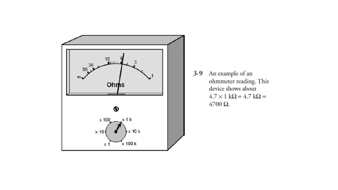
Ohmmeters If all other factors are held constant, the current through a circuit depends on the resistance. This provides us with a means for measuring resistance. An ohmmeter can be constructed by placing a milliammeter or microammeter in series with a set of fixed, switchable resistances and a battery that provides a known, constant voltage (Fig. 3-8). By selecting the resistances appropriately, the meter gives indications in ohms over any desired range. The zero point on the milliammeter or microammeter is assigned the value of infinity ohms, meaning a perfect insulator. The full-scale value is set at a certain minimum, such as 1 Ω, 100 Ω, 1 kΩ, or 10 kΩ. An ohmmeter must be calibrated at the factory where it is made, or in an electronics lab. A slight error in the values of the series resistors can cause gigantic errors in measured resistance. Therefore, precise tolerances are needed for these resistors. That means their values must actually be what the manufacturer claims they are, to within a fraction of 1 percent if possible. It is also necessary that the battery provide exactly the right voltage. The scale of an ohmmeter is nonlinear. That means the graduations are not of the same width everywhere on the meter scale. The graduations tend to be squashed together toward the infinity end of the scale. Because of this, it is difficult to interpolate for high values of resistance unless the appropriate meter range is selected. Engineers and technicians usually connect an ohmmeter in a circuit with the meter set for the highest resistance range first. Then they switch the range down until the meter needle is in a part of the scale that is easy to read. Finally, the reading is taken, and is multiplied (or divided) by the appropriate amount as indicated on the range switch. Figure 3-9 shows an ohmmeter reading. The meter itself indicates approximately 4.7, but the range switch says 1 kΩ. This indicates a resistance of about 4.7 kΩ, or 4700 Ω. Ohmmeters give inaccurate readings if there is a voltage between the points where the meter is connected. This is because such a voltage either adds to, or subtracts from, the ohmmeter’s own battery voltage. Sometimes, in this type of situation, an ohmmeter might tell you that a circuit has “more than infinity” ohms! The needle will hit the pin at the left end of the scale. Therefore, when using an ohmmeter to measure resistance, you must always be sure that there is no voltage between the points under test. The best way to do this is to switch off the equipment in question.
. By selecting the resistances appropriately, the meter gives indications in ohms over any desired range. The zero point on the milliammeter or microammeter is assigned the value of infinity ohms, meaning a perfect insulator. The full-scale value is set at a certain minimum, such as 1 Ω, 100 Ω, 1 kΩ, or 10 kΩ. An ohmmeter must be calibrated at the factory where it is made, or in an electronics lab. A slight error in the values of the series resistors can cause gigantic errors in measured resistance. Therefore, precise tolerances are needed for these resistors. That means their values must actually be what the manufacturer claims they are, to within a fraction of 1 percent if possible. It is also necessary that the battery provide exactly the right voltage. The scale of an ohmmeter is nonlinear. That means the graduations are not of the same width everywhere on the meter scale. The graduations tend to be squashed together toward the infinity end of the scale. Because of this, it is difficult to interpolate for high values of resistance unless the appropriate meter range is selected. Engineers and technicians usually connect an ohmmeter in a circuit with the meter set for the highest resistance range first. Then they switch the range down until the meter needle is in a part of the scale that is easy to read. Finally, the reading is taken, and is multiplied (or divided) by the appropriate amount as indicated on the range switch. Figure 3-9 shows an ohmmeter reading. The meter itself indicates approximately 4.7, but the range switch says 1 kΩ. This indicates a resistance of about 4.7 kΩ, or 4700 Ω. Ohmmeters give inaccurate readings if there is a voltage between the points where the meter is connected. This is because such a voltage either adds to, or subtracts from, the ohmmeter’s own battery voltage. Sometimes, in this type of situation, an ohmmeter might tell you that a circuit has more than infinity ohms! The needle will hit the pin at the left end of the scale. Therefore, when using an ohmmeter to measure resistance, you must always be sure that there is no voltage between the points under test. The best way to do this is to switch off the equipment in question.")
19
Multimeters In the electronics lab, a common piece of test equipment is the multimeter, in which different kinds of meters are combined into a single unit. The volt-ohm- milliammeter (VOM) is the most often used. As its name implies, it combines voltage, resistance, and current measuring capabilities. You should not have trouble envisioning how a single milliammeter can be used for measuring voltage, current, and resistance. The preceding discussions for measurements of these quantities have all included methods in which a current meter can be used to measure the intended quantity. Commercially available multimeters have certain limits in the values they can measure. The maximum voltage is around 1000 V. The measurement of larger voltages requires special probes and heavily insulated wires, as well as other safety precautions. The maximum current that a common VOM can measure is about 1 A. The maximum measurable resistance is on the order of several megohms or tens of megohms. The lower limit of resistance indication is around 0.1 to 1 Ω.
 is the most often used. As its name implies, it combines voltage, resistance, and current measuring capabilities. You should not have trouble envisioning how a single milliammeter can be used for measuring voltage, current, and resistance. The preceding discussions for measurements of these quantities have all included methods in which a current meter can be used to measure the intended quantity. Commercially available multimeters have certain limits in the values they can measure. The maximum voltage is around 1000 V. The measurement of larger voltages requires special probes and heavily insulated wires, as well as other safety precautions. The maximum current that a common VOM can measure is about 1 A. The maximum measurable resistance is on the order of several megohms or tens of megohms. The lower limit of resistance indication is around 0.1 to 1 Ω.")
20
FET Voltmeters A good voltmeter disturbs the circuit under test as little as possible, and this requires that the meter have high internal resistance. Besides the electrostatic-type voltmeter, there is another way to get high internal resistance. This is to sample a tiny current, far too small for any meter to directly indicate, and then amplify this current so a conventional milliammeter or microammeter can display it. When a minuscule current is drawn from a circuit, the equivalent resistance is always extremely high. The most effective way to accomplish voltage amplification, while making sure that the current drawn is exceedingly small, is to use a field- effect transistor, or FET. (Don’t worry about how such amplifiers work right now; you’ll learn all about that later in this book.) A voltmeter that uses a FET voltage amplifier to minimize the current drain is known as a FET voltmeter (FETVM). It has extremely high input resistance, along with good sensitivity and amplification.
 A voltmeter that uses a FET voltage amplifier to minimize the current drain is known as a FET voltmeter (FETVM). It has extremely high input resistance, along with good sensitivity and amplification.")
21
Wattmeters The measurement of electrical power requires that voltage and current both be measured simultaneously. Remember that in a dc circuit, the power (P ) in watts is the product of the voltage (E ) in volts and the current (I ) in amperes. That is, P = EI. In fact, watts are sometimes called volt-amperes in dc circuits. Do you think you can connect a voltmeter in parallel with a circuit, thereby getting a reading of the voltage across it, and also hook up an ammeter in series to get a reading of the current through the circuit, and then multiply volts times amperes to get watts consumed by the circuit? Well, you can. For most dc circuits, this is an excellent way to measure power, as shown in Fig Sometimes, it’s simpler yet. In many cases, the voltage from the power supply is constant and predictable. Utility power is a good example. The effective voltage is always very close to 117 V. Although it’s ac, and not dc, power in most utility circuits can be measured in the same way as power is measured in dc circuits: by means of an ammeter connected in series with the circuit, and calibrated so that the multiplication (times 117) has already been done. Then, rather than 1 A, the meter will show a reading of 117 W, because P = EI = 117 × 1 = 117 W. If the meter reading is 300 W, the current is I = P/E = 300/117 = 2.56 A. An electric iron might consume 1000 W, or a current of 1000/117 = 8.55 A. A large heating unit might gobble up 2000 W, requiring a current of 2000/117 = 17.1 A. You should not be surprised if this blows a fuse or trips a circuit breaker, because these devices are often rated for 15 A. Specialized wattmeters are necessary for the measurement of radio-frequency (RF) power, or for peak audio power in a high-fidelity amplifier, or for certain other specialized applications. But almost all of these meters, whatever the associated circuitry, use simple ammeters, milliammeters, or microammeters as their indicating devices.
 in watts is the product of the voltage (E ) in volts and the current (I ) in amperes. That is, P = EI. In fact, watts are sometimes called volt-amperes in dc circuits. Do you think you can connect a voltmeter in parallel with a circuit, thereby getting a reading of the voltage across it, and also hook up an ammeter in series to get a reading of the current through the circuit, and then multiply volts times amperes to get watts consumed by the circuit Well, you can. For most dc circuits, this is an excellent way to measure power, as shown in Fig Sometimes, it’s simpler yet. In many cases, the voltage from the power supply is constant and predictable. Utility power is a good example. The effective voltage is always very close to 117 V. Although it’s ac, and not dc, power in most utility circuits can be measured in the same way as power is measured in dc circuits: by means of an ammeter connected in series with the circuit, and calibrated so that the multiplication (times 117) has already been done. Then, rather than 1 A, the meter will show a reading of 117 W, because P = EI = 117 × 1 = 117 W. If the meter reading is 300 W, the current is I = P/E = 300/117 = 2.56 A. An electric iron might consume 1000 W, or a current of 1000/117 = 8.55 A. A large heating unit might gobble up 2000 W, requiring a current of 2000/117 = 17.1 A. You should not be surprised if this blows a fuse or trips a circuit breaker, because these devices are often rated for 15 A. Specialized wattmeters are necessary for the measurement of radio-frequency (RF) power, or for peak audio power in a high-fidelity amplifier, or for certain other specialized applications. But almost all of these meters, whatever the associated circuitry, use simple ammeters, milliammeters, or microammeters as their indicating devices.")
24
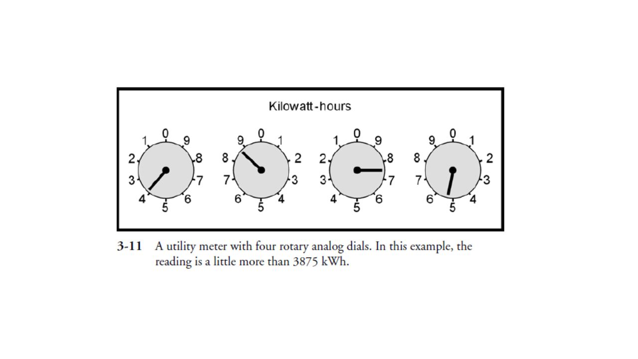
Watt-Hour Meters Electrical energy, as you now know, is measured in watt-hours or kilowatt-hours (kWh). Not surprisingly, a metering device that indicates energy in these units is called a watt-hour meter or a kilowatt-hour meter. The most often used means of measuring electrical energy is by using a small electric motor, the speed of which depends on the current, and thereby on the power at a constant voltage. The number of turns of the motor shaft, in a given length of time, is directly proportional to the number of kilowatt-hours consumed. The motor is placed at the point where the utility wires enter the building. This is usually at a point where the voltage is 234 V. At this point the circuit is split into some circuits with 234 V (for heavy-duty appliances such as the oven, washer, and dryer) and general household circuits at 117 V (for smaller appliances such as lamps, clock radios, and television sets). If you’ve observed a kilowatt-hour meter, you have seen a disk spinning, sometimes fast, other times slowly. Its speed depends on the power being used at any given time. The total number of turns of this little disk, every month, determines the size of the bill you will get, as a function also, of course, of the cost per kilowatt-hour. Kilowatt-hour meters count the number of disk turns by means of geared rotary drums or pointers. The drum-type meter gives a direct digital readout. The pointer type has several scales calibrated from 0 to 9 in circles, some going clockwise and others going counterclockwise. Reading a pointer-type utility meter is a little tricky, because you must think in whatever direction (clockwise or counterclockwise) the scale goes. An example of a pointer-type utility meter is illustrated in Fig Read from left to right. For each meter scale, take down the number that the pointer has most recently passed. Write down the rest as you go. The meter shown in the figure reads a little more than 3875 kWh.
. Not surprisingly, a metering device that indicates energy in these units is called a watt-hour meter or a kilowatt-hour meter. The most often used means of measuring electrical energy is by using a small electric motor, the speed of which depends on the current, and thereby on the power at a constant voltage. The number of turns of the motor shaft, in a given length of time, is directly proportional to the number of kilowatt-hours consumed. The motor is placed at the point where the utility wires enter the building. This is usually at a point where the voltage is 234 V. At this point the circuit is split into some circuits with 234 V (for heavy-duty appliances such as the oven, washer, and dryer) and general household circuits at 117 V (for smaller appliances such as lamps, clock radios, and television sets). If you’ve observed a kilowatt-hour meter, you have seen a disk spinning, sometimes fast, other times slowly. Its speed depends on the power being used at any given time. The total number of turns of this little disk, every month, determines the size of the bill you will get, as a function also, of course, of the cost per kilowatt-hour. Kilowatt-hour meters count the number of disk turns by means of geared rotary drums or pointers. The drum-type meter gives a direct digital readout. The pointer type has several scales calibrated from 0 to 9 in circles, some going clockwise and others going counterclockwise. Reading a pointer-type utility meter is a little tricky, because you must think in whatever direction (clockwise or counterclockwise) the scale goes. An example of a pointer-type utility meter is illustrated in Fig Read from left to right. For each meter scale, take down the number that the pointer has most recently passed. Write down the rest as you go. The meter shown in the figure reads a little more than 3875 kWh.")
25
Digital Readout Meters
Increasingly, metering devices are being designed so that they provide a direct readout. The number on the meter is the indication. It’s that simple. Such a meter is called a digital meter. The main advantage of a digital meter is the fact that it’s easy for anybody to read, and there is no chance for interpolation errors. This is ideal for utility meters, clocks, and some kinds of ammeters, voltmeters, and wattmeters. It works well when the value of the quantity does not change often or fast. There are some situations in which a digital meter is a disadvantage. One good example is the signal-strength indicator in a radio receiver. This meter bounces up and down as signals fade, or as you tune the radio, or sometimes even as the signal modulates. A digital meter will show nothing but a constantly changing, meaningless set of numerals. Digital meters require a certain length of time to lock in to the current, voltage, power, or other quantity being measured. If this quantity never settles at any one value for a long enough time, the meter can never lock in. Meters with a scale and pointer are known as analog meters. Their main advantages are that they allow interpolation, they give the operator a sense of the quantity relative to other possible values, and they follow along when a quantity changes. Some engineers and technicians prefer analog metering, even in situations where digital meters would work just as well. One potential hang-up with digital meters is being certain of where the decimal point goes. If you’re off by one decimal place, the error will be by a factor of 10. Also, you need to be sure you know what the units are. For example, a frequency indicator might be reading out in megahertz, and you might forget and think it is giving you a reading in kilohertz. That’s a mistake by a factor of 1000! Of course, this latter type of error can happen with analog meters, too.

26
Frequency Counters The measurement of energy used by your home is an application to which digital metering is well suited. A digital kilowatt-hour meter is easier to read than the pointer-type meter. When measuring frequencies of radio signals, digital metering is not only more convenient, but far more accurate. A frequency counter measures the frequency of an ac wave by actually counting pulses, in a manner similar to the way the utility meter counts the number of turns of a motor. But the frequency counter works electronically, without any moving parts. It can keep track of thousands, millions, or billions of pulses per second, and it shows the rate on a digital display that is as easy to read as a digital watch. The accuracy of the frequency counter is a function of the lock-in time. Lock-in is usually done in 0.1 second, 1 second, or 10 seconds. Increasing the lock- in time by a factor of 10 will cause the accuracy to increase by one additional digit. Modern frequency counters are good to six, seven, or eight digits; sophisticated lab devices can show frequency to nine or ten digits.

27
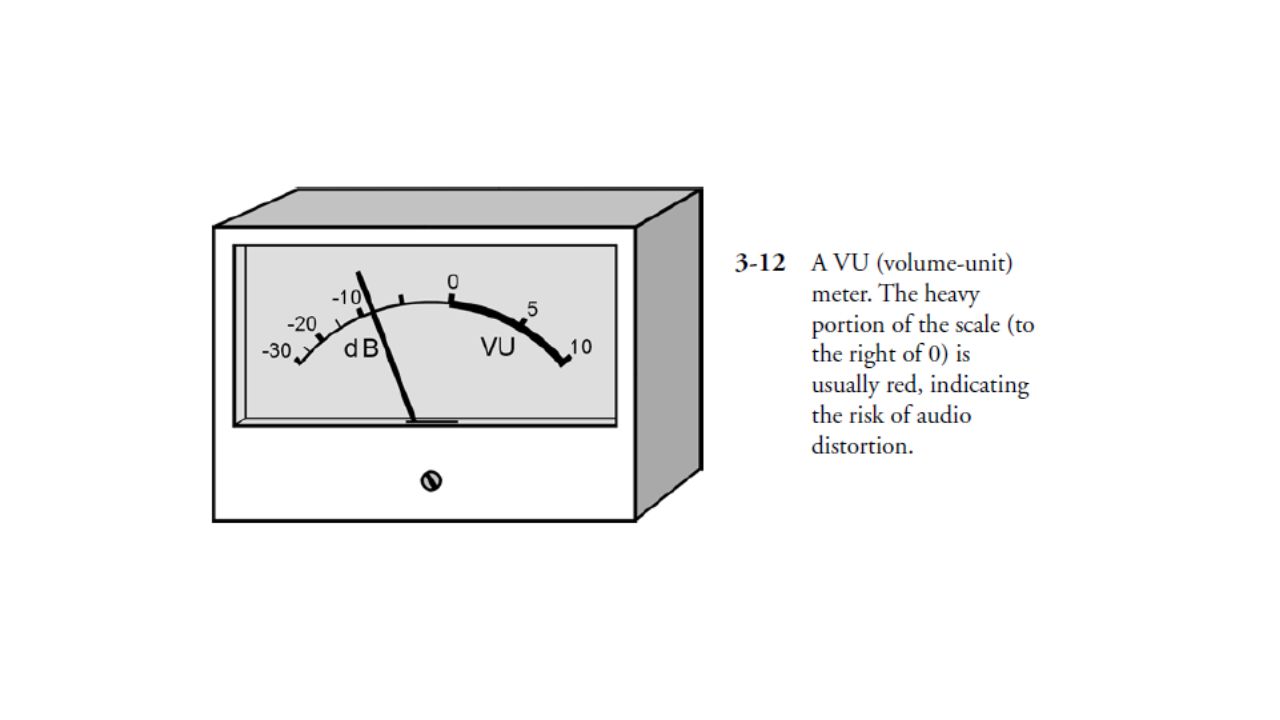
Other Meter Types Here are a few of the less common types of meters that you will occasionally encounter in electrical and electronics applications. VU and Decibel Meters In high-fidelity equipment, especially the more sophisticated amplifiers (“amps”), loudness meters are sometimes used. These are calibrated in decibels, a unit that you will often have to use, and interpret, in reference to electronic signal levels. A decibel is an increase or decrease in sound or signal level that you can just barely detect, if you are expecting the change. Audio loudness is given in volume units (VU), and the meter that indicates it is called a VU meter. The typical VU meter has a zero marker with a red line to the right and a black line to the left, and is calibrated in decibels (dB) below the zero marker and volume units above it (Fig. 3-12). The meter might also be c through the system, or as a voice comes over it, the VU meter needle kicks up. The amplifier volume should be kept down so that the meter doesn’t go past the zero mark and into the red range. If the meter does kick up into the red scale, it means that distortion is taking place within the amplifier circuit. Sound level in general can be measured by means of a sound-level meter, calibrated in decibels (dB) and connected to the output of a precision amplifier with a microphone of known sensitivity (Fig. 3-13). Have you read that a vacuum cleaner will produce “80 dB” of sound, and a large truck going by will subject your ears to “90 dB”? These figures are determined by a sound-level meter, and are defined with respect to the threshold of hearing, which is the faintest sound that a person with good ears can hear.alibrated in watts rms, an expression for audio power. As music is played
, loudness meters are sometimes used. These are calibrated in decibels, a unit that you will often have to use, and interpret, in reference to electronic signal levels. A decibel is an increase or decrease in sound or signal level that you can just barely detect, if you are expecting the change. Audio loudness is given in volume units (VU), and the meter that indicates it is called a VU meter. The typical VU meter has a zero marker with a red line to the right and a black line to the left, and is calibrated in decibels (dB) below the zero marker and volume units above it (Fig. 3-12). The meter might also be c through the system, or as a voice comes over it, the VU meter needle kicks up. The amplifier volume should be kept down so that the meter doesn’t go past the zero mark and into the red range. If the meter does kick up into the red scale, it means that distortion is taking place within the amplifier circuit. Sound level in general can be measured by means of a sound-level meter, calibrated in decibels (dB) and connected to the output of a precision amplifier with a microphone of known sensitivity (Fig. 3-13). Have you read that a vacuum cleaner will produce 80 dB of sound, and a large truck going by will subject your ears to 90 dB These figures are determined by a sound-level meter, and are defined with respect to the threshold of hearing, which is the faintest sound that a person with good ears can hear.alibrated in watts rms, an expression for audio power. As music is played")
29
through the system, or as a voice comes over it, the VU meter needle kicks up. The amplifier volume
should be kept down so that the meter doesn’t go past the zero mark and into the red range. If the meter does kick up into the red scale, it means that distortion is taking place within the amplifier circuit. Sound level in general can be measured by means of a sound-level meter, calibrated in decibels (dB) and connected to the output of a precision amplifier with a microphone of known sensitivity (Fig. 3-13). Have you read that a vacuum cleaner will produce “80 dB” of sound, and a large truck going by will subject your ears to “90 dB”? These figures are determined by a sound-level meter, and are defined with respect to the threshold of hearing, which is the faintest sound that a person with good ears can hear.
 and connected to the output of a precision amplifier with a microphone of known sensitivity. (Fig. 3-13). Have you read that a vacuum cleaner will produce 80 dB of sound, and a large truck. going by will subject your ears to 90 dB These figures are determined by a sound-level meter, and. are defined with respect to the threshold of hearing, which is the faintest sound that a person with. good ears can hear.")
30
Light Meters The intensity of visible light is measured by means of a light meter or illumination meter. It is tempting to suppose that it’s easy to make this kind of meter by connecting a milliammeter to a solar (photovoltaic) cell. As things work out, this is a good way to construct an inexpensive light meter (Fig. 3-14). More sophisticated devices use dc amplifiers, similar to the type found in a FETVM, to enhance sensitivity and to allow for several different ranges of readings. One problem with this design is that solar cells are not sensitive to light at exactly the same wavelengths as human eyes. This can be overcome by placing a colored filter in front of the solar cell, so that the solar cell becomes sensitive to the same wavelengths, in the same proportions, as human eyes. Another problem is calibrating the meter. This must usually be done at the factory, in standard illumination units such as lumens or candela. With appropriate modification, meters such as the one in Fig can be used to measure infrared (IR) or ultraviolet (UV) intensity. Various specialized photovoltaic cells have peak sensitivity at nonvisible wavelengths, including IR and UV. Pen Recorders A meter movement can be equipped with a marking device to keep a graphic record of the level of some quantity with respect to time. Such a device is called a pen recorder. The paper, with a calibrated scale, is taped to a rotating drum. The drum, driven by a clock motor, turns at a slow rate, such as one revolution per hour or one revolution in 24 hours. A simplified drawing of a pen recorder is shown in Fig A device of this kind, along with a wattmeter, can be employed to get a reading of the power consumed by your household at various times during the day. In this way you can find out when you use the most power, and at what particular times you might be using too much.
 cell. As things work out, this is a good way to construct an inexpensive light meter (Fig. 3-14). More sophisticated devices use dc amplifiers, similar to the type found in a FETVM, to enhance sensitivity and to allow for several different ranges of readings. One problem with this design is that solar cells are not sensitive to light at exactly the same wavelengths as human eyes. This can be overcome by placing a colored filter in front of the solar cell, so that the solar cell becomes sensitive to the same wavelengths, in the same proportions, as human eyes. Another problem is calibrating the meter. This must usually be done at the factory, in standard illumination units such as lumens or candela. With appropriate modification, meters such as the one in Fig can be used to measure infrared (IR) or ultraviolet (UV) intensity. Various specialized photovoltaic cells have peak sensitivity at nonvisible wavelengths, including IR and UV. Pen Recorders A meter movement can be equipped with a marking device to keep a graphic record of the level of some quantity with respect to time. Such a device is called a pen recorder. The paper, with a calibrated scale, is taped to a rotating drum. The drum, driven by a clock motor, turns at a slow rate, such as one revolution per hour or one revolution in 24 hours. A simplified drawing of a pen recorder is shown in Fig A device of this kind, along with a wattmeter, can be employed to get a reading of the power consumed by your household at various times during the day. In this way you can find out when you use the most power, and at what particular times you might be using too much.")
31
Oscilloscopes Another graphic metering device is the oscilloscope. This measures and records quantities that vary rapidly, at rates of hundreds, thousands, or millions of times per second. It creates a “graph” by throwing a beam of electrons at a phosphor screen. A cathode-ray tube, similar to the kind in a television set, is employed. Some oscilloscopes have electronic conversion circuits that allow for the use of a solid-state liquid crystal display (LCD). Oscilloscopes are useful for observing and analyzing the shapes of signal waveforms, and also for measuring peak signal levels (rather than just the effective levels). An oscilloscope can also be used to approximately measure the frequency of a waveform. The horizontal scale of an oscilloscope shows time, and the vertical scale shows the instantaneous signal voltage. An oscilloscope can indirectly measure power or current, by using a known value of resistance across the input terminals. Technicians and engineers develop a sense of what a signal waveform should look like, and then they can often tell, by observing the oscilloscope display, whether or not the circuit under test is behaving the way it should. This is a subjective measurement, because it is qualitative as well as quantitative.
. Oscilloscopes are useful for observing and analyzing the shapes of signal waveforms, and also for measuring peak signal levels (rather than just the effective levels). An oscilloscope can also be used to approximately measure the frequency of a waveform. The horizontal scale of an oscilloscope shows time, and the vertical scale shows the instantaneous signal voltage. An oscilloscope can indirectly measure power or current, by using a known value of resistance across the input terminals. Technicians and engineers develop a sense of what a signal waveform should look like, and then they can often tell, by observing the oscilloscope display, whether or not the circuit under test is behaving the way it should. This is a subjective measurement, because it is qualitative as well as quantitative.")
32
Bar-Graph Meters A cheap, simple kind of meter can be made using a string of light-emitting diodes (LEDs) or an LCD along with a digital scale to indicate approximate levels of current, voltage, or power. This type of meter, like a digital meter, has no moving parts to break. To some extent, it offers the relativereading feeling you get with an analog meter. Figure 3-16 is an example of a bar- graph meter that is used to show the power output, in kilowatts, for a radio transmitter. This meter can follow along quite well with rapid fluctuations in the reading. In this example, the meter indicates about 0.8 kW, or 800 W The chief drawback of the bar-graph meter is that it isn’t very accurate. For this reason it is not generally used in laboratory testing. In addition, the LED or LCD devices sometimes flicker when the level is between two values given by the bars. This creates an illusion of circuit instability. With bright LEDs, it can also be quite distracting.
 or an LCD along with a digital scale to indicate approximate levels of current, voltage, or power. This type of meter, like a digital meter, has no moving parts to break. To some extent, it offers the relativereading feeling you get with an analog meter. Figure 3-16 is an example of a bar- graph meter that is used to show the power output, in kilowatts, for a radio transmitter. This meter can follow along quite well with rapid fluctuations in the reading. In this example, the meter indicates about 0.8 kW, or 800 W The chief drawback of the bar-graph meter is that it isn’t very accurate. For this reason it is not generally used in laboratory testing. In addition, the LED or LCD devices sometimes flicker when the level is between two values given by the bars. This creates an illusion of circuit instability. With bright LEDs, it can also be quite distracting.")
Similar presentations