Download presentation
Presentation is loading. Please wait.

1
K-Maps, Timing Sequential Circuits: Latches & Flip-Flops Lecture 4 Digital Design and Computer Architecture Harris & Harris Morgan Kaufmann / Elsevier, 2007

2
2.7 3-input K-map

3
3-input K-map

4
K-map Definitions Complement: variable with a bar over it Literal: variable or its complement Implicant: product of literals Prime implicant: implicant corresponding to the larges circle in the K-map

5
K-map Rules Each circle must span a power of 2 (i.e. 1, 2, 4) squares in each direction Each circle must be as large as possible A circle may wrap around the edges of the K- map A one in a K-map may be circled multiple times A “don't care” (X) is circled only if it helps minimize the equation
 squares in each direction Each circle must be as large as possible A circle may wrap around the edges of the K- map A one in a K-map may be circled multiple times A don t care (X) is circled only if it helps minimize the equation.")
6
4-input K-map

7
Don’t Cares

8
Contention: X Not just 1’s and 0’s Contention: X

9
Floating: Z Tri-state Buffer

10
2.8 Building Blocks Multiplexer vs. Demultiplexer Decoder vs. Encoder Priority Encoder Adder

11
Multiplexers

12
Decoders

13
2.9 Timing See chap08.ppt of last year.

14
2.9.1 Propagation & Contamination Delay Propagation Delay: t pd = max delay from input to output Contamination Delay: t cd = min delay from input to output

15
Critical (Long) and Short Path
 and Short Path")
16
2.9.2 Glitches Glitch: when a single input change causes multiple output changes Glitches don’t cause problems because of synchronous design conventions (which we’ll talk about in a bit) But it’s important to recognize a glitch when you see one in timing diagrams
 But it’s important to recognize a glitch when you see one in timing diagrams")
17
Glitches: Example

19
Ch.3 Sequential Circuits Circuits that: –give sequence to events –have memory (short-term) –use feedback from output to input
 –use feedback from output to input")
20
3.2 State Elements State: information that determines future behavior of circuit State elements store state –Cross coupled inverter pair –SR Latch –D Latch –D Flip-flop

21
Cross Coupled inverter pair

22
3.2.1 SR Latch Bistable circuit

23
3.2.2 D Latch

24
3.2.3 D Flip-Flop How many transistors required for a D-FF ?

25
3.2.4 Registers

26
3.2.5x Enabled & Resettable FF

27
Eg.3.2– D-FF vs. D Latch

28
D Flip-Flop Input Timing Constraints Setup time: t setup = time before the clock edge that data must be stable (i.e. not changing) Setup time: t hold = time after the clock edge that data must be stable Aperture time: T o = time around clock edge that data must be stable
 Setup time: t hold = time after the clock edge that data must be stable Aperture time: T o = time around clock edge that data must be stable.")
29
D Flip-Flop Output Timing Propagation Delay: t pcq = time after clock edge that Q is guaranteed to be stable (i.e. stop changing) Contamination Delay: t ccq = time after clock edge that Q might be unstable (i.e. start changing)
 Contamination Delay: t ccq = time after clock edge that Q might be unstable (i.e. start changing).")
30
3.3 Synchronous Logic Design 3.3.1 Some Problematic Circuits

31
3.3.2 Sync. Seq. circuits

32
3.4 Finite State Machines Moore & Mealy Machine

33
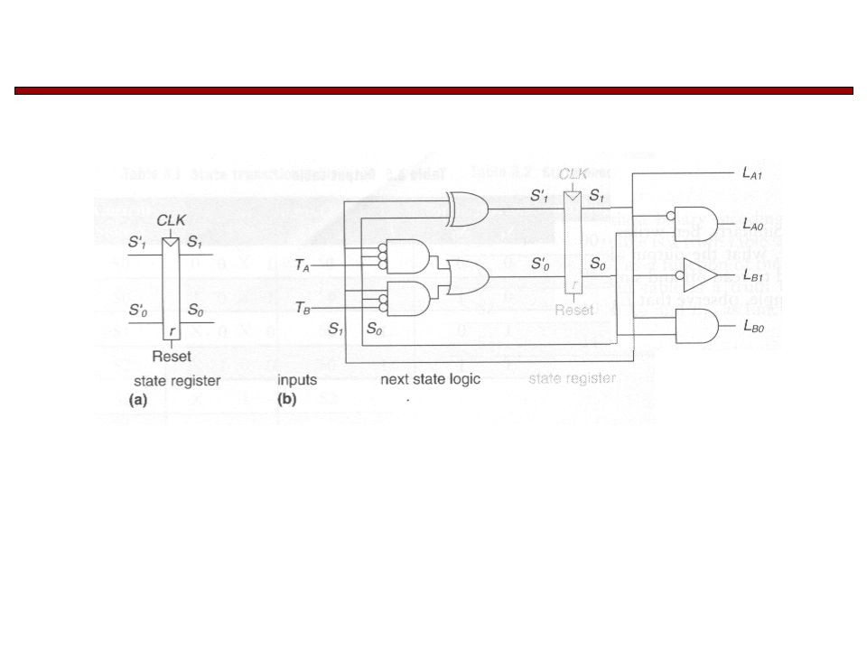
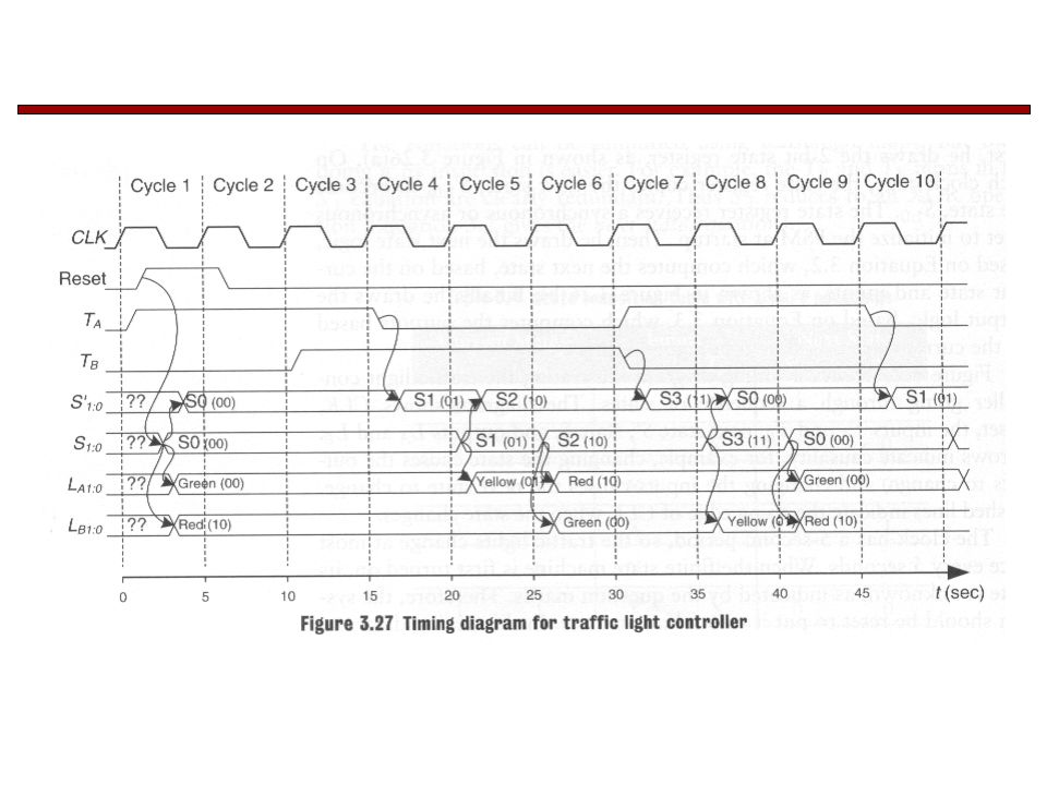
3.4 Finite State Machines

40
3.4.2 State Encoding Divide by N counter

44
Next Time Finite State Machines

Similar presentations


>")
 The slides included herein were taken from the.>")


 Lecture 22: Sequential Circuit Design (1/2) Prof. Sherief Reda Division of Engineering,>")


