Download presentation
Presentation is loading. Please wait.

1
Introduction to the Mini-Pilot Treatment System CEEN 572 Environmental Engineering Pilot Plant Laboratory

2
Mini-Pilot Treatment System Mimics both conventional and direct filtration plant Direct filtration skip sedimentation Appropriate for low-turbidity source water The min-pilot mimics CSM’s pilot system at the Golden WTP Partially automated treatment system Critical operating steps Startup Backwashing Dose adjustments Data retrieval

3
Anthracite coal (1.55) and quartz sand (2.65) More depth is utilized Dual-Media Filter
 and quartz sand (2.65) More depth is utilized Dual-Media Filter")
4
0.5 – 2 mm Anthracite

5
Dual-Media Filter

6
Headloss Through Clean Granular Filters Net available head = filter design headloss – clean- bed headloss Insignificant in slow sand and pre-coat filtration, but important in rapid filtration

7
Rapid Filtration – Filter Run Effluent turbidity characterized by three distinct segments: Ripening media conditioning (15 min - 2 hr) Sometimes contain two peaks Size and duration can be reduced by proper backwashing procedure Filter-to-waste line Effective filtration Steady state turbidity <0.1 NTU Gradual increasing in head loss Breakthrough Filter can’t hold more particles Effluent turbidity increases Headloss increases
 Sometimes contain two peaks Size and duration can be reduced by proper backwashing procedure Filter-to-waste line Effective filtration Steady state turbidity <0.1 NTU Gradual increasing in head loss Breakthrough Filter can’t hold more particles Effluent turbidity increases Headloss increases")
8
Rapid Filtration – End of Filter Run Can be triggered by several events and lead to backwash: Breakthrough Headloss Increases beyond the available head through the process Rapid filters are typically designed with 1.8-3 m (6-10 ft) available head If in specific cases neither are reached within several days: utility initiate backwash after a set period of time
 available head If in specific cases neither are reached within several days: utility initiate backwash after a set period of time")
9
Mini-Pilot Treatment System

10
Mini-Pilot Flow Diagram Feed Tank KMnO 4 Flocculation Basin turbidimeter pH Chlorine pH adjustment Overflow Coag. Backwash Lines Backwash Waste V-1 V-2 V-3 V-2 V-5 V-4 V-10 V-14 V-13 V-12 V-11 V-9V-7 V-8V-6

11
Supervisory Control And Data Acquisition (SCADA) System
 System")
12
Mini-pilot Control Panel

13
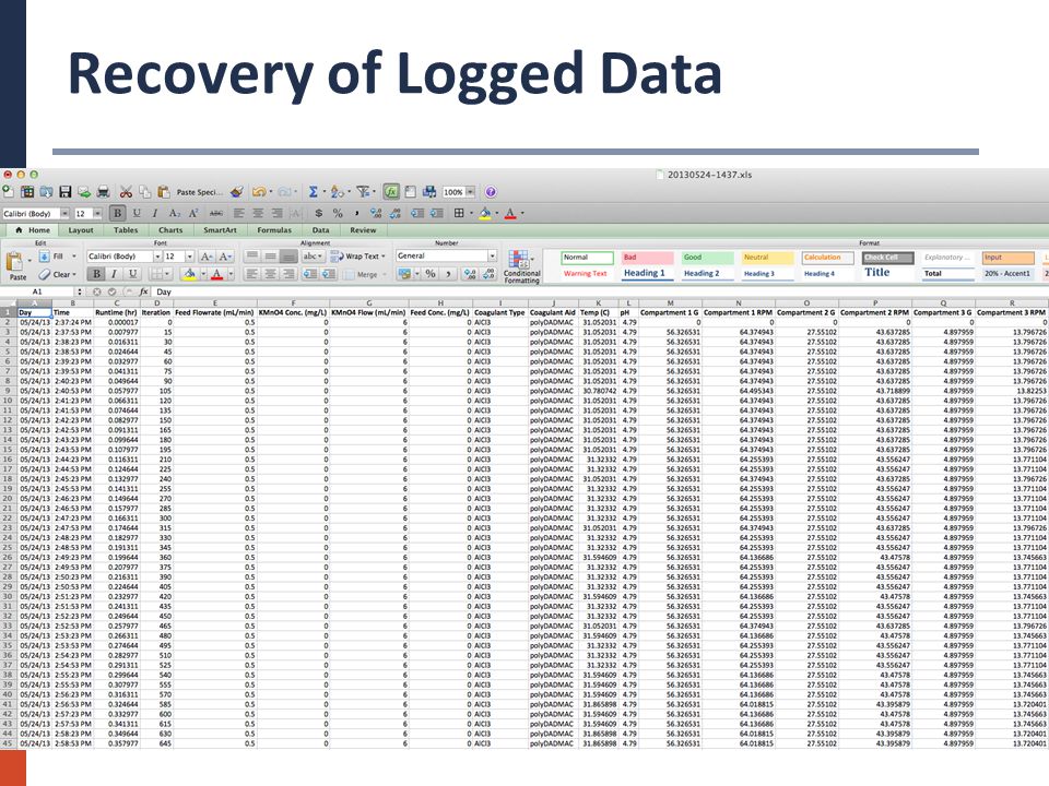
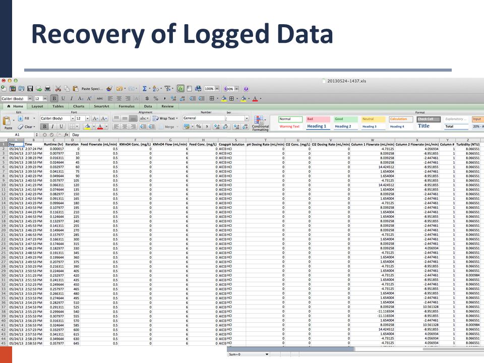
Recovery of Logged Data

16
Startup Procedure STARTUP: STEP√DESCRIPTION 1 Check the water level in the feed drums. If the water level is low, prepare to switch to the next drum. 2 Check that the chemical feed containers are full and that the tubings are fully submerged. 3 Open V-1 and close V-2, V-3, V-4, V-5, V-6, V-7, V-8, V-9, V-11, V-12, V-13, and V-14. 4 Position V-10 to send water from the desired column to the turbidimeter, and adjust V-7 and V-9 accordingly. 5 Start the submerged feed pump and check that the flow into the flocculation basin is smooth. 6 Start the SCADA system. 7 If the flocculatiion basin is empty, stop the mixers and turn them on again when the impellers are submerged. 8 Start the coagulant dosing pump and adjust the appropriate flowrate. 9 Start the KMnO4 dosing pump and adjust the appropriate flowrate. 10 Start the mixers again and adjust their G. Start with 40, 10, 5. 11 When the water level reaches the 3rd compartment overflow gate, open V-2 and V-3. 12 S l o w l y open V-4 and V-5 and adjust overflowrate to 1 - 1.5 gpm/sqft. 13 Adjust SCADA settings. 14 Adjust V-1 so that the overflow from the flocculation basins is minimal. 15 Check pH in compartment 1 and adjust by adding lime to the feed tank.

17
Operation Procedure OPERATION: STEP√DESCRIPTION 1 Frequently check the water level in the feed drum. If water level is low, prepare to switch to the next drum. 2 To switch feed drum: stop the feed pump/s; close V-1; turn off the KMnO 4 and coagulant dosing pumps; transfer the pump/s into the next drum; start the pumps; open and adjust V-1; start the KMnO 4 and coagulant dosing pumps. 3 Frequently check the turbidity level; if the level exceeds 0.3 NTU, perform column backwashing. Also, once in a while take sample from the filtrate that is routed to the turbidimeter and check turbidity on the desktop instrument 4 Frequently switch the feed to the turbidimeter (V-10) to check the filtrate turbidity of the second column. NOTE: make sure to select the measured filter column in the SCADA system because the datalogger does not distinguish between columns... 5 Frequently check the level of chemicals in the chemical containers and add stock solution if necessary 6 Obtain samples for Mn analysis at predetermined times. Samples should be taken from the feed tank and from the filtrate of each column (V-6 and V-8) 7 Occasionally check that the water level in the flocculation basins is OK and adjust V-1 to provide minimum overflow from the flocculation basin. 8 Check the pH at the flocculation basins and feed tank occasionally, and log data manually.
 to check the filtrate turbidity of the second column. NOTE: make sure to select the measured filter column in the SCADA system because the datalogger does not distinguish between columns... 5 Frequently check the level of chemicals in the chemical containers and add stock solution if necessary 6 Obtain samples for Mn analysis at predetermined times. Samples should be taken from the feed tank and from the filtrate of each column (V-6 and V-8) 7 Occasionally check that the water level in the flocculation basins is OK and adjust V-1 to provide minimum overflow from the flocculation basin. 8 Check the pH at the flocculation basins and feed tank occasionally, and log data manually..")
18
Backwashing Procedure BACKWASHING: STEP√DESCRIPTION 1 Stop the NaOH and chlorine dosing pumps, if they are operating. 2 Turn off V-2 and V-4 if you are backwashing filter column 1 or turn off V-3 and V-5 if you are backwashing filter column 2. 3 Fully open V-13 if you are backwashing filter column 1 or fully open V-14 if you are backwashing filter column 2. 4 Start the feed line for backwashing. 5 S l o w l y open V-11 (backwashing of filter 1) or V12 (backwashing of filter 2) and start backwashing. If a plug of media rises up quickly close V-11 or V-12 and slowly open it again until full fluidization is established. MAKE SURE that the expansion stops at least 2" below the head of the column. 6 Before completing the backwashing, reduce the flowrate through the filter column (V-11 or V-12) until the flow stops to establish a good mixing layer between the sand and anthracite. 7 Turn on V-2 if you backwashed filter column 1 or turn on V-3 if you backwashed filter column 2. 8Turn off V-13 if you backwashed filter column 1 or turn off V-14 if you backwashed filter column 2. 9 S l o w l y open V-4 if you backwashed filter 1 or V-5 if you backwashed filter 2 and adjust overflowrate to 1 - 1.5 gpm/sqft. 10 Start the NaOH and chlorine dosing pumps, if they are provided. 11 Check turbidity and follow Operation Procedures.
 or V12 (backwashing of filter 2) and start backwashing. If a plug of media rises up quickly close V-11 or V-12 and slowly open it again until full fluidization is established. MAKE SURE that the expansion stops at least 2 below the head of the column. 6 Before completing the backwashing, reduce the flowrate through the filter column (V-11 or V-12) until the flow stops to establish a good mixing layer between the sand and anthracite. 7 Turn on V-2 if you backwashed filter column 1 or turn on V-3 if you backwashed filter column 2. 8Turn off V-13 if you backwashed filter column 1 or turn off V-14 if you backwashed filter column 2. 9 S l o w l y open V-4 if you backwashed filter 1 or V-5 if you backwashed filter 2 and adjust overflowrate to gpm/sqft. 10 Start the NaOH and chlorine dosing pumps, if they are provided. 11 Check turbidity and follow Operation Procedures..")
19
Shutdown Procedure SHUTDOWN: STEP√DESCRIPTION 1 Perform backwashing procedure on both filter columns. 2 Stop all dosing pumps. 3 Turn off V-1. 4 Stop the feed pump/s. 5 Start emptying the flocculation basin and continue filtering until there is a 3-4" headspace in each column. 6 Turn off V-4 and V-5. 7 Stop the mixers. 8 Empty the floculation basin and pump the sludge with ShopVac. 9 Retrieve data from the datalogger and turn off the SCADA program.

20
Mini-Pilot Flow Diagram 1 2 Feed Tank KMnO 4 Flocculation Basin Coagulant turbidimeter Chlorine Backwash Lines Backwash Waste pH pH adjustment V-1 Overflow V-3 V-2 V-5 V-4 V-10 V-14 V-13 V-12 V-11 V-9V-7 V-6 V-8

Similar presentations


. Coagulation.>")


>")