Download presentation
Presentation is loading. Please wait.

1
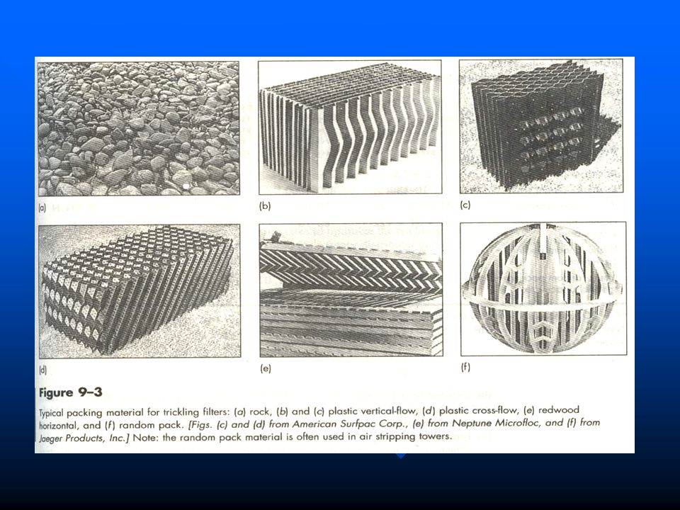
8 Attached Growth Biological Treatment Processes 8-1 Background Nonsubmerged Attached Growth Processes A trickling filter is a nonsubmerged fixed-film biological reactor using rock or plastic packing over which wastewater is distributed continously. A trickling filter is a nonsubmerged fixed-film biological reactor using rock or plastic packing over which wastewater is distributed continously.

2
The limitations of the trickling filter included a relatively high incidence of clogging, the long rest period required, headloss, and the relatively low loading that could be used. The limitations of the trickling filter included a relatively high incidence of clogging, the long rest period required, headloss, and the relatively low loading that could be used.

3
In the 1950s, plastic packing began to replace rock,which allowed the use of higher loading rates and taller filters (also known as biotowers) with less land area, improved process efficiency, and reduced clogging. In the 1950s, plastic packing began to replace rock,which allowed the use of higher loading rates and taller filters (also known as biotowers) with less land area, improved process efficiency, and reduced clogging. In the 1960s, practical designs were developed for rotating biological contactors (RBCs), where the packing is rotated in the wastewater treatment tank. In the 1960s, practical designs were developed for rotating biological contactors (RBCs), where the packing is rotated in the wastewater treatment tank. Both trickling filters and RBCs have been used as aerobic attached growth processes for BOD removal only, combined BOD removal and nitrification. Both trickling filters and RBCs have been used as aerobic attached growth processes for BOD removal only, combined BOD removal and nitrification.
 with less land area, improved process efficiency, and reduced clogging. In the 1960s, practical designs were developed for rotating biological contactors (RBCs), where the packing is rotated in the wastewater treatment tank. In the 1960s, practical designs were developed for rotating biological contactors (RBCs), where the packing is rotated in the wastewater treatment tank. Both trickling filters and RBCs have been used as aerobic attached growth processes for BOD removal only, combined BOD removal and nitrification. Both trickling filters and RBCs have been used as aerobic attached growth processes for BOD removal only, combined BOD removal and nitrification..")
4
In comparison to the activated-sludge process, disadvantages encountered for trickling filters are a poorer effluent quality in terms of BOD and TSS concentrations, greater sensitivity to lower temperatures, odor production, and uncontrolled solids sloughing events. In comparison to the activated-sludge process, disadvantages encountered for trickling filters are a poorer effluent quality in terms of BOD and TSS concentrations, greater sensitivity to lower temperatures, odor production, and uncontrolled solids sloughing events. Trickling filters and RBCs have also been used in combined processes with activated sludge to utilize the benefits of both processes, in terms of energy savings and effluent quality. Trickling filters and RBCs have also been used in combined processes with activated sludge to utilize the benefits of both processes, in terms of energy savings and effluent quality.

6
8-2 Trickling Filters The depth of the rock packing ranges from 0.9 to 2.5 m and averages 1.8 m. Rock filter beds are usually circular, and the liquid wastewater is distributed over the top of the bed by a rotary distributor. The depth of the rock packing ranges from 0.9 to 2.5 m and averages 1.8 m. Rock filter beds are usually circular, and the liquid wastewater is distributed over the top of the bed by a rotary distributor.

7
Trickling filters that use plastic packing have been built in round, square, and other shapes with depths varying from 4 to 12 m. In addition to the packing, other components of the trickling filter include a wastewater dosing or application system, an underdrain, and a structure to contain the packing. The underdrain system is important both for collecting the trickling filter effluent liquid and as a porous structure through which air can circulate. Trickling filters that use plastic packing have been built in round, square, and other shapes with depths varying from 4 to 12 m. In addition to the packing, other components of the trickling filter include a wastewater dosing or application system, an underdrain, and a structure to contain the packing. The underdrain system is important both for collecting the trickling filter effluent liquid and as a porous structure through which air can circulate.

8
In practice, a portion of the liquid collected in the underdrain system or the settled effluent is recycled to the trickling filter feed flow, usually to dilute the strength of the incoming wastewater and to maintain enough wetting to keep the biological slime layer moist. In practice, a portion of the liquid collected in the underdrain system or the settled effluent is recycled to the trickling filter feed flow, usually to dilute the strength of the incoming wastewater and to maintain enough wetting to keep the biological slime layer moist.

9
Distributor arms extend across the trickling filter inner diameter and have variable openings to provide a uniform application rate per unit area. The distributor arms are rotated by the force of the water exiting through their opening or by the use of electric drives. Distributor arms extend across the trickling filter inner diameter and have variable openings to provide a uniform application rate per unit area. The distributor arms are rotated by the force of the water exiting through their opening or by the use of electric drives. In some cases, especially for square or rectangular filters, fixed flat-spray nozzles have been used. In some cases, especially for square or rectangular filters, fixed flat-spray nozzles have been used.

10
Primary clarification is necessary before rock trickling filters. Primary clarification is necessary before rock trickling filters. In some installations, a wire-mesh screen is placed over the top of plastic packing to collect debris that can be vacuumed off periodically. In some installations, a wire-mesh screen is placed over the top of plastic packing to collect debris that can be vacuumed off periodically. The biological community in the filter includes aerobic and facultative bacteria, fungi, algae, and protozoans. Higher animals, such as worms, insect larvae, and snails, are also present. The biological community in the filter includes aerobic and facultative bacteria, fungi, algae, and protozoans. Higher animals, such as worms, insect larvae, and snails, are also present.

11
Pseudomonas, and Alcaligenes are among the bacterial species commonly associated with the trickling filter. Within the slime layer, where adverse conditions prevail with respect to growth, the filamentous forms Sphaerotilus natans and Beggiatoa will be found. In the lower reaches of the filter, the nitrifying bacteria will be present. The fungi present are also responsible for waste stabilization, but their role is usually important only under low-pH conditions. At times, fungi growth can be so rapid that the filter clogs and ventilation becomes restricted. Among the fungi species that have been identified are Fusarium, Mucor, Penicillium, Geotrichum, Sporatichum, and various yeasts. Pseudomonas, and Alcaligenes are among the bacterial species commonly associated with the trickling filter. Within the slime layer, where adverse conditions prevail with respect to growth, the filamentous forms Sphaerotilus natans and Beggiatoa will be found. In the lower reaches of the filter, the nitrifying bacteria will be present. The fungi present are also responsible for waste stabilization, but their role is usually important only under low-pH conditions. At times, fungi growth can be so rapid that the filter clogs and ventilation becomes restricted. Among the fungi species that have been identified are Fusarium, Mucor, Penicillium, Geotrichum, Sporatichum, and various yeasts.

12
Algae can grow only in the upper reaches of the filter where sunlight is available. Generally, algae do not take a direct part in waste degradation, but during the daylight hours they add oxygen to the percolating wastewater. Algae can grow only in the upper reaches of the filter where sunlight is available. Generally, algae do not take a direct part in waste degradation, but during the daylight hours they add oxygen to the percolating wastewater. The function of protozoa is to feed on the biological films and, as a result, effluent turbidity decreases and the biofilm is maintained in a higher growth state. The higher animals, such as worms, snails, and insects, feed on the biological film. The function of protozoa is to feed on the biological films and, as a result, effluent turbidity decreases and the biofilm is maintained in a higher growth state. The higher animals, such as worms, snails, and insects, feed on the biological film.

13
Bacteria in the slime layer enter an endogenous respiration state and lose their ability to cling to the packing surface. Bacteria in the slime layer enter an endogenous respiration state and lose their ability to cling to the packing surface. The liquid then washes the slime off the packing, and a new slime layer starts to grow. The phenomenon of losing the slime layer is called sloughing and is primarily a function of the organic and hydraulic loading on the filter. The hydraulic loading accounts for shear velocities, and the organic loading accounts for the rate of metabolism in the slime layer. The liquid then washes the slime off the packing, and a new slime layer starts to grow. The phenomenon of losing the slime layer is called sloughing and is primarily a function of the organic and hydraulic loading on the filter. The hydraulic loading accounts for shear velocities, and the organic loading accounts for the rate of metabolism in the slime layer.

14
Trickling Filter Classification and Applications Rock filter designs have been classified as low- or standard-rate, intermediate-rate, and high-rate. Plastic packing is used typically for high-rate designs. Much higher organic loadings have been used for rock or plastic packing designs in "roughing" applications where only partial BOD removal occurs. Rock filter designs have been classified as low- or standard-rate, intermediate-rate, and high-rate. Plastic packing is used typically for high-rate designs. Much higher organic loadings have been used for rock or plastic packing designs in "roughing" applications where only partial BOD removal occurs.

16
Low-Rate Filters Dosing tanks are small, usually with only a 2-min detention time based on twice the average design flow, so that intermittent dosing is minimized. Even so, at small plants, low nighttime flows may result in intermittent dosing and recirculation may be necessary to keep the packing moist. If the interval between dosing is longer than 1 or 2 h, the efficiency of the process deteriorates because the character of the biological slime is altered by a lack of moisture. Dosing tanks are small, usually with only a 2-min detention time based on twice the average design flow, so that intermittent dosing is minimized. Even so, at small plants, low nighttime flows may result in intermittent dosing and recirculation may be necessary to keep the packing moist. If the interval between dosing is longer than 1 or 2 h, the efficiency of the process deteriorates because the character of the biological slime is altered by a lack of moisture.

17
If the nitrifying population is sufficiently well established, and if climatic conditions and wastewater characteristics are favorable, a well-operated low rate filter can provide good BOD removal and a highly nitrified effluent. If the nitrifying population is sufficiently well established, and if climatic conditions and wastewater characteristics are favorable, a well-operated low rate filter can provide good BOD removal and a highly nitrified effluent. Odors are a common problem, especially if the wastewater is stale or septic, or if the weather is warm. Filter flies (Psychoda) may breed in the filters unless effective control measures are used. Odors are a common problem, especially if the wastewater is stale or septic, or if the weather is warm. Filter flies (Psychoda) may breed in the filters unless effective control measures are used.
 may breed in the filters unless effective control measures are used. Odors are a common problem, especially if the wastewater is stale or septic, or if the weather is warm. Filter flies (Psychoda) may breed in the filters unless effective control measures are used..")
18
Intermediate- and High-Rate Filters Recirculation of the filter effluent or final effluent permits higher organic loadings, provides higher dosing rates on the filter to improve the liquid distribution and better control of the slime layer thickness, provides more oxygen in the influent wastewater flow, and returns viable organisms. Recirculation also helps to prevent ponding in the filter and to reduce the nuisance from odors and flies. Recirculation of the filter effluent or final effluent permits higher organic loadings, provides higher dosing rates on the filter to improve the liquid distribution and better control of the slime layer thickness, provides more oxygen in the influent wastewater flow, and returns viable organisms. Recirculation also helps to prevent ponding in the filter and to reduce the nuisance from odors and flies.

19
Roughing Filters Roughing filters are high-rate-type filters that treat an organic load of more than 1.6 kg/m 3 ·d and hydraulic loadings up to 190 m 3 /m 2 ·d. Roughing filters are high-rate-type filters that treat an organic load of more than 1.6 kg/m 3 ·d and hydraulic loadings up to 190 m 3 /m 2 ·d. Two-Stage Filters Two-stage systems are also used where nitrification is required. The first-stage filter and intermediate clarifier reduce carbonaceous BOD, and nitrification takes place in the second stage. Two-stage systems are also used where nitrification is required. The first-stage filter and intermediate clarifier reduce carbonaceous BOD, and nitrification takes place in the second stage.

20
Design of Physical Facilities (1) type and physical characteristics of filter packing to be used; (2) dosing rate; (3) type and dosing characteristics of the distribution system; (4) configuration of the underdrain system; (5) provision for adequate airflow (i.e., ventilation), either natural or forced air; and (6) sealing tank design. (1) type and physical characteristics of filter packing to be used; (2) dosing rate; (3) type and dosing characteristics of the distribution system; (4) configuration of the underdrain system; (5) provision for adequate airflow (i.e., ventilation), either natural or forced air; and (6) sealing tank design.
 type and physical characteristics of filter packing to be used; (2) dosing rate; (3) type and dosing characteristics of the distribution system; (4) configuration of the underdrain system; (5) provision for adequate airflow (i.e., ventilation), either natural or forced air; and (6) sealing tank design..")
22
Distribution Systems Clearance of 150 to 225 mm should be allowed between the bottom of the distributor arm and the top of the bed. The clearance permits the wastewater streams from the nozzles to spread out and cover the bed uniformly, and it prevents ice accumulations from interfering with the distributor motion during freezing weather. Clearance of 150 to 225 mm should be allowed between the bottom of the distributor arm and the top of the bed. The clearance permits the wastewater streams from the nozzles to spread out and cover the bed uniformly, and it prevents ice accumulations from interfering with the distributor motion during freezing weather. Nozzles are spaced unevenly so that greater flow per unit of length is achieved near the periphery of the filter than at the center. Headloss through the distributor is in the range of 0.6 to 1.5 m. Nozzles are spaced unevenly so that greater flow per unit of length is achieved near the periphery of the filter than at the center. Headloss through the distributor is in the range of 0.6 to 1.5 m.

24
Underdrains The underdrain system for a rock filter usually has precast blocks of vitrified clay or fiberglass grating laid on a reinforced-concrete subfloor (see Fig. 8-5). The floor and underdrains must have sufficient strength to support the packing, slime growth, and the wastewater. The floor and underdrain block slope to a central or peripheral drainage channel at a 1 to 5 percent grade. The effluent channels are sized to produce a minimum velocity of 0.6 m/s at the average daily flowrate. Underdrains may be open at both ends, so that they may be inspected easily and flushed out if they become plugged. The underdrain system for a rock filter usually has precast blocks of vitrified clay or fiberglass grating laid on a reinforced-concrete subfloor (see Fig. 8-5). The floor and underdrains must have sufficient strength to support the packing, slime growth, and the wastewater. The floor and underdrain block slope to a central or peripheral drainage channel at a 1 to 5 percent grade. The effluent channels are sized to produce a minimum velocity of 0.6 m/s at the average daily flowrate. Underdrains may be open at both ends, so that they may be inspected easily and flushed out if they become plugged.
. The floor and underdrains must have sufficient strength to support the packing, slime growth, and the wastewater. The floor and underdrain block slope to a central or peripheral drainage channel at a 1 to 5 percent grade. The effluent channels are sized to produce a minimum velocity of 0.6 m/s at the average daily flowrate. Underdrains may be open at both ends, so that they may be inspected easily and flushed out if they become plugged. The underdrain system for a rock filter usually has precast blocks of vitrified clay or fiberglass grating laid on a reinforced-concrete subfloor (see Fig. 8-5). The floor and underdrains must have sufficient strength to support the packing, slime growth, and the wastewater. The floor and underdrain block slope to a central or peripheral drainage channel at a 1 to 5 percent grade. The effluent channels are sized to produce a minimum velocity of 0.6 m/s at the average daily flowrate. Underdrains may be open at both ends, so that they may be inspected easily and flushed out if they become plugged..")
26
Fig. 8-6 Typical under-drain system for Tower filter

27
Airflow Natural ventilation has historically been the primary means of providing airflow, but it is not always adequate and forced ventilation using low- pressure fans provides more reliable and controlled airflow. Natural ventilation has historically been the primary means of providing airflow, but it is not always adequate and forced ventilation using low- pressure fans provides more reliable and controlled airflow. In the case of natural ventilation, the driving force for airflow is the temperature difference between the ambient air and the air inside the pores. If the wastewater is colder than the ambient air, the pore air will be cold and the direction of flow will be downward. If the ambient air is colder than the wastewater, the flow will be upward. In the case of natural ventilation, the driving force for airflow is the temperature difference between the ambient air and the air inside the pores. If the wastewater is colder than the ambient air, the pore air will be cold and the direction of flow will be downward. If the ambient air is colder than the wastewater, the flow will be upward.

28
8-3 Rotating Biological Contactors An RBC consists of a series of closely spaced circular disks of polystyrene or polyvinyl chloride that are submerged in wastewater and rotated through it (see Fig. 8-7). An RBC consists of a series of closely spaced circular disks of polystyrene or polyvinyl chloride that are submerged in wastewater and rotated through it (see Fig. 8-7). The cylindrical plastic disks are attached to a horizontal shaft and are provided at standard unit sizes of approximately 3.5 m in diameter and 7.5 m in length. The cylindrical plastic disks are attached to a horizontal shaft and are provided at standard unit sizes of approximately 3.5 m in diameter and 7.5 m in length. The RBC unit is partially submerged (typically 40 percent) in a tank containing the wastewater, and the disks rotate slowly at about 1.0 to 1.6 revolutions per minute. Mechanical drives are normally used to rotate the units, but air-driven units have also been installed. The RBC unit is partially submerged (typically 40 percent) in a tank containing the wastewater, and the disks rotate slowly at about 1.0 to 1.6 revolutions per minute. Mechanical drives are normally used to rotate the units, but air-driven units have also been installed.
. An RBC consists of a series of closely spaced circular disks of polystyrene or polyvinyl chloride that are submerged in wastewater and rotated through it (see Fig. 8-7). The cylindrical plastic disks are attached to a horizontal shaft and are provided at standard unit sizes of approximately 3.5 m in diameter and 7.5 m in length. The cylindrical plastic disks are attached to a horizontal shaft and are provided at standard unit sizes of approximately 3.5 m in diameter and 7.5 m in length. The RBC unit is partially submerged (typically 40 percent) in a tank containing the wastewater, and the disks rotate slowly at about 1.0 to 1.6 revolutions per minute. Mechanical drives are normally used to rotate the units, but air-driven units have also been installed. The RBC unit is partially submerged (typically 40 percent) in a tank containing the wastewater, and the disks rotate slowly at about 1.0 to 1.6 revolutions per minute. Mechanical drives are normally used to rotate the units, but air-driven units have also been installed..")
29
A submerged RBC design was also introduced in the early 1980s but has seen limited applications. The submergence is 70 to 90 percent and air-drive units are used to provide oxygen and rotation. The advantages claimed for the submerged unit are reduced loadings on the shaft and bearings, improved biomass control by air agitation, the ability to use larger bundles of disks, and ease of retrofit into existing aeration tanks. A submerged RBC design was also introduced in the early 1980s but has seen limited applications. The submergence is 70 to 90 percent and air-drive units are used to provide oxygen and rotation. The advantages claimed for the submerged unit are reduced loadings on the shaft and bearings, improved biomass control by air agitation, the ability to use larger bundles of disks, and ease of retrofit into existing aeration tanks. To prevent algae growth, protect the plastic disks from the effects of ultraviolet exposure, and to prevent excessive heat loss in cold weather, RBC units are covered (see Fig. 8-7b). To prevent algae growth, protect the plastic disks from the effects of ultraviolet exposure, and to prevent excessive heat loss in cold weather, RBC units are covered (see Fig. 8-7b).
. To prevent algae growth, protect the plastic disks from the effects of ultraviolet exposure, and to prevent excessive heat loss in cold weather, RBC units are covered (see Fig. 8-7b)..")
Similar presentations


>")


