Download presentation
Presentation is loading. Please wait.

1
Trickling Filters and Rotary Biological Contactors
CE - 370

2
Trickling Filters Trickling filters are composed of:
Influent pipe Rotary distribution Filter bed Underdrain system Effluent pipe At downstream, a sedimentation tank is used to remove microbial growth that sloughs from the medium Medium Crushed stone Large gravel Slag Plastic redwood

3
Figs

4
Classifications of Trickling Filters
Trickling filters are classified into: Low-rate or standard-rate Intermediate-rate High-rate Super-rate Classification is according to: Organic loading Unit liquid loading Recycle employed

5
Low-rate or Standard-rate Filters
Organic loading = 0.08 to 0.32 kg BOD5/m3-day Unit liquid loading = 1 to 4 m3/m2-day Bed depth = 1.5 to 3 m Recycle is employed at times when flow is not enough to turn the rotary distributor (night time) Usually single-stage BOD5 removal = 90 to 95 % Effluent BOD5 = 12 to 25 mg/l Can achieve better nitrification than high-rate filters Media volume is much greater than high-rate filters
 Usually single-stage. BOD5 removal = 90 to 95 % Effluent BOD5 = 12 to 25 mg/l. Can achieve better nitrification than high-rate filters. Media volume is much greater than high-rate filters.")
6
Intermediate-rate Filters
Organic loading = 0.24 to 0.48 kg BOD5/m3-day Unit liquid loading = 4 to 10 m3/m2-day Bed depth = Recycle may or may not be employed on continuous basis, it is employed at times when flow is not enough to turn the rotary distributor (night time) May be single-stage or two-stage BOD5 removal = 85 to 90 % Effluent BOD5 = 20 to 30 mg/l
 May be single-stage or two-stage. BOD5 removal = 85 to 90 % Effluent BOD5 = 20 to 30 mg/l.")
7
High-rate Filters Organic loading = 0.32 to 1.0 kg BOD5/m3-day
Unit liquid loading = 10 to 40 m3/m2-day Bed depth = 1 to 2 m Recycle is employed continuously May be single-stage or two-stage BOD5 removal Single-stage = 75 to 80 % Two-stage = 85 to 90 % Effluent BOD5 Single-stage = 40 to 50 mg/l Two-stage = 20 to 30 mg/l Can not achieve a highly nitrified effluent

8
Super-rate Filters Organic loading = 0.80 to 6.0 kg BOD5/m3-day
Unit liquid loading = 40 to 200 m3/m2-day Bed depth = 4.5 to 12 m Recycle is continuous Medium is always synthetic plastic (most common) or redwood Plastic media has a specific surface area (surface area per unit volume) that is from 2 to 5 time that for stone media Microbial growth is proportional to surface area Can achieve a nitrified effluent at low loadings
 or redwood. Plastic media has a specific surface area (surface area per unit volume) that is from 2 to 5 time that for stone media. Microbial growth is proportional to surface area. Can achieve a nitrified effluent at low loadings.")
11
Trickling Filters Energy cost per mass of BOD5 removed is less than that of activated sludge Super-rate filters can be used ahead of activated sludge (for high-strength wastewater) Single-stage and two-stage trickling filters are upgraded by adding activated sludge process or a shallow polishing pond downstream
 Single-stage and two-stage trickling filters are upgraded by adding activated sludge process or a shallow polishing pond downstream.")
12
Mechanisms in Biological Filtration
When wastewater passes over a microbial growth, organic matter and O2 are sorbed by the growth Aerobic bio-oxidation occurs End-products are released As time passes, the microbial film becomes thicker due to growth of new cells The film slough off the medium

14
Mechanisms in Biological Filtration
Most of the biological growth is aerobic Growth immediate to the medium surface is usually anaerobic The amount of organic removed per meter of bed depth is greatest at top of the filter and smallest at bottom Nitrifying growth is taking place at the lower depths of the filter Recycling the effluent increases the removal efficiency Microbial growth sloughed will be removed in final clarifier The sludge is sent to the head of the plant and removed in the primary sedimentation tank

16
Filter Performance Kinetic Equations
The rate of organic removal per interval of depth is proportional to the remaining concentration of removable organic matter: - dL/dD = kL dL is an increment of remaining organic concentration dD is an increment of depth L is the remaining removable organic concentration (BOD) Since dD is proportional to an increment of time dt, then (LD / L) = 10-kD LD = removable ultimate first-stage BOD concentration at depth D L = removable ultimate fist-stage BOD concentration applied to the bed k = rate constant D = depth of bed, ft (m)
 Since dD is proportional to an increment of time dt, then. (LD / L) = 10-kD. LD = removable ultimate first-stage BOD concentration at depth D. L = removable ultimate fist-stage BOD concentration applied to the bed. k = rate constant. D = depth of bed, ft (m)")
17
Kinetic Equations For low-rate filters and flow of 1.88 to 5.61 m3/m2-day k = 0.574 Removable fraction = 90% For high-rate filters operated at flow 18.8 m3/m2-day k = 0.494 Removable fraction = 78.4% The following equation was developed k2 = k (T2- 20) k2 is rate at T2 ; k20 is the rate at 20 C
 k2 is rate at T2 ; k20 is the rate at 20 C.")
18
Kinetic Equations Another performance equation was developed based on the specific rate of substrate removal (-1/X)(dS/dt) = kS (1/X)(dS/dt) = specific rate of substrate utilization, mass/(mass microbes)(time) (dS/dt) = rate of substrate utilization, mass/(volume)(time) k = rate constant, volume/(mass microbes)(time) S = substrate concentration, mass/volume
(dS/dt) = kS. (1/X)(dS/dt) = specific rate of substrate utilization, mass/(mass microbes)(time) (dS/dt) = rate of substrate utilization, mass/(volume)(time) k = rate constant, volume/(mass microbes)(time) S = substrate concentration, mass/volume.")
19
Kinetic Equations Re-arrange and integrate (St/S0) = e-kXt
k = rate constant X = average cell mass concentration, mass/volume St = substrate concentration after the contact time t, mass/volume S0 = substrate concentration applied to the filter, mass/volume X is proportional to the specific surface area of the packing, As (m2 of the surface per bulk m3 of the volume) X ~ As
 X ~ As.")
20
Kinetic Equations The mean contact time, t, for a filter is given by:
t = mean contact time D = depth of filter QL = unit liquid loading or surface loading C, n = experimental constants

21
Kinetic Equations From the above equations
St = substrate concentration in the filter effluent, mass/volume S0 = substrate concentration applied to the filter, mass/volume K = rate constant As = specific surface area of the packing, area/volume D = filter depth QL = unit liquid loading or surface loading m, n = experimental constants

22
Kinetic Equations Value of n
Depends of the flow characteristics through the packing Usually between 0.5 to 0.67 The equation can be further simplified by combing KAsm K is the new rate constant K is between 0.01 and 0.1 K can be obtained from pilot-scale plant

23
Kinetic Equations To correct K for temperature
KT = rate constant at temperature T, C K20 = rte constant at 20 C T = temperature, C

24
Kinetic Equations A more common kinetic equation for filter with stone media is: St = BOD5 in the filter effluent, mg/l S0 = BOD5 in the wastewater discharged on the filter bed, mg/l C = 2.5 for USCS units and for SI units D = filter depth, ft (m) QL = unit liquid loading, MG/acre-day (m3/m2-day)
 QL = unit liquid loading, MG/acre-day (m3/m2-day)")
25
Examples 17.1 and 17.2

26
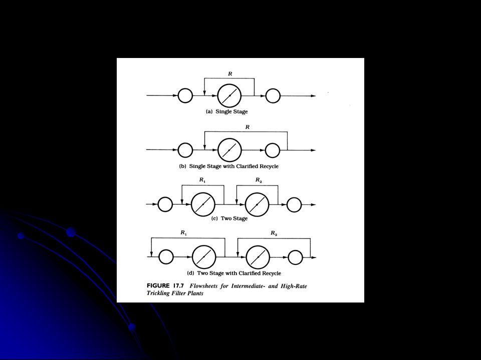
Flowsheets for Intermediate- and High-Rate Trickling Filter Plants

29
Filter Details

31
Operational Problems Less problems than activated sludge processes
Floating sludge may be encountered if anaerobic conditions occur within the settled sludge Presence of fly that breed in the filter Can be controlled by allowing the medium to stay submerged Odor when low-rate filters are employed and wastewater is stale when it reaches the plant

35
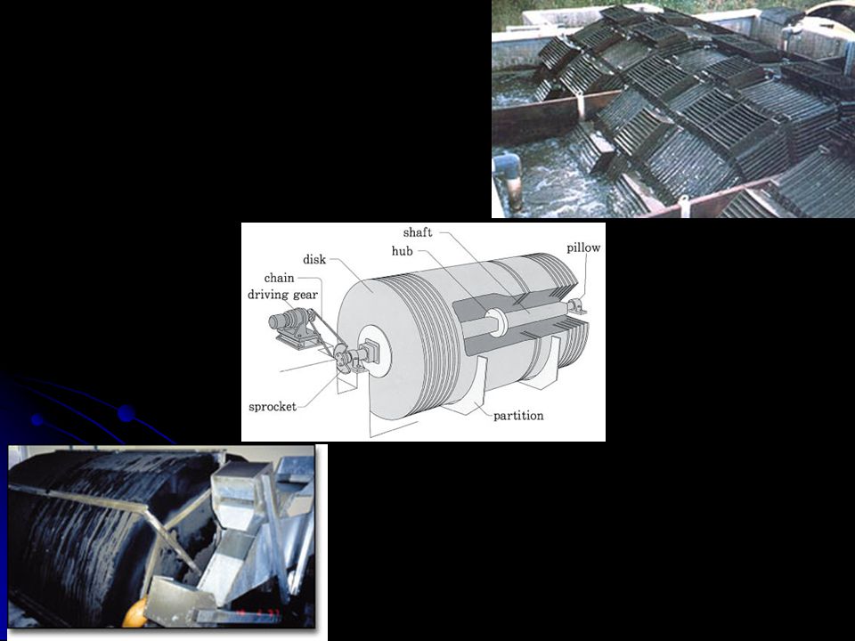
Rotary Biological Contactors

40
Main Characteristics Composed of multiple discs mounted on a horizontal shaft that passes through the center of the discs Wastewater flow is perpendicular to the shaft About 40% of the total disc area is submerged Biological film grows on the disc As the shaft rotates, the biological growth (film) sorbs organic matter from wastewater Oxygen is adsorbed from air to keep aerobic condition Multiple stages of RBC is used to achieve greater BOD5 removal Sloughed biological growths are removed in final clarifiers No recycle is employed Biological activities are reduced during cold weather In cold climates, RBCs are covered to avoid heat loss and protect against freezing
 sorbs organic matter from wastewater. Oxygen is adsorbed from air to keep aerobic condition. Multiple stages of RBC is used to achieve greater BOD5 removal. Sloughed biological growths are removed in final clarifiers. No recycle is employed. Biological activities are reduced during cold weather. In cold climates, RBCs are covered to avoid heat loss and protect against freezing.")
41
Design The main design parameter is the wastewater flowrate per surface area of the discs Is called the hydraulic loading (m3/day-m2) Indirectly represents the F/M ratio Wastewater flowrate is related to mass of substrate Disc surface area is related to mass of microbes For municipal wastewater, four (4) stages are used, but if nitrification is required, five (5) stages are employed Advantages Low energy requirement compared to activated sludge Ability to handle shock loadings Ability of multistage to achieve high degree of nitrification
 stages are used, but if nitrification is required, five (5) stages are employed. Advantages. Low energy requirement compared to activated sludge. Ability to handle shock loadings. Ability of multistage to achieve high degree of nitrification.")
42
Kinetics Kinetic equation of RBC is based on substrate removal
(1/X)(dS/dt) = specific rate of substrate utilization (dS/dt) = rate of substrate utilization k = rate constant S = substrate concentration Q = flowrate S0 = influent substrate concentration Se = effluent substrate concentration X = cell mass A = disc area
(dS/dt) = specific rate of substrate utilization. (dS/dt) = rate of substrate utilization. k = rate constant. S = substrate concentration. Q = flowrate. S0 = influent substrate concentration. Se = effluent substrate concentration. X = cell mass. A = disc area.")
43
Kinetics This equation is in the form of ( y = mx )
")
45
Kinetics

46
Example 17.5

Similar presentations


>")


. Advantages:Simplicity simple to construct simple to construct simple to operate and maintain simple to operate and.>")
