Download presentation
Presentation is loading. Please wait.

2
Chapter 10 Input / Output Organization CS 147 Yueyang Zhou

3
Overview Some examples of I/O Devices Synchronous data transfers Asynchronous data transfers Source-initiated data transfer without handshaking Destination-initiated data transfer without handshaking Source-initiated data transfer with handshaking Destination-initiated data transfer with handshaking Programmed I/O A thermostat The control algorithm of Thermostat

4
Examples of I/O Devices A personal computer Keyboard (input) Mouse(input) Monitor(output) Printer(output) Microwave ovens Sensor(input) Output signals
 Mouse(input) Monitor(output) Printer(output) Microwave ovens Sensor(input) Output signals")
5
Devices Interface Controler Data I/O CPU Address bus Data bus Control bus

6
Synchronous data transfers Synchronous transfers usually occur when peripherals are located within the same computer as the CPU because their close proximity allows them to share a common clock and because data does not have to travel very far physically, which becomes a concern at a higher clock frequencies.

7
Asynchronous data transfers A computer can make use of asynchronous data transfers when synchronous transfers are not viable. Asynchronous transfers use control signals and their associated hardware to coordinate the movement of data. These data transfer do not require that the source and destination use the same system clock. There are four types of asynchronous data transfers.

8
The source outputs its data. Then strobes a control signal for a set amount of time. The destination device reads in the data during this time. The source device next desserts the strobe and stops outputting data.

10
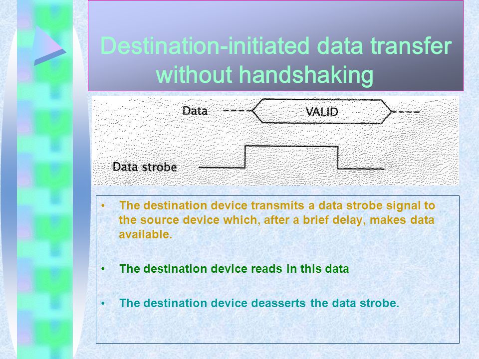
Destination-initiated data transfer without handshaking The destination device transmits a data strobe signal to the source device which, after a brief delay, makes data available. The destination device reads in this data The destination device deasserts the data strobe.

12
For some devices, particularly electromechanical devices, do not require the same amount of time for every transfer, they can use handshaking to coordinate their transfers. Handshaking uses an additional control signal to indicate that data is ready or has been read in.

13
The timing for a source- initiated data transfer with handshaking

14
The source sets the data request signal high. Makes valid data available to the destination device The destination device reads in data. The destination device sends a data acknowledge signal to the source. The source sets its data request line low and stops sending data. The destination then resets its data acknowledge signal.

16
Similar to that of the source-initiated data transfer using handshaking, except that the data-acknowledge signal is replaced by a data-ready signal.

18
Definition: Programmed I/O is exactly what its name implies: A program instruction causes the CPU to input or output data. Programmed I/O can be either isolated or memory mapped. Isolated I/O uses separate instructions to access I/O ports. Memory-mapped I/O treats I/O ports as memory locations.

19
It perform the following sequence of operation: 1.Read temperature from external sensor. 2.If (temperature > thermostat setting +2) then turn on air conditioner. 3.If (temperature < thermostat setting and air conditioner is on) then turn off air conditioner. 4.If (temperature < thermostat setting – 2) then turn on heat. 5.If (temperature > thermostat setting and heat is on) then turn off heat. 6.Go to start of sequence.
 then turn on air conditioner. 3.If (temperature < thermostat setting and air conditioner is on) then turn off air conditioner. 4.If (temperature < thermostat setting – 2) then turn on heat. 5.If (temperature > thermostat setting and heat is on) then turn off heat. 6.Go to start of sequence..")
20
1.Illustration An input port at address FFFFH Whenever the illustration LDAC FFFF is executed, the CPU reads data from this port and stores it in its accumulator register. 2.Implementation Design the hardware for the input port Makes data available to the CPU The CPU would read the data from the data bus

22
1.The tri-state buffers are only enable when: The address bus contains the value FFFFH Control bus signal READ= 1 2.Data from the input port passes on to the data bus of the computer. 3.Data is read in by the CPU. 4.Data stored in data register. 5.CPU moves data from its data register into its accumulator.

23
1.The software programmer is responsible for: The CPU never attempts to access memory location FFFFH The input port has been assigned to this address It cannot be used by a memory location 2.This is one of the limitation of memory-mapped I/O.

24
1.The CPU reads in the current temperature from the memory-mapped input port at address FFFH 2.The thermostat setting from the port at address FFFE 3.The CPU controls the heating and air conditioning system. 4.Writing one of the four values to the output port at address FFFD 01 = turn on air conditioning 02 = turn off air conditioning 03 = turn on heat 04 = turn off heat 5.The current status is stord in memory location 1000H 00 = heat and air conditioning are both off FF = heat is on FE = air conditioning is on

26
NEW INSTRUCTION InstructionInstruction Code Operation INPT0010 0000 TAC Input port T OTPT0010 0001 TOutput port T AC

27
New control signals 1.When using isolated I/O Need a signal to distinguish between memory references and I/O references 2.Without this signal, it is not possible to tell whether an address refers to a memory location or to an I/O port 3.We create a new signal called IO IO = 1 for input/ output operations IO = 0 for memory reference operations

28
1.Difference between INPT instruction and the LDAC instruction. In state LDAC4, the LDAC instruction reads data from memory. During the corresponding state of the INPT instruction’s execute routine, it must read data from an input port.

29
The modification the state diagram for the CPU

30
Modify the CPU hardware for the new instruction

31
Summary Synchronous data transfers Asynchronous data transfers Source-initiated data transfer without handshaking Destination-initiated data transfer without handshaking Source-initiated data transfer with handshaking Destination-initiated data transfer with handshaking Programmed I/O A thermostat

Similar presentations


 –Address bus –Data bus –Control bus.>")

 Lecturer: Hui.>")


Explain the limitations of flash memory. 2)Define wear leveling. 3)Define the term IO Transaction 4)Define the terms synchronous.>")


>")
. I/O Devices Input/output (I/O) devices provide the means to interact with the “outside world”. An I/O device.>")