Download presentation
Presentation is loading. Please wait.

1
Functions and Functional Blocks
COE 202 Digital Logic Design Dr. Aiman El-Maleh College of Computer Sciences and Engineering King Fahd University of Petroleum and Minerals

2
Outline Enabling function Decoders
Implementing Functions using Decoders Encoders Multiplexers Implementing Functions using Multiplexers DeMultiplexers Design Examples using MSI Functional Blocks

3
Functions and Functional Blocks
Will consider functions that are useful in designing other combinational and sequential circuits Such circuits can be implemented using a set of functional blocks In the past, many functional blocks were implemented as separate SSI (small scale integration), MSI, and LSI integrated circuits (ICs) Today, they are often used as parts in a design library for use within larger VLSI circuits 10s s s millions gates/chip SS MS LS VLS (Small Scale) (Medium Scale) (Large Scale) (Very Large Scale)
, MSI, and LSI integrated circuits (ICs) Today, they are often used as parts in a design library for use within larger VLSI circuits. 10s 100s 1000s millions gates/chip. SS MS LS VLS. (Small Scale) (Medium Scale) (Large Scale) (Very Large Scale)")
4
Enabling Function Enable: Allow an input signal to pass through to an output Disable: block an input signal from passing through to an output, replacing it with a fixed state (1, 0, or HiZ) Disable: EN = 0 in both cases When disabled, output = 0 When disabled, output = 1
 Disable: EN = 0 in both cases. When disabled, output = 0. When disabled, output = 1.")
5
Decoders A decoder is a circuit that decodes an input code. Given a binary code of n-bits, a decoder will tell which code is this out of the 2n possible codes. A decoder may have enable line In general, output i equals 1 if and only if the input binary code has a value of i. Thus, each output line equals 1 at only one input combination but is equal to 0 at all other combinations. Thus, the decoder generates all of the 2n minterms of n input variables.

6
2-to-4 Decoder A 2-to-4 decoder contains two inputs denoted by A1 and A0 and four outputs denoted by D0, D1, D2, and D3. For each input combination, one output line is activated, that is, the output line corresponding to the input combination becomes 1, while other lines remain inactive. For example, an input of 00 at the input will activate line D0. 01 at the input will activate line D1, and so on.

7
2-to-4 Decoder Notice that, each output of the decoder is actually a minterm resulting from a certain combination of the inputs, that is: ( minterm m0) ( minterm m1) ( minterm m2) ( minterm m3)
 ( minterm m1) ( minterm m2) ( minterm m3)")
8
2-to-4 Decoder with Enable
Attach m output-enabling gates opened by the EN input Note use of X’s to denote both 0 and 1 at the inputs Combination containing two X’s represent four input binary combinations

9
3-to-8 Decoder In a three to eight decoder, there are three inputs and eight outputs, A0 is the least significant variable, while A2 is the most significant variable. Each output represents one minterm For example, for input combination A2A1A0 = 001, output line D1 equals 1 while all other output lines equal 0’s It should be noted that at any given instance of time, one and only one output line can be activated.

10
3-to-8 Decoder Implementation
Notice that each output line is the minterm corresponding to the input code, i.e. D5 is m5

11
Hierarchical 2-to-4 Decoder Design

12
Hierarchical 3-to-8 Decoder Design

13
Decoder Expansion Example: 3-to-8 from two 2-to-4 with EN
Using two 2-to-4 decoders & one 1-to-2 decoder

14
Implementing Functions using Decoders
Implementing functions of n inputs and m requires: Specification: As a Truth Table (has n input columns and m output columns) or m sum of minterms (SOm) expressions Implementation requires: One n-to-2n-line decoder m OR gates, one for each output Procedure: From the truth table: For each ‘1’ in the truth table of an output, connect the corresponding Di of the decoder to the OR of that output From the m minterm expressions: Connect the decoder Di’s corresponding to the minterms of each output to the OR of that output
 or m sum of minterms (SOm) expressions. Implementation requires: One n-to-2n-line decoder. m OR gates, one for each output. Procedure: From the truth table: For each ‘1’ in the truth table of an output, connect the corresponding Di of the decoder to the OR of that output. From the m minterm expressions: Connect the decoder Di’s corresponding to the minterms of each output to the OR of that output.")
15
Implementing Functions using Decoders
Example:1-bit adder (Full Adder) We need: 2 SOm expressions 3-to-23 Decoder 2 OR gates of appropriate # of inputs Larger # of 1’s require larger ORs. If so, Consider expressing F and using a NOR instead! LSB
 We need: 2 SOm expressions. 3-to-23 Decoder. 2 OR gates of appropriate # of inputs. Larger # of 1’s require larger ORs. If so, Consider expressing F and using a NOR instead! LSB.")
16
Encoders An encoder performs the inverse operation of a decoder.
It has 2n inputs, and n output lines. Only one input can be logic 1 at any given time (active input). All other inputs must be 0’s. Output lines generate the binary code corresponding to the active input.
. All other inputs must be 0’s. Output lines generate the binary code corresponding to the active input.")
17
Octal-to-Binary Encoder
Assuming only 1 (and at least 1) Input line being active at a time Only 8 rows are relevant, out of the 2^8 = 256 rows
 Input line being. active at a time. Only 8 rows are. relevant, out of the 2^8 = 256 rows.")
18
Octal-to-Binary Encoder
Note that not all input combinations are valid. Valid combinations are those which have exactly one input equal to logic 1 while all other inputs are logic 0’s. Since, the number of inputs = 8, K-maps cannot be used to derive the output Boolean expressions. The encoder implementation, however, can be directly derived from the truth table: Since A0 = 1 if the input octal digit is 1 or 3 or 5 or 7, then we can write: A0 = E1 + E3 + E5+ E7 Likewise, A1 = E2 + E3 + E6+ E7, and similarly A2 = E4 + E5 + E6+ E7 Thus, the encoder can be implemented using three 4- input OR gates.

19
Major Limitation of Encoders
Exactly one input must be active at any given time. If the number of active inputs is less than one or more than one, the output will be incorrect. For example, if E3 = E6 = 1, the output of the encoder A2A1A0 = 111, which implies incorrect output. Two Problems to Resolve: 1. If two or more inputs are active at the same time, what should the output be? 2. An output of all 0's is generated in 2 cases: when all inputs are 0 when E0 is equal to 1. How can this ambiguity be resolved?

20
Major Limitation of Encoders
Solution To Problem 1: Use a Priority Encoder which produces the output corresponding to the input with higher priority. Inputs are assigned priorities according to their subscript value; e.g. higher subscript inputs are assigned higher priority. In the previous example, if E3 = E6 = 1, the output corresponding to E6 will be produced (A2A1A0 = 110) since E6 has higher priority than E3. Solution To Problem 2: Provide one more output signal V to indicate validity of input data. V = 0 if none of the inputs equals 1, otherwise it is 1
 since E6 has higher priority than E3. Solution To Problem 2: Provide one more output signal V to indicate validity of input data. V = 0 if none of the inputs equals 1, otherwise it is 1.")
21
4-to-2 Priority Encoders
Sixteen input combinations. Three output variables A1, A0, and V. V is needed to take care of situation when all inputs are equal to zero.

22
4-to-2 Priority Encoders

23
Multiplexers: 2n-to-1 A typical multiplexer has:
A multiplexer (MUX) selects information from one of 2n input line and directs it toward a single output line. A typical multiplexer has: 2n information inputs (I(2n – 1), … I0) (to select from) 1 Output Y (to select to) n select control (address) inputs (Sn - 1, … S0) (to select with) Implemented using decoders MUX selection circuits can be duplicated m times (with the same selection controls in parallel) to provide m-wide data widths
 selects information from one of 2n input line and directs it toward a single output line. A typical multiplexer has: 2n information inputs (I(2n – 1), … I0) (to select from) 1 Output Y (to select to) n select control (address) inputs (Sn - 1, … S0) (to select with) Implemented using decoders. MUX selection circuits can be duplicated m times (with the same selection controls in parallel) to provide m-wide data widths.")
24
2-to-1 MUX The single selection variable S has two values:
S = 0 selects input I0 S = 1 selects input I1 3-input K-map optimization gives the output equation: The circuit: Can be seen As: 1-to-2 decoder + Enabling + Selection Truth Table 2n Minterms 2n I Inputs

25
4-to-1 MUX Using 2-to-4 decoder +4 2-input AND + 4-input OR for Enabling/Selection # of the ANDs 2-to-4 Size of the Select Inputs = Log2 (4) X
 X.")
26
4-to-1 MUX A 4-to-1 MUX can be implemented using three 2-to-1 MUXs.
F = s1’s0’ I0 + s1’s0 I1 + s1s0’ I2 + s1s0 I3 = s1’ (s0’ I0 + s0 I1)+ s1 (s0’ I2 + s0 I3) I0 2x1 MUX I1 2x1 MUX S0 F I2 2x1 MUX S1 I3 S0
+ s1 (s0’ I2 + s0 I3) I0. 2x1. MUX. I1. 2x1. MUX. S0. F. I2. 2x1. MUX. S1. I3. S0.")
27
Quad 2-to-1 MUX Given two 4-bit numbers A and B, design a multiplexer that selects one of these 2 numbers based on some select signal S. Obviously, the output (Y) is a 4-bit number. The 4-bit output number Y is defined as follows: Y = A IF S=0, otherwise Y = B The circuit is implemented using four 2x1 Muxes, where the output of each of the Muxes gives one of the outputs (Yi).
 is a 4-bit number. The 4-bit output number Y is defined as follows: Y = A IF S=0, otherwise Y = B. The circuit is implemented using four 2x1 Muxes, where the output of each of the Muxes gives one of the outputs (Yi).")
28
Quad 2-to-1 MUX A0 2x1 MUX Y0 B0 S A1 2x1 MUX Y1 B1 S A2 2x1 MUX Y2 B2

29
16-to-1 MUX

30
Implementing Functions using Multiplexers

31
Implementing Functions using Multiplexers
Implementing a function of n inputs and m outputs (n to m) requires: Truth table, or m Sum-of-minterms expressions m-wide 2n-to-1 multiplexer Design: In the order they appear in the truth table: Apply the function inputs to the multiplexer select inputs Sn -1, … , S0 Label the outputs of the multiplexer with the output variables Value-fix the information inputs to the multiplexer using the values from the truth table. For don’t cares, use either 0 or 1.
 requires: Truth table, or m Sum-of-minterms expressions. m-wide 2n-to-1 multiplexer. Design: In the order they appear in the truth table: Apply the function inputs to the multiplexer select inputs Sn -1, … , S0. Label the outputs of the multiplexer with the output variables. Value-fix the information inputs to the multiplexer using the values from the truth table. For don’t cares, use either 0 or 1.")
32
Implementing Functions using Multiplexers
Example: 1-bit adder

33
Implementing Functions using Multiplexers
Example: 1-bit adder, a more efficient approach

34
Implementing Functions using Multiplexers
Example: F (A,B,C,D) = m(1,3,4,11,12,13,14,15) 16 rows in truth table 16-to-1 MUX (conventional approach) But using the efficient approach … will use only an 8-to-1 MUX + 1 inverter
 = m(1,3,4,11,12,13,14,15) 16 rows in truth table. 16-to-1 MUX. (conventional. approach) But using the efficient. approach … will use. only an 8-to-1 MUX. + 1 inverter.")
35
Implementing Functions using Multiplexers
Example: F (A,B,C) = m(1,2,6,7)
 = m(1,2,6,7)")
36
Shannon's Expansion The cofactor of f(x1,x2,…,xi,…,xn) with respect to variable xi is fxi = f(x1,x2,…,xi=1,…,xn) The cofactor of f(x1,x2,…,xi,…,xn) with respect to variable xi’ is fxi’ = f(x1,x2,…,xi=0,…,xn) Theorem: Shannon's Expansion Any function can be expressed as sum of products (product of sums) of n literals, minterms (maxterms), by recursive expansion.
 with respect to variable xi’ is fxi’ = f(x1,x2,…,xi=0,…,xn) Theorem: Shannon s Expansion. Any function can be expressed as sum of products (product of sums) of n literals, minterms (maxterms), by recursive expansion.")
37
Shannon's Expansion Example: f = ab + ac + bc
fa = b + c fa’ = bc F = a fa + a’ fa’ = a (b + c) + a’ (bc) Using Shanon’s Expansion we can implement any function using any sizes of multiplexers 2x1 MUX: f = a [ b (1) + b’ (c) ] + a’ [ b (c) + b’ (0) ] Three 2x1 Muxs 4x1 MUX: f = a b (1) + a b’ (c) + a’ b ( c) + a’ b’ (0)
 + a’ (bc) Using Shanon’s Expansion we can implement any function using any sizes of multiplexers. 2x1 MUX: f = a [ b (1) + b’ (c) ] + a’ [ b (c) + b’ (0) ] Three 2x1 Muxs. 4x1 MUX: f = a b (1) + a b’ (c) + a’ b ( c) + a’ b’ (0)")
38
Demultiplexer Many-to-One One-to-Many De MUX MUX Demultiplexer
A device that moves data arriving on a single input (E) to one of m outputs (Ds) Determined by the value of log2 address inputs (As) A decoder with Enable is Referred to as: Decoder/Demultiplexer DeMUX
 to one of m outputs (Ds) Determined by the value of log2 address inputs (As) A decoder with Enable is. Referred to as: Decoder/Demultiplexer. DeMUX.")
39
Decoder with Enable = DeMultiplexer
Alternatively, can be viewed as distributing the value of the signal EN to 1 of 4 outputs In this case, called a Demultiplexer Data Input Outputs Address Decoder is disabled No 1’s Normal Decoder Operation

40
Design Examples using MSI Functional Blocks
1. Adding Three 4-bit numbers 2. Adding two 16-bit numbers using 4-bit adders 3. Building 4-to-16 Decoders using 2-to-4 Decoders with Enable 4. Selecting the larger of two 4-bit numbers 5. BCD to Excess-3 Code Converter using a decoder and straight binary encoder

41
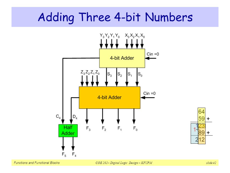
Adding Three 4-bit Numbers
Problem: Add three 4-bit numbers (X, Y, Z) using standard MSI combinational components Solution: Let the numbers be X3X2X1X0, Y3Y2Y1Y0, Z3Z2Z1Z0 X3X2X1X0 + Y3Y2Y1Y0 C4 S3S2S1S0 S3S2S1S0 Z3Z2Z1Z0 D4 F3F2F1F0 Note: C4 and D4 are generated in position 4. They must be added to generate the most significant bits of the result
 using standard MSI combinational components. Solution: Let the numbers be X3X2X1X0, Y3Y2Y1Y0, Z3Z2Z1Z0. X3X2X1X0. + Y3Y2Y1Y C4 S3S2S1S0. S3S2S1S0. + Z3Z2Z1Z D4 F3F2F1F0. Note: C4 and D4 are generated in position 4. They must be added to generate the most significant bits of the result.")
42
Adding Three 4-bit Numbers
64 59 + 123 89 + 212 1
43
Adding Two 16-bit Numbers using 4-bit Adders
Solution: Four 4-bit adder blocks are connected in cascade, with carries rippling in between

44
Design a 4-to-16 Decoder Using 2-to-4 Decoders with Enable
Problem: Design a 4x16 Decoder using 2x4 Decoders Solution: Each group combination holds a unique value for A3A2 One Decoder can be therefore used with inputs: A3A2 Four more decoders are needed for representing each individual color combination Select 1 of the 4 2-to-4 decoders Common to all 4 3-to-4 decoders A3 A2 A1 A0 Active Output D0 1 D1 D2 D3 D4 D5 D6 D7 D8 D9 D10 D11 D12 D13 D14 D15 A3A2 = 00 A3A2 = 01 A3A2 = 10 A3A2 = 11

45
Design a 4-to-16 Decoder Using 2-to-4 Decoders with Enable
2x4 Decoder D0 D1 D2 D3 A0 A1 E 2x4 Decoder D4 D5 D6 D7 A0 A1 D0 D1 D2 D3 A2 A3 2x4 Decoder 2x4 Decoder D8 D9 D10 D11 A0 A1 Enable for the full 4-to16 decoder E 2x4 Decoder D12 D13 D14 D15 A0 A1

46
Hardware that Compares Two Unsigned 4-bit Numbers and Passes the Larger of the Two
Solution: We will use a magnitude comparator and a Quad 2-to-1 MUX. How?

47
BCD to Excess-3 Code Converter using a Decoder and Straight Binary Encoder
Index 1 2 3 4 5 6 7 8 9 BCD: 0 - 9 Excess-3:

Similar presentations
 Half-adder adds rightmost (least significant) bit Full-adder.>")


 – –a fixed array of AND gates.>")


 Chapter 3 – Combinational Logic Design Part 2 –>")


 Terms of Use Logic and Computer Design.>")
