Download presentation
Presentation is loading. Please wait.

1
Turbomachinery Turbo : latin prefix, means spin
Energy is extracted or supplied by a rotating shaft Not all pumps use rotating shaft so we can call them fluid machine ( nowadays turbomachine is used for all )
")
2
Pump: adds energy to a fluid, resulting in an increase in pressure
( not necessarily increase in velocity) across the pump. Turbine: extracts energy from the fluid, resulting in a decrease in pressure (not necessarily decrease in velocity) across the turbine.
 across the pump. Turbine: extracts energy from the fluid, resulting in a decrease in pressure. (not necessarily decrease in velocity) across the turbine.")
3
General comments on the pipeline design
ease and cost of pumping=f(Design of pipeline ) -Design piping to minimize energy requirement of pumping ( especially energy losses due to friction and shock losses) -Keep the total length of pipeline as short as possible
 -Design piping to minimize energy requirement of pumping ( especially energy losses due to friction and shock losses) -Keep the total length of pipeline as short as possible.")
4
maintain same pipe diameter, if changes are unavoidable use reducing or expanding unions rather than abrupt changes in diameter Use the correct type and minimum number of fittings. avoid using gate valve ( on-off valve) to regulate flow rate Then select a suitable pump
 to regulate flow rate. Then select a suitable pump.")
5
Factors influencing the choice of the pump
1- The quantity of liquid to be handled: affects the size and type of the pump, determines if parallel pumps needed. 2- The head against which the liquid is to be pumped. determined by the difference in pressure and velocity, the vertical height of the downstream and upstream reservoirs and by the frictional losses which occur in the delivery line. The suitability of a centrifugal pump and the number of stages required will largely be determined by this factor ( as D decreases, v increases, energy loss increases in turn expensive pumping….so optimum pipe diameter must be selected)
")
6
3- The nature of the liquid to be pumped.
a) consistency ( viscosity) the viscosity largely determines the frictional losses and hence the power required b) density c) temperature ( effects viscosity, pump material, cavitation ) d) corrosive and/or erosive nature of fluid (The corrosive nature will determine the material of construction .With suspensions, the clearance in the pump must be large compared with the size of the particles.) e)shear deformation( fluid flow characteristic and crystal habbit may change under high shear) e) lubricating properties of fluid ( for all metal rotary pumps requires fluid to be lubricant)
 consistency ( viscosity) the viscosity largely determines the frictional losses and hence the power required. b) density. c) temperature ( effects viscosity, pump material, cavitation ) d) corrosive and/or erosive nature of fluid (The corrosive nature will determine the material of construction .With suspensions, the clearance in the pump must be large compared with the size of the particles.) e)shear deformation( fluid flow characteristic and crystal habbit may change under high shear) e) lubricating properties of fluid ( for all metal rotary pumps requires fluid to be lubricant)")
7
4- The nature of power supply
4- The nature of power supply. ( though most pumps are coupled to electric motors either directly or via pulleys and v-belts’ reciprocating pumps can be also actuated by steam or compressed air) 5- hygenic requirements. In the food industry contamination must be quarded against all times
 5- hygenic requirements. In the food industry contamination must be quarded against all times.")
8
Categories Fans, Blowers, and Compressors
Fans: Low pressure gradient, High volume flow rate. Examples include ceiling fans and propellers. Blower: Medium pressure gradient, Medium volume flow rate. (ie centrifugal blowers found in furnaces, leaf blowers, and hair dryers.) Compressor: High pressure gradient, Low volume flow rate. (ie air compressors for air tools, refrigerant compressors for refrigerators)
 Compressor: High pressure gradient, Low volume flow rate. (ie air compressors for air tools, refrigerant compressors for refrigerators)")
9
Fans: ΔP = from 2 or 3” of water up to about 0.5 psi. classified into three types: The propeller type : electric fan Plate fan : 8 to 12 plate steel blades inside a casing. (ΔP from 0 to 5” water) If blades curved : ΔP up to 27” water. The multi-blade fans ΔP from 0 to 5” water. ( much higher efficiencies and deliver much larger volumes for a given size of drum than steel-plate fans.)
 If blades curved : ΔP up to 27 water. The multi-blade fans ΔP from 0 to 5 water. ( much higher efficiencies and deliver much larger volumes for a given size of drum than steel-plate fans.)")
10
Blowers: Any pump of the rotary type can be used as a blower ( two or three lobes) ΔP from 0.5 to 10 psi. The appearance of centrifugal blower resembles a centrifugal pump, except that the casing is narrower and larger impeller diameter. The operating speed ≥ 3000 rpm.

11
Compressors: process gas - up to 100 m3/sec at the inlet - to an outlet pressure of 20 atm. ( smaller capacity up to several hundred atms. ) cooling is needed on the high pressure units. Axial flow machines :up to 300 m3/sec, press of 2 to 10 atm. Rotary positive displacement compressors: press to 6 atm. Most compressors operating at discharge press above 3 atm are reciprocating positive displacement machines. If required compression ratio is greater than that can be achieved in one cylinder, multistage compressors are used. The maximum pressure ratio normally obtained in a single cylinder is 10 atm but values above 6 are unusual
 cooling is needed on the high pressure units. Axial flow machines :up to 300 m3/sec, press of 2 to 10 atm. Rotary positive displacement compressors: press to 6 atm. Most compressors operating at discharge press above 3 atm are reciprocating positive displacement machines. If required compression ratio is greater than that can be achieved in one cylinder, multistage compressors are used. The maximum pressure ratio normally obtained in a single cylinder is 10 atm but values above 6 are unusual.")
12
Airflow through a centrifugal air compressor

13
PUMPS Positive displacement Centrifugal, dynamic, kinetic
Reciprocating Rotary -piston -diaphram -Helical screw -gear -lobe -peristaltic

14
Categories Positive-displacement machines
Closed volume is used to squeeze or suck fluid. Pump: human heart Turbine: home water meter

15
line since over pressure can develop.
All PD pumps not be allowed to pump against a closed delivery line since over pressure can develop. A pressure relief valve should be incorporated in the discharge line to allow controlled release of any excessive pressure through mal operation.

16
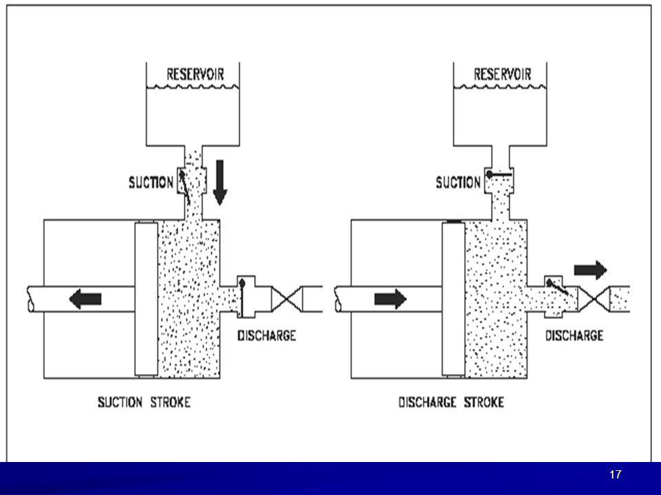
Reciprocating PD pumps
PISTON pumps -single cylinder( pulsating flow) -multi cylinder( smoother flow) -can handle high µ -develop high ΔP -don’t use with abrasive fluids -delivers accurately known volumes so used as metering pump
 -multi cylinder( smoother flow) -can handle high µ. -develop high ΔP. -don’t use with abrasive fluids. -delivers accurately. known volumes so. used as metering pump.")
18
Diaphragm pump Simple Limited ΔP development
Check valves had to be used Inexpensive Able to handle corrosive and abrasive fluids Fluid is not in contact with most of the moving parts

19
Rotary PD pumps

20
HELICAL SCREW pump Can handle very high pressure Abrasive liquids can be run Should not be run dry Ie. Extruders in food production

21
Gear pumps External gear pump
As # of teeth inreases flow gets smoother develop high ΔP (up to 200 bar ) don’t use with abrasive fluids High shear
 don’t use with abrasive fluids. High shear.")
22
Internal gear PD pumps -develop high ΔP (up to 200 bar )
Gentler than external gear PD More expensive and complicated

23
lobe pump - can deliver total heads of 20 bar. - easy to clean
- can transfer fluid at flowrates up to 500 m3/hr - can deliver total heads of 20 bar. - easy to clean can handle shear sensitive products Most widely used PD pump for food aplications

24
Peristaltic Pump most hygenic pump available)
can generate heads of up to 5m at flows of up to 10 m3/hr. -most gentle : Fragile blood cells are not damaged by this pump. Orange segments, wallnut pieces can be transferred. (another application: The EnTire Self-Inflating Tire system)
")
25
High velocity creates vacuum
Jet pumps: Bernoulli’s principle no moving parts hin + vin2/ = hout + vout2/2 High velocity creates vacuum

26
Air lift pump Air is injected to the bottom of the vertical pipe.
The specific gravity of the water inside the pipe becomes less than that outside the pipe. This difference transfers the liquid upward in the pipe. simple used for petroleum, handling of hazardous fluids, the design of bioreactors, recycle aeration in sludge digesters. Air lift pump

27
Geyser pump Geyser Pump was invented in 1999
Geyser Pump was developed to overcome weak points of airlift pump.

28
Following weekneses of airlift pump is prevented

30
Dynamic machines (centrifugal, kinetic)
No closed volume. Instead, rotating blades supply or extract energy. Enclosed/Ducted Pumps: torpedo propulsor Open Pumps: propeller or helicopter rotor

31
Enclosed Turbines: hydroturbine
Open Turbines: wind turbine

32
The faster you spin, the more water comes out the small hole, the water is pressurized inside the cup using centrifugal force in a similar fashion to a centrifugal pump.

33
How to select a centrifugal pump
expected to deliver exactly the flow rate you require. The flow rate =f( physical characteristics of your system such:length,size of the pipes, elevation difference ) The pump manufacturer has no means of knowing what these constraints will be. This is why buying a centrifugal pump is more complicated than buying a positive displacement pump which will provide its rated flow no matter what system you install it in.
 The pump manufacturer has no means of knowing what these constraints will be. This is why buying a centrifugal pump is more complicated than buying a positive displacement pump which will provide its rated flow no matter what system you install it in.")
34
Dynamic Pumps include centrifugal pumps: fluid enters axially, and is discharged radially. mixed--flow pumps: fluid enters axially, and leaves at an angle between radially and axially. axial pumps: fluid enters and leaves axially.

35
Centrifugal Pumps Snail--shaped scroll
Most common type of pump: homes, autos, industry.

36
Centrifugal Pumps

37
Centrifugal Pumps: Blade Design

38
Pump Head Net Head Water horsepower( useful energy actually delivered to fluid) Brake horsepower ( energy supplied to pump) Pump efficiency

39
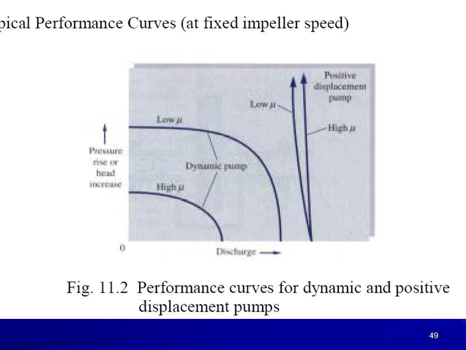
Matching a Pump to a Piping System
Pump-performance curves for a centrifugal pump (H=f(V), bhp=f(V), η=f(V)) BEP: best efficiency point H*, bhp*, V* correspond to BEP Shutoff head: achieved by closing outlet (V=0), At this point η=0( no flow) Free delivery: no load on system (Hrequired = 0) At this point η=0( pump is not doing any work)
, bhp=f(V), η=f(V)) BEP: best efficiency point. H*, bhp*, V* correspond to BEP. Shutoff head: achieved by closing outlet (V=0), At this point η=0( no flow) Free delivery: no load on system (Hrequired = 0) At this point η=0( pump is not doing any work)")
40
Discharge pressure =( suction press+press developed by the pump)
Suction pressure : the pressure at the pump’s suction nozzle. (most imp. press inside the pump. ) If the suction pressure is inadequate, it leads to cavitation. pumps need a gauge at the suction nozzle to measure the pressure entering the pump. Discharge pressure =( suction press+press developed by the pump) Press. at the pump discharge nozzle as measured by a gauge.
 If the suction pressure is inadequate, it leads to cavitation. pumps need a gauge at the suction nozzle to measure the pressure entering the pump. Discharge pressure =( suction press+press developed by the pump) Press. at the pump discharge nozzle as measured by a gauge.")
41
Flow rate depends on elevation difference or static head his velocity will be moderate and correspond to the amount of energy he can supply to overcome the friction of the wheels on the road and the change in elevation

42
Negative static head increase flow rate.

43
High static head decreases flow rate.

45
Flow rate is limited by friction in the system when the static head is zero.

46
Suction head Suction lift Discharge head Total head

50
Matching a Pump to a Piping System
Steady operating point: Energy equation:

51
If we are lucky operating point is at or near BEP of pump
If we are lucky operating point is at or near BEP of pump. In most cases pumps do not run at their optimum efficiency If eff is a major concern, Select a new pump such that operating point as close as to BEP point We can reach this sometimes by changing rotational speed The most common situation is that an engineer selects a pump heftier( more powerful) than actually required. So volumetric flow rate will be larger than needed, a valve or a damper is used to decrease the flow rate to desired level
 than actually required. So volumetric flow rate will be larger than needed, a valve or a damper is used to decrease the flow rate to desired level.")
52
What is the pump rating? The manufacturer will rate the pump at its optimum total head and flow, this point is also known as the best efficiency point or B.E.P. At that flow rate: most efficient, minimal vibration and noise. the life of the pump will suffer if you operate too far away from its normal rating. As a guideline, aim for a variation of plus or minus 15% on total head.

53
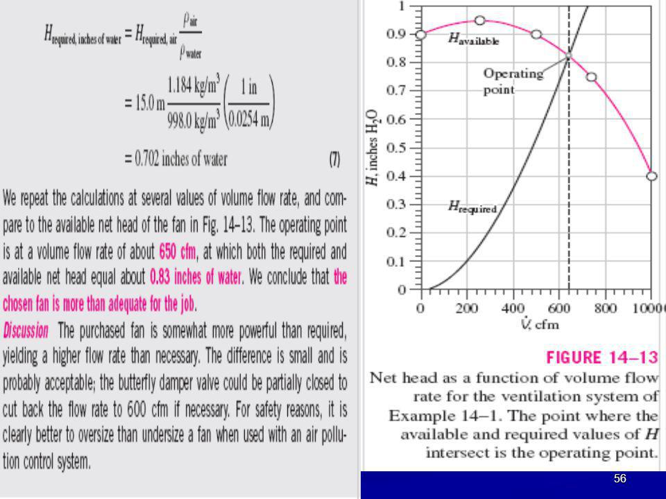
Operating Point of a Fan in a Ventilation System
A local ventilation system (hood and exhaust duct) is used to remove air and contaminants produced by a dry-cleaning operation . The duct is round and is constructed of galvanized steel with longitudinal seams and with joints every 30 in (0.76 m). ID of the duct is D 9.06 in (0.230 m), its total length is L ft (13.4 m). There are five CD3-9 elbows along the duct. The equivalent roughness of this duct is 0.15 mm, and each elbow has a minor (local) loss coefficient of KL C the minimum required volume flow rate through the duct is V 600 cfm, or m3/s at 25C. hood entry loss coefficient as 1.3 based on duct velocity. When the damper is fully open, its loss coefficient is 1.8. A centrifugal fan with 9.0-in inlet and outlet diameters is available. Its performance data are shown in Table 14–1, as listed by the manufacturer. Predict the operating point of this local ventilation system, and draw a plot of required and available fan pressure rise as functions of volume flow rate Is the chosen fan adequate?
 is used to remove air and contaminants produced. by a dry-cleaning operation . The duct is round and is constructed of galvanized. steel with longitudinal seams and with. joints every 30 in (0.76 m). ID of the duct is D 9.06 in (0.230 m), its total length is L 44.0 ft (13.4 m). There are five CD3-9. elbows along the duct. The equivalent roughness. of this duct is 0.15 mm, and each elbow has a minor (local) loss coefficient of KL C the minimum required volume flow rate through the duct. is V 600 cfm, or m3/s at 25C. hood entry loss coefficient as 1.3 based on duct velocity. When the damper is fully open, its loss coefficient is 1.8. A centrifugal fan with 9.0-in inlet and outlet diameters is. available. Its performance data are shown in Table 14–1, as listed by the manufacturer. Predict the operating point. of this local ventilation system, and draw a plot of required. and available fan pressure rise as functions of volume. flow rate Is the chosen fan adequate")
54
P1=P2=Patm , v1=0 , z2-z1=0

57
Selection of Pump Impeller Size
A washing operation at a power plant requires 370 gallons per minute (gpm) of water. The required net head is about 24 ft at this flow rate. A newly hired engineer looks through some catalogs and decides to purchase the 8.25-in impeller option of the Taco Model 4013 FI Series centrifugal pump of Fig. 14–15. If the pump operates at 1160 rpm, as specified in the performance plot, she reasons, its performance curve intersects 370 gpm at H 24 ft. The chief engineer, who is very concerned about efficiency, glances at the performance curves and notes that the efficiency of this pump at this operating point is only 70 percent.
 of water. The required net head is about 24 ft at this flow rate. A newly hired engineer looks through some catalogs and decides to purchase the 8.25-in impeller option of the Taco Model 4013 FI Series centrifugal pump of Fig. 14–15. If the pump operates at 1160 rpm, as specified in the performance plot, she reasons, its performance curve intersects 370 gpm at H 24 ft. The chief engineer, who is very concerned about efficiency, glances at the performance curves and notes that the efficiency of this pump at this operating point is only 70 percent.")
58
He sees that the in impeller option achieves a higher efficiency (about 76.5 percent) at the same flow rate. He notes that a throttle valve can be installed downstream of the pump to increase the required net head so that the pump operates at this higher efficiency. He asks the junior engineer to justify her choice of impeller diameter. Namely, he asks her to calculate which impeller option (8.25-in or in) would need the least amount of electricity to operate (Fig. 14–16). Perform the comparison and discuss.
 would need the least amount of electricity to operate (Fig. 14–16). Perform the comparison and discuss.")
60
Manufacturer Performance Plot
1160 rpm, 370 gpm, 8.25” impeller diameter corresponds, bhp, head 24 ft, η=70% 1160 rpm,370 gpm,12.75 “impeller diameter corresponds, 8.78 bhp, head 72 ft, η=76.5%

62
Cavitation can be termed as “the heart attack of the pump”.

63
Pump Cavitation and NPSH
Cavitation should be avoided due to erosion damage and noise. Cavitation occurs when P < Pv Net positive suction head NPSHrequired curves are created through systematic testing over a range of flow rates V.

64
Definition NPSHa (available)
This is the energy in the fluid at the suction connection of the pump over and above the liquid’s vapor pressure. It is a characteristic of the system and we say that the NPSHa should be greater than the NPSHr (NPSHa > NPSHr +3 ft).
.")
65
Definition of NPSHr (required)
It is a characteristic of the pump and is indicated on the pump's curve. It varies by design, size, and the operating conditions An easy way to understand NPSHr is to call it the minimum suction pressure necessary to keep the pumped fluid in a liquid state. According to the Standards of the Hydraulic Institute, a suction lift test is performed on the pump and the pressure in the suction vessel is lowered to the point where the pump suffers a 3% loss in total head. This point is called the NPSHr of the pump.

66
To increase NPSHa 1- raise the level in the suction vessel
2- elevate the suction vessel 3- lower the pump 4-reduce the friction in the suction piping 5-lower the temp of the fluid in the suction vessel 6-pressurise the suction vessel

67
(EXAMPLE) Maximum Flow Rate to Avoid Pump Cavitation
The in impeller option of the Taco Model 4013 FI Series centrifugal pump of Fig. 14–15 is used to pump water at 25C from a reservoir whose surface is 4.0 ft above the centerline of the pump inlet. The piping system from the reservoir to the pump consists of 10.5 ft of cast iron pipe with an ID of 4.0 in and an average inner roughness height of 0.02 in.

68
There are several minor losses:
a sharp-edged inlet (KL 0.5), three flanged smooth 90 regular elbows (KL 0.3 each), and a fully open flanged globe valve (KL 6.0). Estimate the maximum volume flow rate (in units of gpm) that can be pumped without cavitation. If the water were warmer, would this maximum flow rate increase or decrease? Why? Discuss how you might increase the maximum flow rate while still avoiding cavitation.
, three flanged smooth 90 regular elbows (KL 0.3 each), and a fully open flanged globe valve (KL 6.0). Estimate the maximum volume flow rate (in units of gpm) that can be pumped without cavitation. If the water were warmer, would this maximum flow rate increase or decrease Why Discuss how you might increase the maximum flow rate while still avoiding cavitation.")
69
At 400gpm NPSHr=4 ft

70
Assumptions 1 The flow is steady. 2 The liquid is incompressible.
Properties For water at T = 25 C, ρ =997.0 kg/m3, µ=8.91x10⁻⁴ kg/m·s, and Pv= kPa. Standard atmospheric pressure is Patm kPa. We apply the steady energy equation in head form along a streamline from point 1 at the reservoir surface to point 2 at the pump inlet,

71
Insert eq 2 Since we know Patm, Pv, and the elevation difference, all that remains is to estimate the total irreversible head loss through the piping system, which depends on volume flow rate. Since the pipe diameter is constant, For a given volume flow rate, we calculate speed V and Reynolds number Re. From Re and the known pipe roughness, we use the Moody chart (or the Colebrook equation) to obtain friction factor f The sum of all the minor loss coefficients is
 to obtain friction factor f. The sum of all the minor loss coefficients is.")
72
Since the actual NPSH is much higher than this, we need not worry about cavitation at
this flow rate. We use a spreadsheet to calculate NPSH as a function of volume flow rate, and the results are plotted in Fig. 14–21. It is clear from this plot that at 25C, cavitation occurs at flow rates above approximately 602 gpm—close to the free delivery.

73
If the water were warmer than 25C, the vapor pressure would increase, the viscosity would decrease, and the density would decrease slightly. where we see that the maximum volume flow rate without cavitation decreases with temperature (to about 555 gpm at 60C). This decrease agrees with our intuition, since warmer water is already closer to its boiling point from the start.
. This decrease agrees with our intuition, since warmer water is already closer to its boiling point from the start.")
74
General Symptoms of Cavitation
and its Affects on Pump Performance and Pump Parts Reduction in capacity of the pump: The formation of bubbles causes a volume increase decreasing the space available for the liquid and thus diminish pumping capacity. (when water changes state from liquid to gas its volume increases by approximately 1,700 times.

75
Decrease in the head developed:
Bubbles are compressible. The head developed diminishes drastically because energy has to be expended to increase the velocity of the liquid used to fill up the cavities, as the bubbles collapse. The Hydraulic Standards Institute defines cavitation as condition of 3 % drop in head developed across the pump

76
Abnormal sound and vibrations:
It is movement of bubbles with very high velocities from low-pressure area to a high-pressure area and subsequent collapse that creates shockwaves producing abnormal sounds and vibrations. It has been estimated that during collapse of bubbles the pressures of the order of 104 atm develops. The sound of cavitation can be described as similar to small hard particles or gravel rapidly striking or bouncing off the interior parts of a pump or valve.

77
To distinguish between the noise due to a bad bearing or cavitation, operate the pump with no flow. The disappearance of noise will be an indication of cavitation. The excessive vibration caused by cavitation often subsequently causes a failure of the pump’s seal and/or bearings. This is the most likely failure mode of a cavitating pump

78
Damage to pump parts:Cavitation erosion or pitting
During cavitation, the collapse of the bubbles occurs at sonic speed ejecting destructive micro jets of extremely high velocity (up to 1000 m/s) liquid strong enough to cause extreme erosion of the pump parts, particularly impellers. High head pumps are more likely to suffer from cavitation erosion. The most sensitive areas where cavitation erosion has been observed are the low-pressure sides of the impeller vanes near the inlet edge.
 liquid strong enough to cause extreme erosion of the pump parts, particularly impellers. High head pumps are more likely to suffer from cavitation erosion. The most sensitive areas where cavitation erosion has been observed are the low-pressure sides of the impeller vanes near the inlet edge.")
79
Mechanical deformations
longer duration of cavitation condition can result in unbalancing (due to un-equal distribution in bubble formation and collapse) of radial and axial thrusts on the impeller. leads to following mechanical problems: · bending and deflection of shafts, · bearing damage and rubs from radial vibration, · thrust bearing damage from axial movement, · breaking of impeller check-nuts, · seal faces damage etc.
 of radial and axial thrusts on the impeller. leads to following mechanical problems: · bending and deflection of shafts, · bearing damage and rubs from radial vibration, · thrust bearing damage from axial movement, · breaking of impeller check-nuts, · seal faces damage etc.")
81
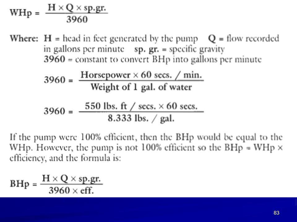
We say that the motor generates horsepower (HP), and that the pump consumes brake horsepower (BHp).
The difference between HP (output) and BHp (input) is what is lost in the power transmission; the bearings, shaft, and coupling between the motor and the pump
 and BHp (input) is what is lost in the power transmission; the bearings, shaft, and coupling between the motor and the pump.")
82
PUMP EFFICIENCY

84
the practical applications centrifugal pumps
The pump curve, the H-Q curve, is in a descending profile. Q and H changes irreversibly At times, in normal industrial production, the flow must rise and fall, but the pressure or head must remain a constant. Many industrial processes experience seasonal rises and falls. This means that flow varies.

85
The pasteurization process for milk and ice cream requires heating the milk to a specified temperature and pressure for a specified time to kill all germs and bacteria in the milk. This pressure is constant although the production of milk and ice cream goes up and down with consumption and the seasonal changes.

86
sterile water production to prepare medications for injection.
require boiling the water at 35 psi, and pumping the water at 40 gpm to 70 gpm, according to consumption. The 35 psi is a constant pressure needed for the water to pass through the heat exchanger, and a bank of filters. by varying the diameter of the impeller, so that the pump can pump 40 gpm at 35 psi, or 50 gpm at 35 psi, or 70 gpm at 35 psi. This allows the operator to use the same pump and motor, and only change the impeller diameter depending on the needs of production.

87
This precise manipulation of pumping parameters could not be obtained by opening and closing valves
A pump consuming 10 BHP with a 10 inch impeller, would only consume 7.3 horses with a 9 inch impeller. This means a 10% reduction in the impeller diameter, would bring about almost 30% reduction in energy. These energy savings will easily cover the cost of multiple impellers and the manpower to change them frequently.

88
PARALLEL PUMPS

89
PUMPS IN SERIES

90
The third pump will not be able to open the check valve with two pumps keeping it closed. So in practice, you can operate any one pump, or any two pumps, or four pumps, but not three pumps. (12 gate valves and 2 check valves exist)
.")
91
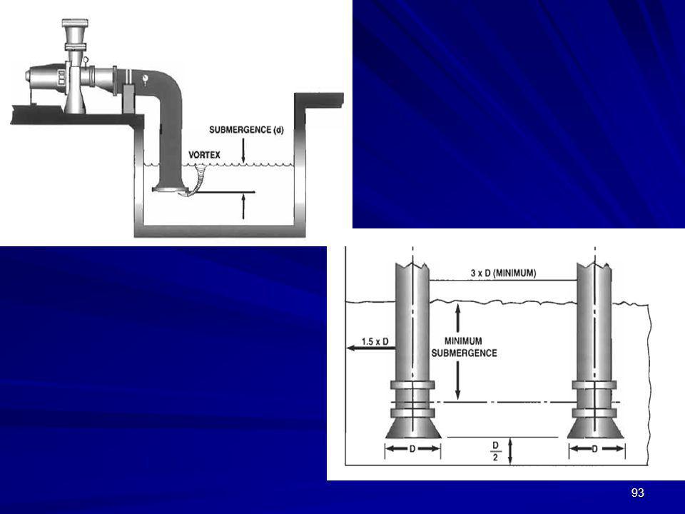
Pump Piping

92
Level indicator. Inadequate design , bubbles entrained

94
Prefer Y branch rather than T to reduce turbulent

95
Use an eccentric pipe reducer

Similar presentations


 Grants Chapter 6.>")


 Motion Controller Design for A Class of Second-order Systems Center for Self-Organizing Intelligent.>")
>")

