Download presentation
Presentation is loading. Please wait.

1
Refrigeration Cycles د/ محمود عبدالوهاب

2
The vapor compression refrigeration cycle is a common method for transferring heat from a low temperature to a high temperature.

3
The above figure shows the objectives of refrigerators and heat pumps
The above figure shows the objectives of refrigerators and heat pumps. The purpose of a refrigerator is the removal of heat, called the cooling load, from a low-temperature medium. The purpose of a heat pump is the transfer of heat to a high-temperature medium, called the heating load. When we are interested in the heat energy removed from a low-temperature space, the device is called a refrigerator. When we are interested in the heat energy supplied to the high-temperature space, the device is called a heat pump. In general, the term heat pump is used to describe the cycle as heat energy is removed from the low-temperature space and rejected to the high-temperature space.

4
The performance of refrigerators and heat pumps is expressed in terms of coefficient of performance (COP), defined as Both COPR and COPHP can be larger than 1. Under the same operating conditions, the COPs are related by

5
SEER = COP * 3.4122 1 TR = 12000 Btu/hr = 3.517 kW
Can you show this to be true? Refrigerators, air conditioners, and heat pumps are rated with a SEER number or seasonal adjusted energy efficiency ratio. The SEER is defined as the Btu/hr of heat transferred per watt of work energy input. The Btu is the British thermal unit and is equivalent to 778 ft-lbf of work (1 W = Btu/hr). An SEER of 10 yields a COP of 2.9. SEER = COP * Refrigeration systems are also rated in terms of tons of refrigeration. One ton of refrigeration is equivalent to 12,000 Btu/hr or 211 kJ/min. How did the term “ton of cooling” originate? 1 TR = Btu/hr = kW
. An SEER of 10 yields a COP of 2.9. SEER = COP * Refrigeration systems are also rated in terms of tons of refrigeration. One ton of refrigeration is equivalent to 12,000 Btu/hr or 211 kJ/min. How did the term ton of cooling originate 1 TR = Btu/hr = kW.")
6
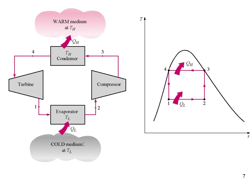
Reversed Carnot Refrigerator and Heat Pump
Shown below are the cyclic refrigeration device operating between two constant temperature reservoirs and the T-s diagram for the working fluid when the reversed Carnot cycle is used. Recall that in the Carnot cycle heat transfers take place at constant temperature. If our interest is the cooling load, the cycle is called the Carnot refrigerator. If our interest is the heat load, the cycle is called the Carnot heat pump.

8
The standard of comparison for refrigeration cycles is the reversed Carnot cycle. A refrigerator or heat pump that operates on the reversed Carnot cycle is called a Carnot refrigerator or a Carnot heat pump, and their COPs are

9
Notice that a turbine is used for the expansion process between the high and low-temperatures. While the work interactions for the cycle are not indicated on the figure, the work produced by the turbine helps supply some of the work required by the compressor from external sources. Why not use the reversed Carnot refrigeration cycle? Easier to compress vapor only and not liquid-vapor mixture. Cheaper to have irreversible expansion through an expansion valve. What problems result from using the turbine instead of the expansion valve?

10
The Vapor-Compression Refrigeration Cycle
The vapor-compression refrigeration cycle has four components: evaporator, compressor, condenser, and expansion (or throttle) valve. The most widely used refrigeration cycle is the vapor-compression refrigeration cycle. In an ideal vapor-compression refrigeration cycle, the refrigerant enters the compressor as a saturated vapor and is cooled to the saturated liquid state in the condenser. It is then throttled to the evaporator pressure and vaporizes as it absorbs heat from the refrigerated space.
 valve. The most widely used refrigeration cycle is the vapor-compression refrigeration cycle. In an ideal vapor-compression refrigeration cycle, the refrigerant enters the compressor as a saturated vapor and is cooled to the saturated liquid state in the condenser. It is then throttled to the evaporator pressure and vaporizes as it absorbs heat from the refrigerated space.")
11
The Vapor-Compression Refrigeration Cycle
The ideal vapor-compression cycle consists of four processes. Ideal Vapor-Compression Refrigeration Cycle Process Description 1-2 Isentropic compression 2-3 Constant pressure heat rejection in the condenser 3-4 Throttling in an expansion valve 4-1 Constant pressure heat addition in the evaporator

12
The following diagrams, show the flow and T-s diagram illustrates the refrigeration cycle.

13
The P-h diagram is another convenient diagram often used to illustrate the refrigeration cycle.

14
The ordinary household refrigerator is a good example
of the application of this cycle.

15
Thermodynamic analysis of ideal vapor-compression cycle “ SSVCC” “ simple saturation vapor compression refrigeration cycle

16
Relative efficiency Refrigerator relative efficiency is defined as the ratio between the actual refrigeration cycle coefficient of performance and that for Carnot cycle at same heat source and heat sink temperatures. hR =

17
Definitions Refrigeration capacity: is the amount of heat transfer to the evaporator in kW; for steady operations the refrigeration capacity equal to the refrigeration load Refrigeration effect: the amount of heat transfer to the evaporator per one kg of refrigerant mass flow rate through it " kJ/kg" Condenser duty: is the amount of heat transfer from condenser to surroundings in kW Compressor indicated power: is power added to the refrigerant during compression process ;kW Compressor brake power: the power required to brake the compressor kW; compressor brake power greater than the compressor indicate power" defined the compressor mechanical efficiency"

18
Example 1 Refrigerant-134a is the working fluid in an ideal compression refrigeration cycle. The refrigerant leaves the evaporator at -20oC and has a condenser pressure of 0.9 MPa. The mass flow rate is 3 kg/min. Find COPR and COPR, Carnot for the same Tmax and Tmin , and the refrigeration capacity in tons of refrigeration. Using the Refrigerant-134a Tables, we have

20
The tons of refrigeration, often called the cooling load or refrigeration effect, are

21
Another measure of the effectiveness of the refrigeration cycle is how much input power to the compressor, in horsepower, is required for each ton of cooling. The unit conversion is hp per ton of cooling. Find the system SEER?

22
heat transfer to or from the surroundings.
ACTUAL VAPOR-COMPRESSION REFRIGERATION CYCLE An actual vapor-compression refrigeration cycle differs from the ideal one in several ways, owing mostly to the irreversibilities that occur in various components, mainly due to fluid friction (causes pressure drops) and heat transfer to or from the surroundings. The COP decreases as a result of irreversibilities.
 and. heat transfer to or from the surroundings. The COP decreases as a result of irreversibilities.")
23
ACTUAL VAPOR-COMPRESSION REFRIGERATION CYCLE
Schematic and T-s diagram for the actual vapor-compression refrigeration cycle.

24
The difference between actual and simple refrigeration cycles are:
ACTUAL VAPOR-COMPRESSION REFRIGERATION CYCLE DIFFERENCE: The difference between actual and simple refrigeration cycles are: 1- Non-isentropic compression 2- Superheated vapor at evaporator exit 3- Sub-cooled liquid at condenser exit 4- Pressure drops in condenser and evaporator 5- pressure drop in suction and discharge valves. 6- refrigerant heating during suction stroke.

25
Compressor isentropic efficiency Polytrophic power
ACTUAL VAPOR-COMPRESSION REFRIGERATION CYCLE Compressor isentropic efficiency Polytrophic power Pressure drop in suction and discharge valves Refrigerant heating during suction process. Actual volumetric efficiency

26
Reciprocating compressors

29
Single acting Clearance volumetric efficiency=

30
Apparent “clearance” volumetric efficiency
Clearance ratio C = clearance volume/ swept volume Clearance volume = volume above the top dead center = Vc Swept volume = volume of the cylinder between top and bottom dead centers = volume above the bottom dead center - volume above the top dead center

31
P Pd PS VC V V2

32
Actual volume = volume above bottom dead center – volume of residual gages after expansion from discharge to suction pressure = V2 – V1 Theoretical volume = swept volume = volume above bottom dead center - volume above top dead center = V2 - Vc Clearance ratio C = clearance volume / swept volume = Vc / (V2 – V1)
")
33
Volumetric efficiency =

35
Compressor power Compressors are classified into the following categories from Th.D. point of view 1- isentropic compressors “ Adiabatic + reversible” Q =0 and no internal and external irreversibleness S = constant IW isent = m ref Dh isent 2- Adiabatic compressors, Q= 0 and DS 0 IW adiab = m ref Dh act. Compressor efficiency = compressor isentropic efficiency = IW isent / IW adiab = Dh isent / Dh act

36
Compressor power 3- poly-tropic compressors
During the compression process the refrigerant follows the relation Pv n = constant = C Since the indicated work is given as

37
Compressor power Since,

38
Heat transfer to poly-tropic compressor
Find the rate of heat transfer to the poly-tropic compressor?

39
Heat Pump Systems

Similar presentations


.>")
