Download presentation
Presentation is loading. Please wait.

1
Basics of Supercritical Steam Generators
P M V Subbarao Professor Mechanical Engineering Department I I T Delhi Thermodynamically Obvious Choice but …. Why Aren’t There More Supercritical Units?

2
Reheat Supercritical Rankine Cycle
3 5 2s 4 2 6 1

3
Double Reheat Ultra Super Critical Cycle
8

4
Historical Development in Steam Generators
Furnace Heat Release Rate

5
Effect of Boiler Steam Conditions on Net Plant Efficiency
250bar 565/5900C 250bar 565/5650C 250bar 556/5650C 170bar 556/5560C 250bar 556/5560C

6
Towards Matured & Sustainable SC Technology

7
Why So Late? If supercritical units are more efficient supercritical the right answer for any new coal-fired unit? First, there is history. Most coal-fired plants in the World are subcritical. Second, initial supercritical units suffered more from the rapid increase in unit size than from technology. Supercritical systems demanded considerable advances in design and operation . Heavy Slagging: Undersized furnace and inadequate coverage by soot blowing system. Circumferential cracking of waterwall tubes: High Metal Temperatures. Frequents requirement of acid cleaning. Low Availability and Reliability. Lower efficiency than expected.

8
Historical trend of furnace heat release rates for coal-fired boilers

9
Expectations from Steam Generator for Higher Efficiency
High Main Steam Pressure. High Main Steam Temperature. Double Reheat & Higher Regeneration. Metal component strength, stress, and distortion are of concern at elevated temperatures in both the steam generator and the steam turbine. In the steam generator’s heating process, the tube metal temperature is even higher than that of the steam, and concern for accelerated corrosion and oxidation will also influence material selection.

10
Role of SG in Rankine Cycle
Perform Using Natural resources of energy …….

11
Thermal Structure of A SG
DPNL SH Platen SHTR R H T LTSH Economiser APH ESP ID Fan drum Flame BCW pump Bottom ash stack screen tubes

12
The Basics of Flow Boiling….

13
Boiling process in Tubular Geometries
Heat Input Water Steam Partial Steam Generation Complete or Once-through Generation Water

14
Religious to Secular Attitude

15
Flow Boiling

16
Tube Wall Temperature : Sub-critical Flow Boiling
Newton’s Law of Cooling:

17
Heat Transfer in Flow Boiling

18
Auto Control Mechanism in Natural Circulation

19
Religious to Secular Attitude

20
Tube Wall Temperature : Super-critical Flow Boiling
Newton’s Invention:

21
Heat Transfer in Liquid Region
The liquid in the channel may be in laminar or turbulent flow, in either case the laws governing the heat transfer are well established. Heat transfer in turbulent flow in a circular tube can be estimated by the well-known Dittus-Boelter (subcritical ) equation.
 equation.")
22
Thermo physical Properties at Super Critical Pressures

24
Heat Transfer Coefficient

25
Actual Heat Transfer Coefficient of SC Water

26
Specific heat of Supercritical Water

27
Pseudo Critical Line

28
Study of Flow Boiling

32
Selection of Flow rate in Flow Boiling
This process may either be forced convection or gravity driven. At relatively low flow rates at sufficient wall superheats, bubble nucleation at the wall occurs such that nucleate boiling is present within the liquid film. At high qualities and mass flow rates, the flow regime is normally annular. As the flow velocity increases, convection in the liquid film is augmented. The wall is cooled below the minimum wall superheat necessary to sustain nucleation. Nucleate boiling may thus be suppressed, in which case heat transfer is only by convection through the liquid film and evaporation occurs only at its interface.

33
Pressure drop: Religious to Secular Attitude
Dphydro+ Dpfriction Dphydro+ Dpfriction

34
Pressure Drop in Tubes The pressure drop through a tube comprise several components: friciton, entrance loss, exit loss, fitting loss and hydrostatic. Exact prediction of wall temperature, it is important to know the pressure Variation along the flow

38
Selection of Steam Mass Flow rate
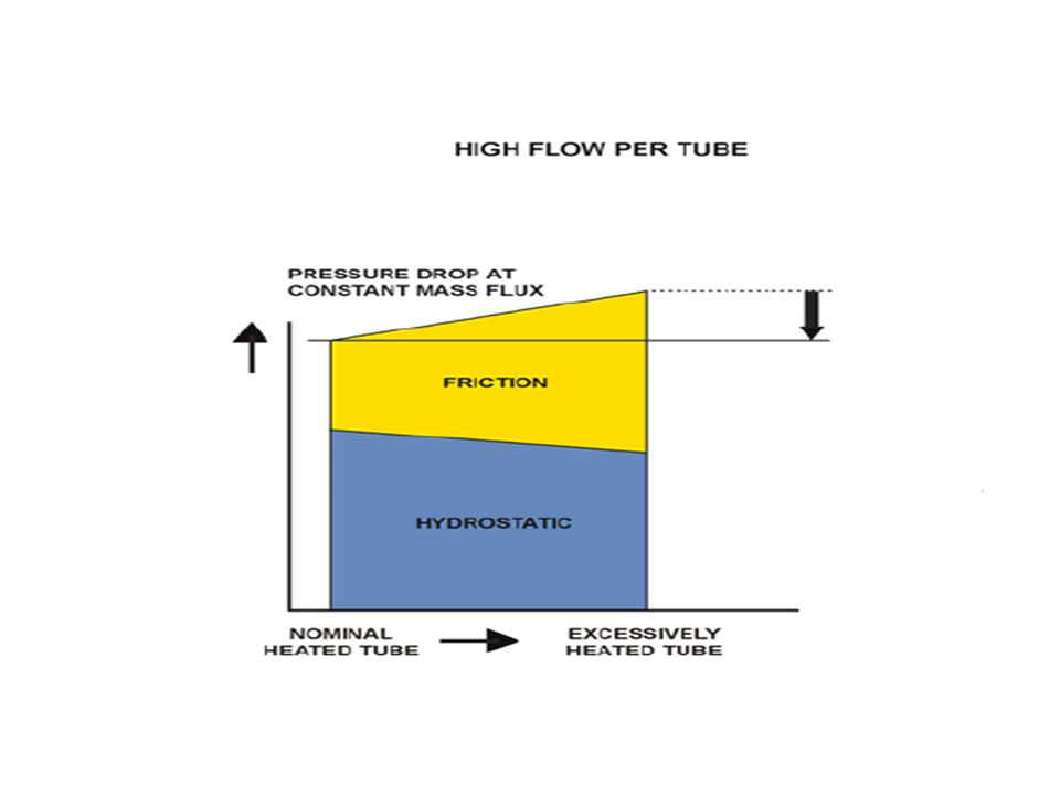
A once-through forced circulation furnace with high mass flow: If any tube receives more heat than the average, then it will accept receives less flow. This can result in further increasing temperatures, potentially leading to failures. Thus the mass flow per tube must start very high to ensure adequate remaining flow after the heat upsets. Designs with medium mass flow: These were attempted in once through forced circulation boilers with moderate success. These exhibit worse consequences than the high mass flow designs. When the mass flow is degraded during load reduction in a tube receiving more heat than the average, the remaining flow will have less margin to provide acceptable cooling. Medium mass flow designs can experience heat upsets and/or flow excursions that result in flows in individual tubes that are lower than the low mass flow design.

39
Destructive Mechanisms in Forced Circulation/Onec through

42
Both the multi-pass and the spiral designs use high fluid mass flows.
High fluid mass flow rates result in high pressure losses as well as a “once-through” . Means that strongly heated tubes have a reduction in fluid mass flow and a correspondingly high increase in fluid and therefore metal temperature which can result in excessive tube-to-tube temperature differentials. This type of behavior is sometimes referred to as a "negative flow“ characteristic. In the Vertical design, the furnace enclosure is formed from a single, upflow pass of vertical tubes.

43
The tube size and spacing is selected to provide a low fluid mass flow rate of approximately 1000 kg/m2-s or less. With low mass flow rates, the frictional pressure loss is low compared to the gravitational head, and as a result, a tube that is heated strongly, i.e., absorbs more heat, draws more flow. With an increase in flow to the strongly heated tube, the temperature rise at the outlet of the tube is reduced which limits the differential temperature between adjacent tubes. This is known as the "natural circulation” or "positive flow" characteristic. Minimize peak tube metal temperatures. To minimize peak tube metal temperatures, multiple pass and spiral types designs use high fluid mass flow rates to achieve good tube cooling. This results in the "once-through” characteristic noted above.

44
The State of the Art : The Market
In the past both the multi-pass and the spiral designs were using high fluid mass flows. High fluid mass flow rates result in high pressure losses as well as a “once-through”. Means that strongly heated tubes have a reduction in fluid mass flow and a correspondingly high increase in fluid and therefore metal temperature which can result in excessive tube-to-tube temperature differentials. This type of behavior is sometimes referred to as a "negative flow“ characteristic. In the Vertical design, the furnace enclosure is formed from a single, upflow pass of vertical tubes.

45
The tube size and spacing is selected to provide a low fluid mass flow rate of approximately 1000 kg/m2-s or less. At low mass flow rates, the frictional pressure loss is low compared to the gravitational head. A tube that is heated strongly, i.e., absorbs more heat, draws more flow. With an increase in flow to the strongly heated tube, the temperature rise at the outlet of the tube is reduced. This limits the differential temperature between adjacent tubes. This is known as the "natural circulation” or "positive flow" characteristic. Minimize peak tube metal temperatures.

46
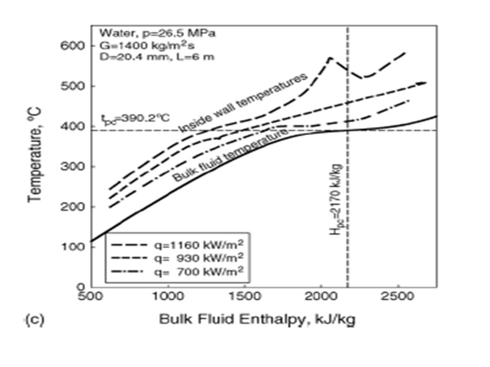
Heat Transfer Deterioration
At optimal mass flow & heat flux the wall temperature behaves smoothly and increases with increasing bulk temperature. The difference between wall temperature and fluid bulk temperature remains small. At high heat flux the wall temperature increases sharply and decreases again. This large increase in temperature is referred to Heat Transfer Deterioration. There is no unique definition for onset of Heat Transfer Deterioration. This puts a great challenge to boiler water wall design.

48
Supercritical Benson Steam Generator
Supercritical units use a once-through design, also referred to as the Benson cycle. In a once-through boiler the fluid passes through the unit one time, and there is no recirculation as takes place in the water walls of a typical drum-type boiler. Since there is no thick-walled steam drum, the startup time and ramp rates for a once-through unit can be significantly reduced from that required for a drum-type unit.

49
Circulation Vs Once Through

51
Special Features of Supercritical Steam Generators
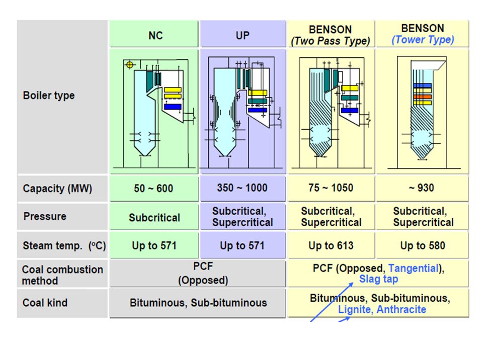
Wall thicknesses of the tubes and headers need to be designed to match the planned pressure level. At the same time, the drum of the drum-type boiler which is very heavy and located on the top of the boiler can be eliminated. Once-through boilers can be operated at variable steam pressure. Once-through boilers have been designed in both two-pass and tower type design. Large once-through boilers have been built with a spiral shaped arrangement of the tubes in the evaporator zone. The latest designs of once-through boilers use a vertical tube arrangement.

52
Examples of Once-through Boilers

53
BENSON BOILER ARRANGEMENTS
Benson boilers are designed and constructed in two basic arrangements, the two-pass or tower type. Both perform equally well. The selected arrangement is generally driven by customer preference and site-specific factors. Some particular advantages of the two-pass design are: Small plant profile (height); Lower cost construction; More optimized heating surface size because of decoupling back-pass from furnace section; Smaller stack height requirement, depending on regulations. The tower arrangement also has certain advantages. They are: Small plant footprint, especially if fitted with SCR; Even flow distribution of flue gas and particulates; Lower flue gas velocity and erosion potential; Direct load transmission to the boiler roof and free expansion; No temperature differences between adjacent wall systems; Ease of extreme cycling operation.
; Lower cost construction; More optimized heating surface size because of decoupling back-pass from furnace section; Smaller stack height requirement, depending on regulations. The tower arrangement also has certain advantages. They are: Small plant footprint, especially if fitted with SCR; Even flow distribution of flue gas and particulates; Lower flue gas velocity and erosion potential; Direct load transmission to the boiler roof and free expansion; No temperature differences between adjacent wall systems; Ease of extreme cycling operation.")
54
1000MW BABCOCK-HITACH

55
Main Specifications

56
Once Through SG Furnace Arrangements

58
Furnace Arrangements In a rectangular furnace, the heat flux imposed upon the furnace walls is not evenly distributed as shown below. To accommodate the differences in heat flux around the periphery of the furnace and the upsets inherent in the combustion process, sufficient fluid flow must be provided to each tube to maintain tube temperatures within acceptable limits over the load range.

60
Vertical Tube Furnace To provide sufficient flow per tube, constant pressure furnaces employ vertically oriented tubes. Tubes are appropriately sized and arranged in multiple passes in the lower furnace where the burners are located and the heat input is high. By passing the flow twice through the lower furnace periphery (two passes), the mass flow per tube can be kept high enough to ensure sufficient cooling. In addition, the fluid is mixed between passes to reduce the upset fluid temperature.
, the mass flow per tube can be kept high enough to ensure sufficient cooling. In addition, the fluid is mixed between passes to reduce the upset fluid temperature.")
61
Spiral Tube Furnace The spiral design, on the other hand, utilizes fewer tubes to obtain the desired flow per tube by wrapping them around the furnace to create the enclosure. This also has the benefit of passing all tubes through all heat zones to maintain a nearly even fluid temperature at the outlet of the lower portion of the furnace. Because the tubes are “wrapped” around the furnace to form the enclosure, fabrication and erection are considerably more complicated and costly.

62
Riffled Tubes The advanced Vertical technology is characterized by low fluid mass flow rates. Normally, low fluid mass flow rates do not provide adequate tube cooling when used with smooth tubing. Unique to the Vertical technology is the use of optimized rifled tubes in high heat flux areas to eliminate this concern. Rifled in the lower furnace, smooth-bore in the upper furnace. The greatest concern for tube overheating occurs when the evaporator operating pressure approaches the critical pressure. In the range 210 to 220 bar pressure range the tube wall temperature required to cause film boiling (departure from nucleate boiling – DNB) quickly approaches the fluid saturation temperature.
 quickly approaches the fluid saturation temperature.")
64
DNB will occur in this region and a high fluid film heat transfer coefficient is required to suppress the increase in tube wall temperature. Standard rifled tubing will provide an improvement in heat transfer.

65
High main steam temperature even at part loads
Main steam temperatures in the once through boiler are independent of load. This results in a higher process efficiency for the power plant over a wide load range. The fuel/feed water flow ratio is controlled in the once through boiler such that the desired steam temperature is always established at the main steam outlet. This is made possible by the variable evaporation endpoint. The evaporation and superheating surfaces automatically adjust to operating conditions. In dynamic processes, desuperheaters support maintenance of constant main steam temperature.

66
Minimum output in once-through operation at high main steam temperatures is 35 to 40% for furnace walls with smooth tubes and is as low as 20% if rifled tubes are used.

68
Fuel Flexibility Compare the behavior of a natural circulation boiler and a Benson boiler with a hypothetical ± 10% deviation of furnace heat absorption due to varying combustion and slagging characteristics. In the natural circulation boiler, the result of reduced furnace heat absorption is an increased furnace exit gas temperature and a higher steam attemperation rate. In the case of enhanced furnace heat absorption, the attemperation rate is gradual reduced to zero and the superheater outlet temperature drops. In contrast, the Benson boiler balances differences in heat absorption via the variable evaporation end-point. The allocation of the evaporative and superheat duties to the various surfaces may vary according to differential heat absorption of the furnace as well as with changing load. By controlling the firing rate according to final steam temperature, rather than to drum pressure, the Benson boiler achieves the desired steam temperature, at nearly constant attemperation rate, largely independent of shifts in heat absorption of the heating surfaces.

69
Fuel Flexibility

70
Furnace Design Vs Ash Content

71
Issues with High Ash Coals
Severe slagging and/or fouling troubles that had occurred in early installed coal fired utility boilers are one of the main reasons that led to their low availability. Furnace dimensions are determined based on the properties of coals to be burned. Some coals are known to produce ash with specific characteristics, which is optically reflective and can significantly hinder the heat absorption. Therefore an adequate furnace plan area and height must be provided to minimize the slagging of furnace walls and platen superheater sections.

72
The furnace using high ash coal need to be designed such that the exit gas temperature entering the convection pass tube coils would be sufficiently lower than the ash fusion temperatures of the fuel. For furnace cleaning, wall blowers will be provided in a suitable arrangement. In some cases as deemed necessary, high-pressure water-cleaning devices can be installed. As for fouling, the traverse pitches of the tubes are to be fixed based on the ash content/properties. An appropriate number and arrangement of steam soot blowers shall be provided for surface cleaning.

73
Countermeasures for Circumferential Cracking
There have been cases of waterwall tube failures caused by circumferential cracking in older coal-fired boilers. It is believed that this cracking is caused by the combination of a number of phenomena, the metal temperature rise due to inner scale deposits, the thermal fatigue shocks caused by sudden waterwall soot-blowing, and the tube wastage or deep penetration caused by sulfidation. Metal temperature rise due to inner scale deposits can be prevented by the application of an OWT water chemistry regime.

74
7-year OWT experience in 1,000MW supercritical coal firing boiler in Japan

75
In high sulfur coal firing boilers, the tube wastage from sulfidation is to be controlled by applying protective coatings in appropriate areas of the furnace, as well as by the selection of optimum burner stoichiometry. The sudden metal temperature change due to periodic de-slagging can be minimized by optimized operation of wall blowers or high-pressure water cleaning systems.

76
Closing Remarks on Super Critical Steam Generators
Critical to the design of a supercritical once-through boiler is the design of the furnace steam/water evaporator circuitry, the associated start-up system. How they are integrated with the firing and heat recovery area (HRA) systems. To provide safe and reliable operation of a once-through supercritical boiler requires minimizing peak tube metal temperatures and limiting the temperature differential between adjacent enclosure tubes. The Vertical boiler addresses these issues in the following unique and effective ways:
 systems. To provide safe and reliable operation of a once-through supercritical. boiler requires minimizing peak tube metal temperatures and limiting the temperature differential between adjacent enclosure tubes. The Vertical boiler addresses these issues in the following unique and effective ways:")
77
Limit tube-to-tube temperature differentials.
In a once-through boiler which operates at supercritical pressure, there is no distinction between liquid and vapor phases, and there is a continual increase in fluid temperature. Radial unbalances in heat absorption occur due to, tube geometric position, burner heat release pattern, Furnace cleanliness, variations in flow rate, caused by hydraulic resistance differences from tube-to-tube, All the lead to variations in tube temperatures occur. High differential temperatures induce high thermal stresses, which, if not limited, can result in tube failure.

78
Historically, this issue has been addressed in two different ways:
In units with multiple passes in the furnace evaporator, the differential temperature is limited by the fact that each pass picks up a fraction of the total evaporator duty. This limits the magnitude of the unbalance and intermediate mixing occurs before the fluid is distributed to the next downstream pass. However, with multiple passes, the furnace must operate at supercritical pressure throughout its load range to avoid the difficulties of uniformly distributing a steam-water mixture to the down stream passes.

79
In units with a spiral tube configuration, the unbalance issue is addressed by having each inclined tube pass through the varying heat absorption zones so that each tube absorbs approximately the same amount of heat. With a single up-flow pass, the spiral design can operate with variable pressure steam, which minimizes part load auxiliary power requirements and allows matching of steam and turbine metal temperature for extended steam turbine life. However, the spiral tube evaporator configuration requires a special support system for the inclined tubes, which are not self-supporting.

80
Present Status of Technology
Many of the "supercritical-related" problems with the early supercritical units have been resolved with new designs. New units are also designed to operate with sliding pressure, which improves load change characteristics. Once-through design is now available with faster responding controls and adaptive tuning over the entire load range.

81
Sliding Pressure Operation
P M V Subbarao Professor Mechanical Engineering Department I I T Delhi High Efficiency at Part Loads………

82
Sliding pressure operation
Variable pressure operation (sliding pressure operation) is desired in many modern power plants because it provides more efficient part load operation. The loss due to constant pressure operation at low load is always a concern for the utility. The vertical tube supercritical boiler can provide variable turbine pressure operation to gain the thermodynamic advantage of variable pressure. Since the boiler furnace must be operated in the supercritical region, this is accomplished by a pressure-reducing valve located between superheater stages. Thus the turbine efficiency advantages are obtained but without the savings in boiler feed pump power associated with true variable pressure operation.
 is desired in many modern power plants because it provides more efficient part load operation. The loss due to constant pressure operation at low load is always a concern for the utility. The vertical tube supercritical boiler can provide variable turbine pressure operation to gain the thermodynamic advantage of variable pressure. Since the boiler furnace must be operated in the supercritical region, this is accomplished by a pressure-reducing valve located between superheater stages. Thus the turbine efficiency advantages are obtained but without the savings in boiler feed pump power associated with true variable pressure operation.")
83
The spiral tube furnace design can be operated in the subcritical region thus also providing the pump power savings. The advanced SC boiler with vertical internally ribbed tube furnace design may also be operated in the subcritical region. This provides the same pump power savings in variable pressure operation plus the advantage of a lower full load pressure loss for additional power savings. Temperature changes occur in the boiler and in the turbine during load changes. These can cause thermal stresses in thick walled components. These are especially high in the turbine during constant-pressure operation. They therefore limit the maximum load transient for the unit.

84
By contrast, in sliding pressure operation, the temperature changes are in the evaporator section.
However, the resulting thermal stresses are not limiting in the Once through boiler due to its thermo elastic design. In fixed pressure operation , temperature change in the turbine when load changes, while in sliding-pressure operation ,they change in the boiler

86
The enthalpy increase in the boiler for preheating, evaporation and superheating changes with pressure. However, pressure is proportional to output in sliding pressure operation. In a uniformly heated tube, the transitions from preheat to evaporation and from evaporation to superheat shift automatically with load such that the main steam temperature always remains constant.

87
While sliding pressure is beneficial for the turbine, it can cause difficulties for the boiler.
The following adverse effects can occur: As the pressure falls, the boiling temperature (boiling point) changes. The boiler is divided into zones in which the fluid is expected to be entirely water, mixed steam / water or dry steam. A change in the boiling point can change the conditions in each zone. The heat transfer coefficient in each zone depends upon the pressure. As the pressure falls, the heat transfer coefficient reduces. This means that the steam may not reach the correct temperature. Also, if heat is not carried away by the steam, the boiler tubes will run hotter and may suffer damage.
 changes. The boiler is divided into zones in which the fluid is expected to be entirely water, mixed steam / water or dry steam. A change in the boiling point can change the conditions in each zone. The heat transfer coefficient in each zone depends upon the pressure. As the pressure falls, the heat transfer coefficient reduces. This means that the steam may not reach the correct temperature. Also, if heat is not carried away by the steam, the boiler tubes will run hotter and may suffer damage.")
88
The heat transfer coefficient also depends upon the velocity of the steam in the boiler tubes.
Any change in pressure causes a change in steam density and so alters the steam velocities and heat transfer rate in each zone. Pressure and temperature cause the boiler tubes to expand. If conditions change, the tubes will move. The tube supports must be capable of accommodating this movement. The expansion movements must not lead to adverse stresses. The ability to use sliding pressure operation is determined by the boiler

89
Boilers can be designed to accommodate sliding pressure.
When it is used, coal fired boilers in the 500 to 1000 MW class normally restrict sliding pressure to a limited load range, typically 70% to 100% load, to minimize the design challenge. Below this range, the boiler is operated at a fixed pressure. This achieves an acceptable result because large units are normally operated at high load for economic reasons. In contrast, when sliding pressure is used in combined cycle plant, the steam pressure is varied over a wider load range, typically 50% to 100% load or more.

90
As stated, in coal-fired plant, sliding pressure is normally restricted to a limited load range to reduce design difficulties. In this range, the boiler pressure is held at a value 5% to 10% above the turbine internal pressure. Consequently, the governor valves throttle slightly. The offset is provided so that the unit can respond quickly to a sudden increase in load demand simply by pulling the valves wide open. This produces a faster load response than raising the boiler firing rate alone.The step in load which can be achieved equals the specified margin ie 5% to 10%.

91
The throttling margin is agreed during the tendering phase and then fixed.
A margin of 5% to 10% is usually satisfactory because most customers rely upon gas turbines, hydroelectric or pumped storage units to meet large peak loads. The throttling margin means that the full potential gain of sliding pressure is not achieved. Nevertheless, most of the throttling losses which would otherwise occur are recovered.

93
Sliding Pressure 24.1 Mpa 6.9 Mpa

94
During such operation, the pressure is determined by the turbine system and the boiler is operated by fully opening the turbine inlet valve. At constant-pressure operation, on the contrary, the turbine inlet pressure is controlled by throttling the turbine inlet valve, which results simultaneously in the control of the flow rate. This induces reduction in efficiency owing to the irreversibility of the throttling. On the other hand the efficiency drop at partial load is small because of the nonexistence of throttle loss. At loads of %, the system pressures are in the supercritical region. In contrast, at 77-25% loads, the system pressures are in the sub critical region and boiling occurs in the water-wall tubes, while the state of the fluid at the outlet of the water wall is superheated steam.

95
There are no operational limitations due to once-through boilers compared to drum type boilers.
In fact once-through boilers are better suited to frequent load variations than drum type boilers, since the drum is a component with a high wall thickness, requiring controlled heating. A principle advantage of once through boiler is that it does not require circulating pumps or drums. Energy required for circulation is provide by the feed pump.

Similar presentations


![An Introduction To Marine Steam Propulsion Plant [Source: US Navy]](/2/754532/big_thumb.jpg "An Introduction To Marine Steam Propulsion Plant [Source: US Navy]>")


