Download presentation
Presentation is loading. Please wait.

1
Further Development of Post- Tensioned Prestressed Concrete Pavement in Texas Short Course Material Stage I – Design of a PCP TxDOT Research Project 0-4035 Developed by Center for Transportation Research The University of Texas at Austin

2
This CD was developed in compliance with TxDOT Research Project 0-4035 Task 10.5. The material contained here intends to serve as a guide for pavement engineers to learn about the procedure followed in this project to design a post-tensioned prestressed concrete pavement (PCP). This material only presents the design procedure; however, complementary information about Project 0-4035 might be found in the technical reports prepared for the project. This reports can be accessed through the Internet at the Center for Transportation Researchs Library Website. http://www.utexas.edu/research/ctr/ Introduction
. This material only presents the design procedure; however, complementary information about Project might be found in the technical reports prepared for the project. This reports can be accessed through the Internet at the Center for Transportation Researchs Library Website. Introduction.")
3
For any questions or comments related to this material or project, please contact the research agency: Center for Transportation Research Atn. Dr. Cesar I Medina-Chavez 3208 Red River Suite 104 Austin, TX 78712 Phone (512) 232-3100 E-mail address: cimedina@mail.utexas.edu Contact
 address: Contact.")
4
Acronyms found in the literature that refer to Prestressed Concrete Pavement are: PSCP, PTCP, PCP Background In prestressed pavement the concrete slab is preloaded (before traffic loads) Post-tensioned: it means preload is applied after concrete has gained sufficient strength
 Post-tensioned: it means preload is applied after concrete has gained sufficient strength")
5
Why use Prestressing Techniques? Concrete is essentially a compression material Its strength in tension is low Prestressing naturally involves compressive loading prior to application of service loads Tensile stresses are reduced or eliminated Background

6
Improve the design and construction techniques for a cost effective state- of-the-art pavement structure and apply them in a new design Project Objective

7
Reference Material Literature Review (Chapter 2) PCP use in Texas (Chapter 3) Evaluation of PCP in Texas (Chapter 4) Design of PCP (Chapter 5) Materials and Construction Specifications (Chapter 6) Discussion of Developments (Chapter 9) Monitoring Plan for New PCP (Chapter 7) PCP and CRCP Comparison (Chapter 8) Conclusions and Recommendations (Chapter 10) I. Evaluation of Previous Work II. New Developments Click here to open the report (5.5 Mb PDF file) Report 0-4035-1
 Report")
8
Prestressing principles date from 1888 Eugene Freyssinet started applications in 1910 PCP application goes back to the 1940s in England and France Brief Prestressing History

9
APPLICATION OVERSEAS First application in England in 1943 Then in Paris, France at Orly Airport Other projects in Austria, Belgium, Germany, The Netherlands, Switzerland, etc. Japan

10
EARLY DOMESTIC EXPERIENCE In 1953 in Maryland (Airfield - 7 in. PCP Patuxent River Naval Air Station) In 1959 in San Antonio, TX (Taxiway at Biggs Air Force Base) Other experimental projects: Pittsburgh, PA (1971) Dulles Intl. Airport, VA (1971)
 In 1959 in San Antonio, TX (Taxiway at Biggs Air Force Base) Other experimental projects: Pittsburgh, PA (1971) Dulles Intl. Airport, VA (1971).")
11
EARLY DOMESTIC EXPERIENCE After a feasibility study the FHWA decided to develop PCP projects in 3 States Characteristics of PCPs in PA, MS, AZ – Only longitudinal post-tension was applied – Post-tensioning applied in gap slabs – 24 ft-wide placements – 6 in.-thick slabs

12
Gap Slab Active Joint 24 ft Gap Slab

13
Used in projects in PA, MS, and AZ Disadvantages of Gap Slabs : Require 2 joints per slab Additional construction operation Delayed opening to traffic Greater chance of failure Higher costs PCPSlab PCP Slab 400-600 GapSlab Gap Slab 3-8 Gap Slab

14
IMPROVED DOMESTIC EXPERIENCES IL – OHare Intl. Airport (1980) TX – Highway IH-35 (1985) PA - Highway US220 (1988) IL – Greater Rockford Airport (1993)
 TX – Highway IH-35 (1985) PA - Highway US220 (1988) IL – Greater Rockford Airport (1993).")
15
During the early 1980s CTR introduced innovations based upon the successes and failures of projects in PA, MS, an AZ – Used Central Stressing Pockets instead of Gap Slabs – Applied Longitudinal and Transverse Prestress A 6 in-thick PCP overlay was constructed in 1985 near West, Texas in McLennan County After almost 20 years of service the PCP is in excellent condition under heavy truck traffic Texas Case

16
Concept Developed by CTR researchers Requires 1 joint per slab Advantages are: No delayed opening to traffic Decreased construction time Less chance of failure Less maintenance Central Stressing Pocket

17
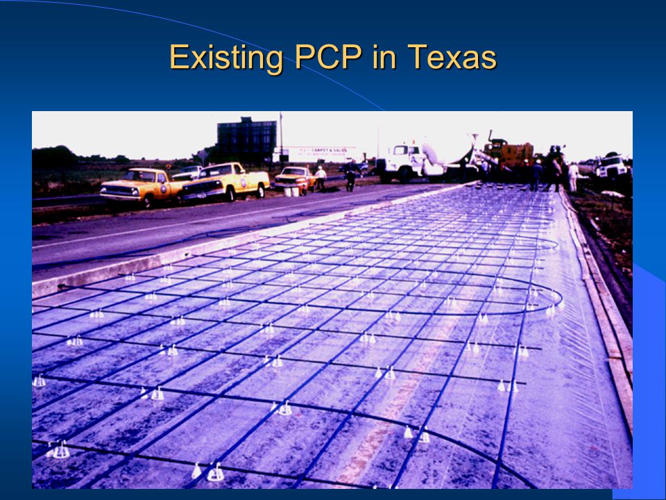
Existing PCP in Texas

19
Total of 32 Prestressed Pavement Slabs 7 – 440 ft x [ 17 ft + 21 ft ] 9 – 240 ft x [ 17 ft + 21 ft ] 7 Slabs @ 440 ft = 3080 ft 9 Slabs @ 240 ft = 2160 ft Total = 5240 ft IH - 35 N Exit 351 Wiggins Road FM 1858 Frontage Waco 15 miles Existing PCP in Texas on IH-35
![Total of 32 Prestressed Pavement Slabs 7 – 440 ft x [ 17 ft + 21 ft ] 9 – 240 ft x [ 17 ft + 21 ft ] ft = 3080 ft ft = 2160 ft Total = 5240 ft IH - 35 N Exit 351 Wiggins Road FM 1858 Frontage Waco 15 miles Existing PCP in Texas on IH-35](http://images.slideplayer.com/5/1586837/slides/slide_19.jpg "Total of 32 Prestressed Pavement Slabs 7 – 440 ft x [ 17 ft + 21 ft ] 9 – 240 ft x [ 17 ft + 21 ft ] ft = 3080 ft ft = 2160 ft Total = 5240 ft IH - 35 N Exit 351 Wiggins Road FM 1858 Frontage Waco 15 miles Existing PCP in Texas on IH-35")
20
Cross section construction history, according to TxDOTs files: 1952 JCP Granular base Natural soil Lime stabilized sub-base 12" 5" 6" 1975 ACP 4" 1985 and current PCP6" Existing PCP in Texas

21
Outline a procedure that can be used as a guide for designing any PCP Use past experiences and apply them in the new design Foreign, PA, MS, AR, IL TX – Old PCP and Precast Slab Concrete Pavement in Georgetown, TX Apply process to design a PCP on IH-35 near Hillsboro, TX in Hill County Design of New PCP Methodology

22
Literature review – Documentation of previous work (domestic and abroad) Selection of construction site and evaluation of existing pavement conditions Site visits Development of work plan Design of New PCP Approach
 Selection of construction site and evaluation of existing pavement conditions Site visits Development of work plan Design of New PCP Approach")
23
Factors affecting design – Traffic Loads – Temperature effects – Moisture effects – Slab friction resistance – Prestress losses – Transverse prestress – Joint movement Design of New PCP Design Considerations

24
Design variables – Foundation strength and embankment properties – Pavement thickness – Magnitude of prestress – Slab length – Slab width Design of New PCP Design Considerations

25
Design Steps for New PCP in Hillsboro, Texas – Embankment issues – Condition survey – Deflection measurement – Existing pavement back calculation – Traffic data analysis – Thickness design – Slab length Design of New PCP Implementation of Design Considerations

26
Location Between Mileposts 365 and 368 both directions Design of New PCP

27
Condition Survey- Evaluate existing pavement condition Design of New PCP

28
Condition Survey- Evaluate existing pavement condition Design of New PCP

29
–Pavement in Fair Condition –Transverse Cracks –Longitudinal Cracks –Rutting –Patches –Alligator Cracking Condition Survey Summary Design of New PCP

30
Condition Survey Quantitative Analysis Use Pavement Distress Index (PDI) Mathematical combination of distresses Assign weight factor (WF) Assign severity factor (SF) 14 different distresses Severity: Low-Moderate-High To calculate PDI, each distress is assigned WF and SF Design of New PCP
 Mathematical combination of distresses Assign weight factor (WF) Assign severity factor (SF) 14 different distresses Severity: Low-Moderate-High To calculate PDI, each distress is assigned WF and SF Design of New PCP")
31
Where: D i = deducted points of the i th type distress, S ij = weight of the j th severity class of the ith type of distress, E ij = extent of the j th severity class of the ith type distress, n = number of distress types, m = number of severity classes Pavement Distress Index (PDI) PDI Chia-Pei-Chou TRB Record 1592 Design of New PCP
 PDI Chia-Pei-Chou TRB Record 1592 Design of New PCP")
32
PDI Chia-Pei-Chou TRB Record 1592 Distress weight factor (49-100) Severity factor (based on distress 0.24-1.00) Extent (percent of area/occurrence frequency) Design of New PCP Pavement Distress Index (PDI)
 Severity factor (based on distress ) Extent (percent of area/occurrence frequency) Design of New PCP Pavement Distress Index (PDI)")
33
DirectionNo. of subsectionsGroup Number Scores * NB211,277 - 97 SB22 3 1,2,3,4 63 91 - 86 - 63 - 99 Maximum Score: 100.00 *PDI Chia-Pei-Chou TRB Record 1592/CTR Report 87.0 84.7 Summary Pavement Distress Index (PDI) Design of New PCP
 Design of New PCP.")
34
Structural Evaluation of Existing Pavement Design of New PCP

35
Deflection Data Collection Using RDD Design of New PCP

36
Deflection Data Collection Using FWD Design of New PCP

37
Back Calculation of Pavement Structure Design of New PCP

38
Back calculation of layer properties 10 109134 194268 43513075 681760 Natural Soil SG SB CRCP ACP Computed Modulus (ksi) SB Computed Modulus (ksi) NB Layer No. Design of New PCP

39
The existing asphalt pavement was visually inspected and a pavement distress index (PDI) was calculated for each highway direction. Next, pavement deflections were measured using the rolling dynamic deflectometer (RDD) and the falling weight deflectometer (FWD). Those deflections were used to estimate or backcalculate the elastic properties of the pavement. The next step involved the estimation of the projected traffic for the design lane. In this case, the calculation of the projected equivalent single axle loads (ESALs) was performed by TxDOT and the information was provided to the researchers to conduct a pavement fatigue analysis.
 and the falling weight deflectometer (FWD). Those deflections were used to estimate or backcalculate the elastic properties of the pavement. The next step involved the estimation of the projected traffic for the design lane. In this case, the calculation of the projected equivalent single axle loads (ESALs) was performed by TxDOT and the information was provided to the researchers to conduct a pavement fatigue analysis..")
40
Layer elastic properties were backcalculated using deflection information ESALs information was provided by TxDOT ESAL projections were done for 30 years Design of New PCP Design Process Recap

41
Design of equivalent pavement 30 year life 114 million ESAL applications Concrete flexural strength: 700 psi Concrete modulus of elasticity: 4,000 ksi Two different conditions were analyzed Overlay of existing pavement Pavement on median Design of New PCP Elastic Design for Fatigue Loading

42
Design of New PCP Elastic Design for Fatigue Loading The design was performed for two different pavement cross sections, for an overlay of the existing asphalt pavement and a new pavement to be constructed on the existing median. In both cases, an equivalent continuously reinforced concrete pavement (CRCP) was designed using AASHTOs design procedure. The thicknesses obtained were as follows: Equivalent CRCP for overlay: 14 in. Equivalent CRCP for pavement on median: 15 in.
 was designed using AASHTOs design procedure. The thicknesses obtained were as follows: Equivalent CRCP for overlay: 14 in. Equivalent CRCP for pavement on median: 15 in..")
43
Equivalent CRCP for Overlay

44
Equivalent CRCP for Pavement on Median

45
Design of New PCP Elastic Design for Fatigue Loading The next step was to calculate the minimum required prestress for various PCP thicknesses. The analysis included estimation of the prestress for various thicknesses from 6 in. to 15 in. The required prestress increased as the thickness decreased. This means they are inversely proportional. For instance, a 6 in.-thick PCP for the overlay design requires 49.1 psi of prestress to compensate for thickness. Likewise, a 14.0 in.-thick PCP will not require any additional prestress. That would be the equivalent CRCP entire thickness.

46
Thickness vs. Required Prestress 0 20 40 60 80 100 120 PCP Thickness (in) Required Prestress (psi) Existing Pavement Overlay 49.136.626.817.314.29.55.41.70 New Pavement on Median 107.682.662.646.83423.214.16.50 67891011121314 14 / 15
 Required Prestress (psi) Existing Pavement Overlay New Pavement on Median / 15.")
47
The next step in the design is to consider the effect of the combination of environmental stresses and wheel load stresses. The following conditions should be met: Critical stresses at PCP must not cause fatigue failure of the prestressed slab Combination of wheel loads, slab DT, and moisture stresses should not exceed flexural strength of concrete Design of New PCP Elastic Design for Environmental Stresses and Wheel Loads

48
f = allowable flexural stress in the concrete s p = effective prestress s t = stress caused by applied wheel load s c = curling stress due to slab temperature differentials s F = friction loss between slab and supporting layer Design of New PCP f + s p s t + s c + s F Elastic Design for Environmental Stresses and Wheel Loads The basic equation to be used is:

49
Design of New PCP Using the basic equation previously shown, the PCP is designed as follows: Prestress at end of slab is computed Prestress losses are estimated and discounted Strand spacing is calculated Iterative process Vary length and thickness Other properties considered are – Aggregate type, Poissons ratio, flexural strength, modulus of elasticity – Climatic variables

50
Design of New PCP It is recommended to design PCP using a spreadsheet and vary slab length and thickness. Final design characteristics are based on engineering judgment. Concrete and Pavement Properties

51
Design of PCP Using Spreadsheets Prestressing Tendon Properties Climatic Factors Design of New PCP

52
Summary of PCP Characteristics Design FeatureRecommendation Design life30 years Projected traffic for design life114 million ESALs Concrete design flexural strength700 psi Concrete modulus of elasticity4,000 ksi Thickness of PCP slab9 in. Length of PCP slab300 ft

53
– A similar expansion joint as in previous PCP in McLennan County will be used – Joint has proven to be durable and adequate – A better neoprene seal will be used Transverse Expansion Joint Design Practical Considerations

54
Transverse Expansion Joint

55
The new design is based on improvements of previous experiences (PCP near West, TX) New PCP is an interesting project that will promote research and innovative construction practices Two designs have been conducted – PCP overlay on existing asphalt pavement – PCP on median Joint spacing will be limited to 300 ft Thickness will be 9 in. Discussion of Developments

56
Construction of PCP allows a more efficient use of construction materials Less concrete Application of prestressing forces makes use of the compressive strength of concrete and reduces tensile stresses A well constructed PCP highly reduces maintenance tasks costs Concluding Remarks

57
Dr. B. Frank McCullough Project Supervisor, CTR Dr. Moon C. Won Project Director, TxDOT Acknowledgements

Similar presentations