Download presentation
Presentation is loading. Please wait.

1
Agenda – Day 1 8:00 am – 8:15 am Introductions and House Keeping
8:15 am – 8:45 am Session 1: Load Rating Basics 8:45 am – 9:30 am Session 2: Basic Load Rating Calculations 9:30 am – 9:45 am Break 9:45 am – 11:45 am Session 3: Example – Load Rating Concrete Slab Bridge 11:45 am – 12:00 pm Questions 12:00 pm – 1:00 pm Lunch 1:00 pm – 2:30 pm Session 4: Example – Load Rating Steel Beam Bridges 2:30 pm – 2:45 pm Break 2:45 pm – 3:45 pm Session 4: Example – Load Rating Steel Beam Bridges (Con’t) 3:45 pm – 4:00 pm Questions Load Rating Seminar
 3:45 pm – 4:00 pm Questions. Load Rating Seminar.")
2
Session 2: Basic Load Rating Calculations
Capacity Calculations (C) Dead Load Calculations (DL) Live Load Calculations (LL + I) Rating Factor (RF) LFR: RF = Capacity – A1 (DL) A2 (LL + I)
 Dead Load Calculations (DL) Live Load Calculations (LL + I) Rating Factor (RF) LFR: RF = Capacity – A1 (DL) A2 (LL + I)")
3
Capacity Calculations
Capacity (C) depends on material, shape, & Condition Generally for normal bridges, bending controls the load rating of the bridge. Section loss at beam ends may make shear or bearing control the bridge capacity Examples will show how to calculate C
 depends on material, shape, & Condition. Generally for normal bridges, bending controls the load rating of the bridge. Section loss at beam ends may make shear or bearing control the bridge capacity. Examples will show how to calculate C.")
4
Capacity Calculations
What to do when you don’t know material properties ODOT BDM Figures 904 and 905 give material properties based on year built. Be careful during transition years. See Appendix A

5
Capacity Calculations
What to do when you don’t know Section properties Steel Members: AISC Manual of Steel Construction give section properties See Appendix B for section properties for shapes rolled between 1873 and 1952 (Thank you B&N) Measure the beams in the field – beam depth, flange width, web thickness, flange thickness (be careful with I and S shapes – bottom flanges are sloped)
 Measure the beams in the field – beam depth, flange width, web thickness, flange thickness (be careful with I and S shapes – bottom flanges are sloped)")
6
Capacity Calculations
What to do when you don’t know Section properties Concrete Members: Need to know reinforcing steel in member. Reinforcing steel can come from bridge plans, design data sheet, or standard drawing. If don’t know the reinforcing steel in member, then “engineering judgment” is acceptable.

7
Dead Load Calculations
Many bridges – DL can be applied as a uniform load (w k/ft) Cross frames Steel guardrail Standard references are available for unit weights for example: Concrete = 150 lb/cf Steel = 490 lb/cf Asphalt = 144 lb/cf
 Cross frames. Steel guardrail. Standard references are available for unit weights for example: Concrete = 150 lb/cf. Steel = 490 lb/cf. Asphalt = 144 lb/cf.")
8
Dead Load Calculations
Do not include Future Wearing Surface in this calculation. Only include the dead load that is currently on the bridge. Any superimposed dead load that is placed after deck is poured, may be distributed to all beams. An example would be railing. Moment (M) for uniform load: M = wL2/8 w = uniform load (k/ft.) L = length of beam (ft.)
 for uniform load: M = wL2/8. w = uniform load (k/ft.) L = length of beam (ft.)")
9
Dead Load Calculations
If Dead Load includes concentrated items calculate dead load moment via shear and moment diagrams. Diaphrams on pre-stressed box beams

10
Dead Load Calculations
RF = Capacity – A1 (DL) A2 (LL + I) Rating Type A1 = Factor for dead loads A2 = Factor for live load Inventory * Design level 1.3 2.17 Operating Ref: AASHTO Manual for Condition Evaluation of Bridges 1994 Load Rating Seminar
 A2 (LL + I) Rating Type. A1 = Factor for dead loads. A2 = Factor for live load. Inventory. * Design level Operating. Ref: AASHTO Manual for Condition Evaluation of Bridges Load Rating Seminar.")
11
Live Load Calculations
Items to discuss Shear and Moment diagrams Live load moment equations Live load distribution factors Wheel vs. Axle Impact factor

12
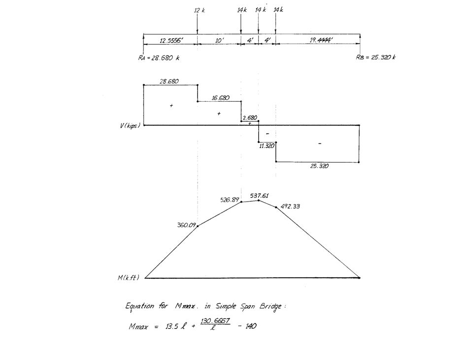
Live Load Calculations
Shear and Moment Calculations Sample set of calculations to determine maximum moment for a 4F1 truck Moment from any truck configuration can be determined this way

19
Live Load Calculations
Live Load Moment Calculations See Appendix C for live load moment equations for the Ohio load rating trucks. These are axle (full truck) live load moments
 live load moments.")
20
Live Load Calculations
Live Load Distribution Factors (LLDF) How much truck is carried by each beam or strip of slab. One Axle = 2 wheels Be careful with wheel vs. axle Be consistent with LLDF and Live load moment See Section 3.23 AASHTO Standard Specifications for Highway Bridges for wheel live load distribution factors.
 How much truck is carried by each beam or strip of slab. One Axle = 2 wheels. Be careful with wheel vs. axle. Be consistent with LLDF and Live load moment. See Section 3.23 AASHTO Standard Specifications for Highway Bridges for wheel live load distribution factors.")
21
Live Load Calculations
Live Load Distribution Factors (LLDF) - Examples Longitudinal interior steel or concrete beam w/ concrete deck and two or more lanes on bridge LLDF (wheel) = S / 5.5 S = average beam spacing Longitudinal interior steel or concrete beam w/ 4 in. thick wooden deck and two or more lanes on bridge LLDF (wheel) = S / 4.0
 - Examples. Longitudinal interior steel or concrete beam w/ concrete deck and two or more lanes on bridge. LLDF (wheel) = S / 5.5. S = average beam spacing. Longitudinal interior steel or concrete beam w/ 4 in. thick wooden deck and two or more lanes on bridge. LLDF (wheel) = S / 4.0.")
22
Live Load Calculations
Live Load Distribution Factors (LLDF) Exterior steel or concrete beams: Place wheel load 2 ft. from face of guardrail Assume deck acts as simple span Calculate the Reaction of the wheel load
 Exterior steel or concrete beams: Place wheel load 2 ft. from face of guardrail. Assume deck acts as simple span. Calculate the Reaction of the wheel load.")
23
Live Load Distribution Factor – Exterior Beam

25
Live Load Calculations
Live Load Impact Factor (I) I = 50 L + 125 I Maximum = 30 % L = length of loaded span L = span length for simple spans
 I = 50. L I Maximum = 30 % L = length of loaded span. L = span length for simple spans.")
26
Live Load Calculations
Live Load Impact Factor (I) – Example Beam is 55 ft. long L= 55 I = 50 / ( ) I = 0.28 = 28 % < 30 % I = 28 % Multiply the Live Load Moment by 1.28
 – Example. Beam is 55 ft. long. L= 55. I = 50 / ( ) I = 0.28 = 28 % < 30 % I = 28 % Multiply the Live Load Moment by")
27
Live Load Calculations
RF = Capacity – A1 (DL) A2 (LL + I) Rating Type A1 = Factor for dead loads A2 = Factor for live load Inventory * Design level 1.3 2.17 Operating Ref: AASHTO Manual for Condition Evaluation of Bridges 1994 Load Rating Seminar
 A2 (LL + I) Rating Type. A1 = Factor for dead loads. A2 = Factor for live load. Inventory. * Design level Operating. Ref: AASHTO Manual for Condition Evaluation of Bridges Load Rating Seminar.")
28
Rating Factor Calculations
Converting Rating Factor (RF) to: Percent Legal Load (Legal Load Vehicles) RF X 100 = % Legal Load Tons (Legal Load Vehicles) RF X # tons of Truck used (GVW in tons) For 5C1 Truck (GVW = 40 tons) with a RF = 1.23 Load Rating Tons = 1.23 X 40 = 49 tons HS Rating (HS 20 truck used) RF X 20 = HS rating RF = 1.56 then 1.56 X 20 = HS 31.2
 to: Percent Legal Load (Legal Load Vehicles) RF X 100 = % Legal Load. Tons (Legal Load Vehicles) RF X # tons of Truck used (GVW in tons) For 5C1 Truck (GVW = 40 tons) with a RF = Load Rating Tons = 1.23 X 40 = 49 tons. HS Rating (HS 20 truck used) RF X 20 = HS rating. RF = 1.56 then 1.56 X 20 = HS")
29
Questions ? ? ? ?

Similar presentations


>")


