Download presentation
Presentation is loading. Please wait.

1
ODOT Structure Project Manager Seminar Concrete Decks
Basic design, everyone has experience, go quickly to give flavor then some topics of interest

2
ODOT’s Requirements Materials Design Plan details Misc. Insights
NOT MUCH TO SAY HIGHLIGHT BDM REQUIREMENTS and GO A STEP FURTHER WITH SOME TOPICS OF INTEREST

3
Selection of Concrete for Bridge Decks
The following concrete types may be specified: A. Class S Concrete B. Class HP Concrete C. Class S Concrete for New Bridge Decks with Warranty D. Class HP Concrete for New Bridge Decks with Warranty E. QC/QA Concrete Class QSC2 F. QC/QA Concrete Class QSC3 District to confirm the selection of concrete to be used. Concrete Design Allowable: Load Factor Design 4500 psi

4
Reinforcing Steel Requirements
Minimum concrete cover for reinforcing A. Top reinforcing steel …………………… ½ inches B. Bottom reinforcing steel …………………….1½ inches C. Clearance to edge of deck ….……………… 3 inches All reinforcing steel shall be epoxy coated, Grade 60 ksi Suggested Minimum Lap Splices for Deck Reinforcing Steel: #4 min. lap 2’-0” #5 min. lap 2’-6” #6 min. lap 3’-0”

5
Design Requirements In order to facilitate forming, deck slab overhang should not exceed 4'-0". 1-inch monolithic concrete. This one-inch thickness shall not be considered in the structural design of the deck slab or as part of the composite section. The design live load shall be HS25 for decks on new superstructures and HS20 for decks on existing superstructures (optional HS25 per project scope). All bridges shall be designed for a future wearing surface (FWS) of 60 psf .
. All bridges shall be designed for a future wearing surface (FWS) of 60 psf .")
6
Design Thickness For reinforced concrete decks on steel or concrete stringers the deck thickness shall be computed by the following formula: Tmin (inches) = (S + 17)(12) ÷ 36 (not less than 8½ inches) Where S is the effective span length in feet. Minimum slab thickness is based on practical considerations such as adequate clearances, construction tolerances of concrete placement, deflection (serviceability), shear and bond.
 = (S + 17)(12) ÷ 36 (not less than 8½ inches) Where S is the effective span length in feet. Minimum slab thickness is based on practical considerations such as adequate clearances, construction tolerances of concrete placement, deflection (serviceability), shear and bond.")
7
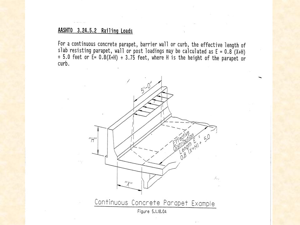
SUPPLEMENT TO AASHTO VERBAGE

8
Design Controls Flexure strength Spacing, crack control
Longitudinal distribution

10
GIVEN SPAN AND DECK THICKNESS = rebar area

13
Typical Haunch details Old reason - haunch encase top flange (compression) non-composite design Allow for beam profile differences Rehabilitation projects adjust to fit new profile Construction tolerances
 non-composite design Allow for beam profile differences Rehabilitation projects adjust to fit new profile Construction tolerances")
14
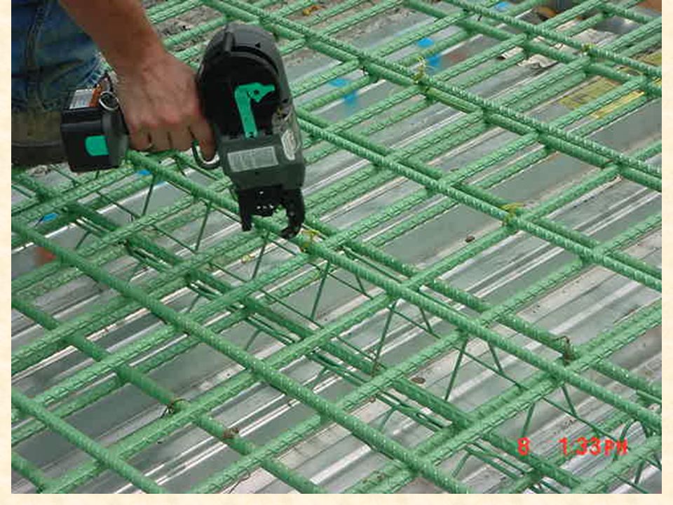
Longitudinal Reinforcing
Research has shown that secondary bars in the top mat of reinforced concrete bridge decks on stringers should be small bars at close spacing. Therefore the required secondary bar size shall be a #4. For stringer type bridges with reinforced concrete decks, the secondary bars shall be placed above the top of deck primary bars. This helps in reducing shrinkage cracking and adds additional cover over the primary bars.

15
Transverse Reinforcing
To facilitate the placement of reinforcing steel and concrete in transversely reinforced deck slabs top and bottom main reinforcement shall be equally spaced and placed to coincide in a vertical plane.

16
HOW IS ODOT DOING

17
Highlights of NCHRP 333 Concrete mix proportions should produce low-permeability, but not increase propensity for cracking Epoxy reinforcing steel with minimum practical bar size and spacing Minimum concrete cover of 2 ½ inches Develop performance based specification with warranties Adequate curing is essential Report published in 2004

18
Design Insight Deck design is known to be conservative
Conservative assumptions: Live load moment formula, same for positive and negative Point load v tire contact area Westergaard theory (1930’s) – rigid supports Wearing surface depth neglected Single vs double reinforced section Effective span length FWS weight Haunch section effects Rounding of spacing and coinciding of top and bottom reinforcing steel Higher actual material strengths Construction tolerances, deck importance, high wearing, history of good performance DECK DESIGN INSIGHTS, something to think about
 – rigid supports. Wearing surface depth neglected. Single vs double reinforced section. Effective span length. FWS weight. Haunch section effects. Rounding of spacing and coinciding of top and bottom reinforcing steel. Higher actual material strengths. Construction tolerances, deck importance, high wearing, history of good performance. DECK DESIGN INSIGHTS, something to think about.")
19
ODOT History of deck design
1940’s top cover 1 ¾ inch, bottom cover 1 inch; 180 lbs/cy, use of bent bar Asphalt concrete overlays 1950’s top cover 1 inch plus monolithic ws (CF30=1/2”;CF130=3/4”;CF400=1”), Min deck 7 ½ inches’ #6 and #5 bars 1960’s top cover 2 inches, #6 and #7 bars, 260 lbs/cy 1976 reverse main bars to today’s practice 1977 Deck protection; Primary epoxy coated steel top mat only; Secondary for ADTT greater than 5000 overlay (asphalt or concrete) 1986 epoxy coated top and bottom mats 1990’s top cover 2 ½ inches and bottom cover 1 ½ inches, min deck 8 ½ inches
, Min deck 7 ½ inches’ #6 and #5 bars. 1960’s top cover 2 inches, #6 and #7 bars, 260 lbs/cy reverse main bars to today’s practice Deck protection; Primary epoxy coated steel top mat only; Secondary for ADTT greater than 5000 overlay (asphalt or concrete) 1986 epoxy coated top and bottom mats. 1990’s top cover 2 ½ inches and bottom cover 1 ½ inches, min deck 8 ½ inches.")
20
Topics of Interest Alternate reinforcing steel – FRP, stainless steel, etc. Rapid replacement with precast concrete or prefabricated steel grids Advanced waterproofing systems Place approach slab with deck Deck cracking (post-tensioning)
")
21
STAY IN PLACE FORMS Galvanized steel or any other material type, stay in place forms, shall not be used. Limits visual inspection of underside of deck. For prestressed concrete beams, the precast concrete panel alternative, previously used by ODOT, has shown cracking problems at the joints between the panels.

22
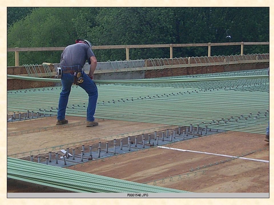
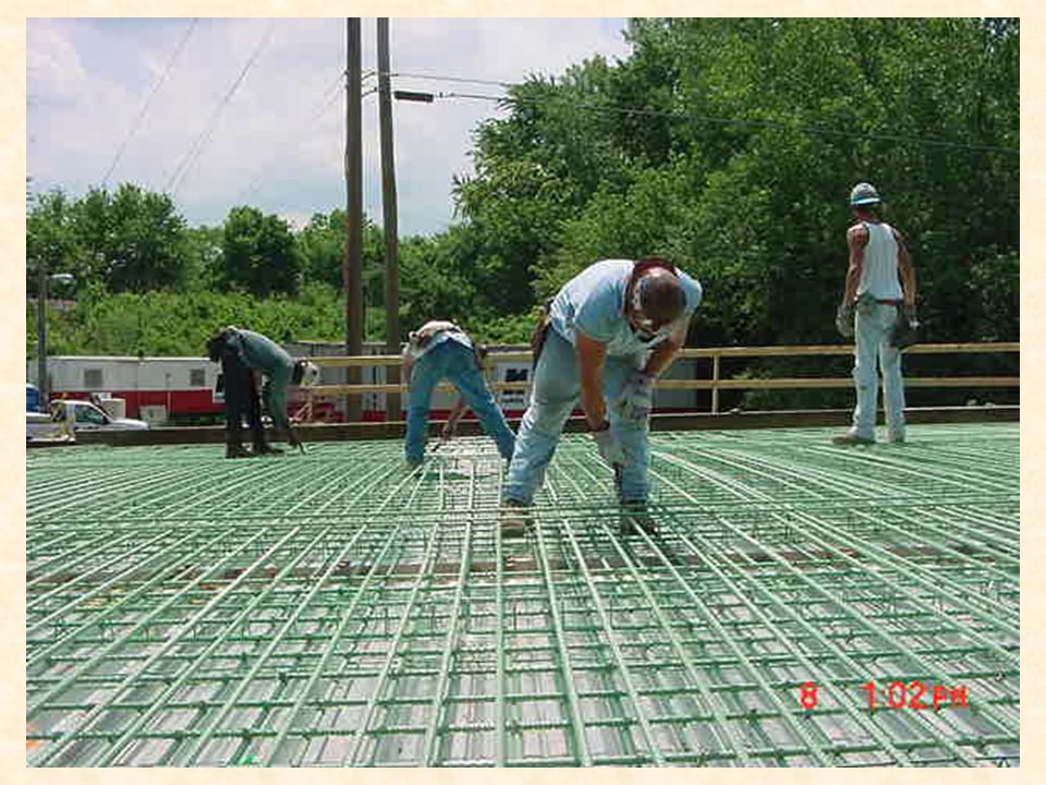
Deck forming FOR THOSE THAT HAVE NOT BEEN TO CONSTRUCTION SITE Hangers support wood joist/stringers timbers that plywood sit on

25
Deck cantilever

26
Shear connectors

31
Concrete testing

33
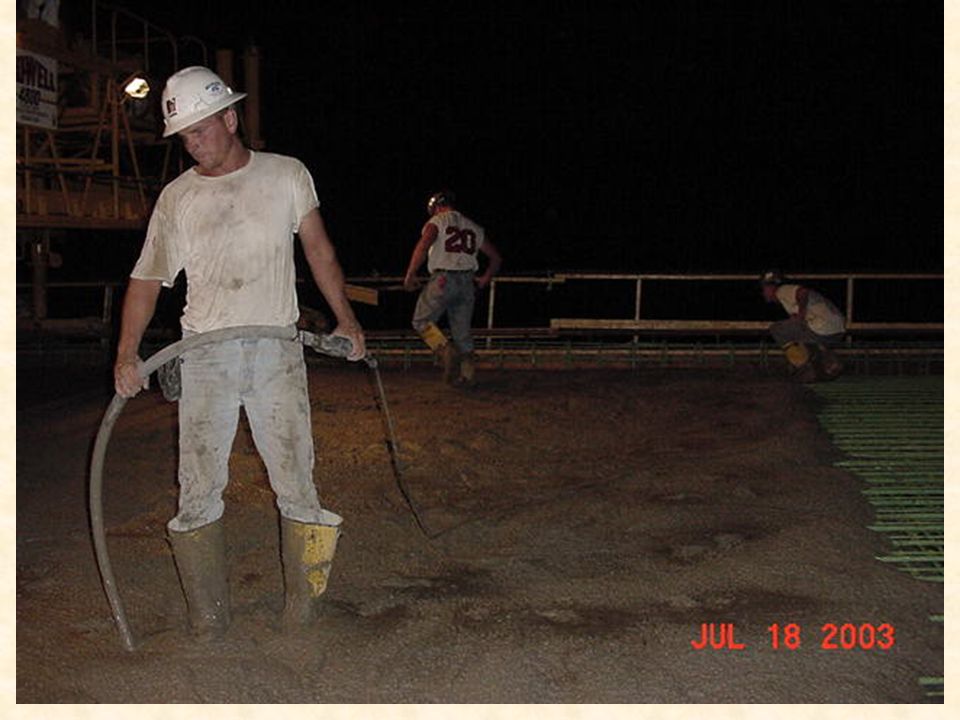
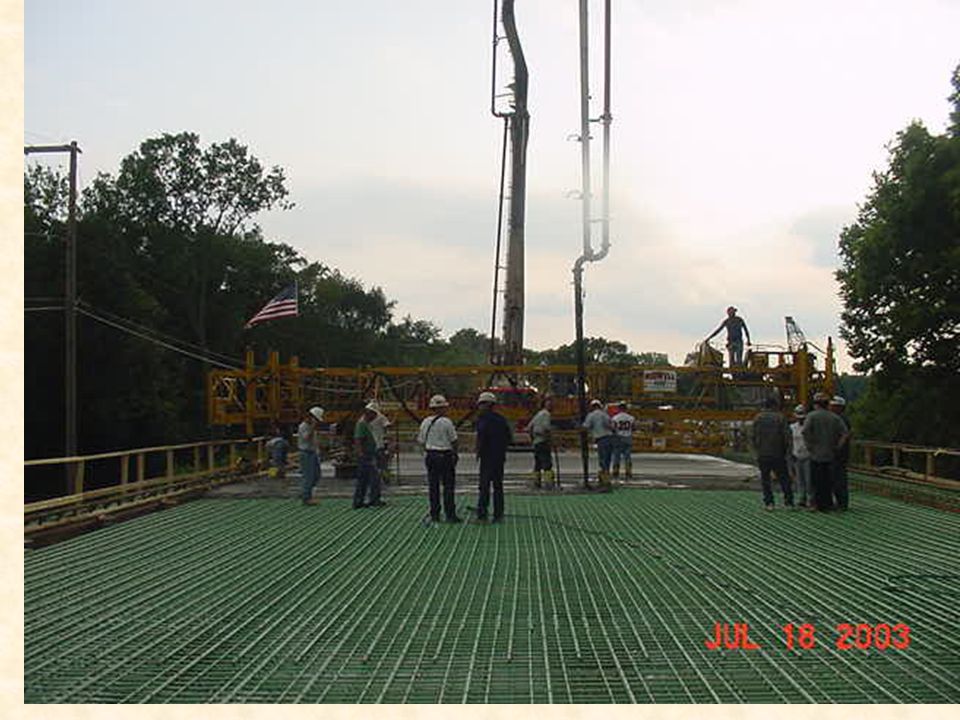
Concrete placement

39
Sidewalk

41
Deck grooving

Similar presentations


 Superstructure – Concrete Bridges>")


