Download presentation
Presentation is loading. Please wait.

1
Specificities of Calorimeter data The zero-suppress in ECAL/HCAL is 2D : 3X3 cluster => keep the 8 cells around a seed with pt > pt threshold. This cannot be done in front end boards (or Tell1) => done in the computer farmThe zero-suppress in ECAL/HCAL is 2D : 3X3 cluster => keep the 8 cells around a seed with pt > pt threshold. This cannot be done in front end boards (or Tell1) => done in the computer farm To reduce the data use packing => for small energies in cell send only 4-5 bits of 12 bit ADC. Send also bitmap of which ADC are short which are long.To reduce the data use packing => for small energies in cell send only 4-5 bits of 12 bit ADC. Send also bitmap of which ADC are short which are long. This means there is much less difference of data length from event to event compared to other detectorsThis means there is much less difference of data length from event to event compared to other detectors However we can decide to send zero data ( or only BXID +Flag) when the BXID correspond to empty beam collision.However we can decide to send zero data ( or only BXID +Flag) when the BXID correspond to empty beam collision. February 11th 2010Jacques Lefrancois1
 => done in the computer farmThe zero-suppress in ECAL/HCAL is 2D : 3X3 cluster => keep the 8 cells around a seed with pt > pt threshold. This cannot be done in front end boards (or Tell1) => done in the computer farm To reduce the data use packing => for small energies in cell send only 4-5 bits of 12 bit ADC. Send also bitmap of which ADC are short which are long.To reduce the data use packing => for small energies in cell send only 4-5 bits of 12 bit ADC. Send also bitmap of which ADC are short which are long. This means there is much less difference of data length from event to event compared to other detectorsThis means there is much less difference of data length from event to event compared to other detectors However we can decide to send zero data ( or only BXID +Flag) when the BXID correspond to empty beam collision.However we can decide to send zero data ( or only BXID +Flag) when the BXID correspond to empty beam collision. February 11th 2010Jacques Lefrancois1.")
2
February 11th 2010Jacques Lefrancois2 Digital specification Keep signal treatment ( dynamic pedestal subtraction)Keep signal treatment ( dynamic pedestal subtraction) Keep present trigger construction ( may serve as seed)Keep present trigger construction ( may serve as seed) Save space => 8 channels/FPGASave space => 8 channels/FPGA Decrease Fiber number by data compression in FE cards FPGADecrease Fiber number by data compression in FE cards FPGA It is not possible to send all data of one card into 2 fibers. 3 fibers is very difficult => choose 4fibers/card =>one fiber/FPGA as the most straightforward solution. Find FPGA without ProAsic-Plus problems => proto test with A3PE1500Find FPGA without ProAsic-Plus problems => proto test with A3PE1500

3
February 11th 2010Jacques Lefrancois3 Format of output for 8 ADCs The data format every 25ns is from 8bytes to 16 bytes longThe data format every 25ns is from 8bytes to 16 bytes long Code on short or long data for each ADC (If ADC output between pedestal-8 and pedestal+ 23 => code ADC on 5 bits.Code on short or long data for each ADC (If ADC output between pedestal-8 and pedestal+ 23 => code ADC on 5 bits. Presently in TELL1 we use 4bits to code short ADC => at higher luminosity and larger pile-up this does not work. The justification for 5bits is given slide 23,24,25,26 of http://indico.cern.ch/getFile.py/access?contribId=4&sessionId=1&resId=1& materialId=slides&confId=59892 or next slidehttp://indico.cern.ch/getFile.py/access?contribId=4&sessionId=1&resId=1& materialId=slides&confId=59892 If N ADC output smaller or larger than limit => give the full 12 bits i.e. transmit also N X (12-5) = N X 7 but because of byte organisation => N X 8 bits If N ADC output smaller or larger than limit => give the full 12 bits i.e. transmit also N X (12-5) = N X 7 but because of byte organisation => N X 8 bits 1byte for the map of 8 short or long ADC1byte for the map of 8 short or long ADC 5bytes for the data of 8 short ADC5bytes for the data of 8 short ADC up to 8 bytes for long ADC up to 8 bytes for long ADC
 = N X 7 but because of byte organisation => N X 8 bits If N ADC output smaller or larger than limit => give the full 12 bits i.e. transmit also N X (12-5) = N X 7 but because of byte organisation => N X 8 bits 1byte for the map of 8 short or long ADC1byte for the map of 8 short or long ADC 5bytes for the data of 8 short ADC5bytes for the data of 8 short ADC up to 8 bytes for long ADC up to 8 bytes for long ADC.")
4
February 11th 2010Jacques Lefrancois4 MonteCarlo results on long ADC data(ADC>25) 2X10 32 5X10 32 10X10 32 20X10 32 8ADC 256 events could be 2048 long ADC, should be about <512 Red =number of long ADC out of 2048 blue = rms
 2X X X X ADC 256 events could be 2048 long ADC, should be about <512 Red =number of long ADC out of 2048 blue = rms")
5
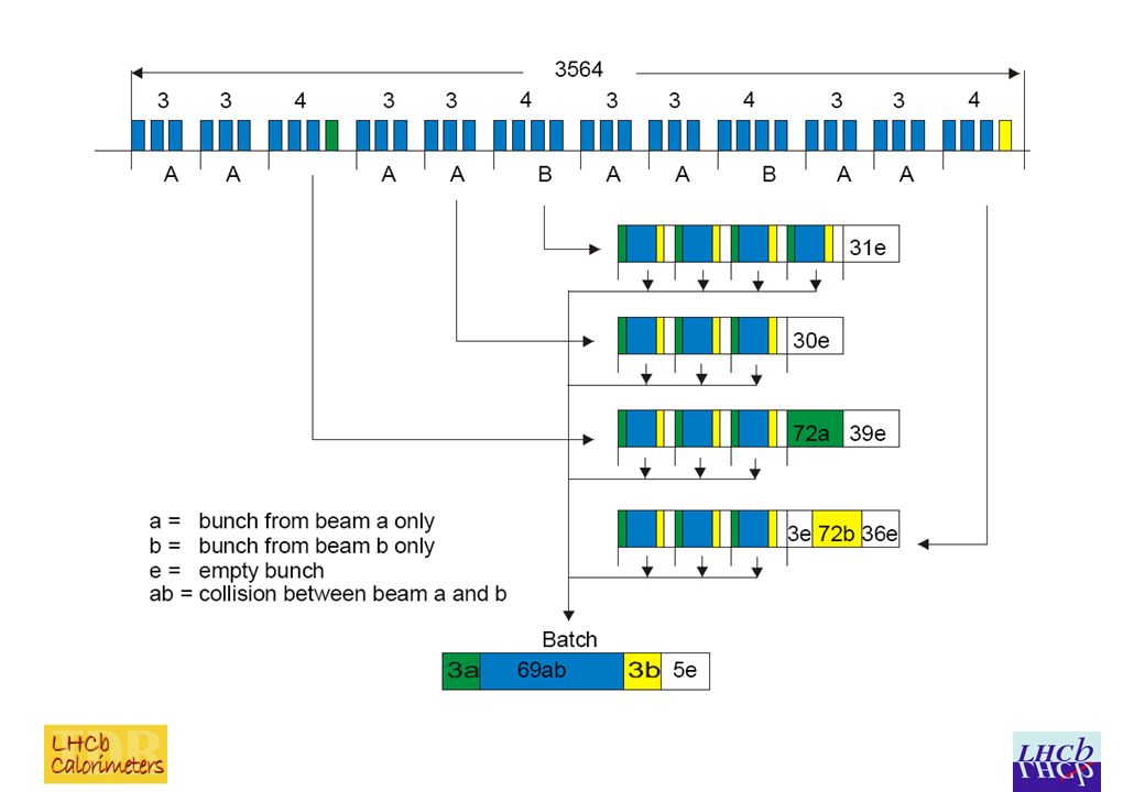
February 11th 2010Jacques Lefrancois5 Empty bunches For beam-beam collisions the data is 8 to 16 bytes with on average room for 10 bytes/25 ns in the fiberFor beam-beam collisions the data is 8 to 16 bytes with on average room for 10 bytes/25 ns in the fiber The role of the empty bunch crossing with 0 (or 2?) bytes of data is essential in giving on average enough room in the fiberThe role of the empty bunch crossing with 0 (or 2?) bytes of data is essential in giving on average enough room in the fiber The structure is typically 69 beam-beam followed by 11 empty bunch crossing.The structure is typically 69 beam-beam followed by 11 empty bunch crossing. Every 3 or 4 group of 69+11 bunch crossing there is an added 30 empty bunch crossing.Every 3 or 4 group of 69+11 bunch crossing there is an added 30 empty bunch crossing. To evaluate the average behaviour of the packing system we average over 350 bunch crossing=> 4x(69+11) +30To evaluate the average behaviour of the packing system we average over 350 bunch crossing=> 4x(69+11) +30
 +30To evaluate the average behaviour of the packing system we average over 350 bunch crossing=> 4x(69+11) +30.")
7
February 11th 2010Jacques Lefrancois7 Format output /Data coding using RAM One byte is used for the BXIDOne byte is used for the BXID One byte is used for the seed information (highest Et cluster 2X2 in the card, which is calculated by the TRIGPGA).One byte is used for the seed information (highest Et cluster 2X2 in the card, which is calculated by the TRIGPGA). Every 25ns the data to be sent is 8 to 16 bytes longEvery 25ns the data to be sent is 8 to 16 bytes long 8bytes in fixed format and 0 to 8 additional bytes for the long ADCs.8bytes in fixed format and 0 to 8 additional bytes for the long ADCs. The aim is to pack 350 events of 8 to 16 bytes long received in 350X25ns in a fiber which can send 10 bytes every 25ns.The aim is to pack 350 events of 8 to 16 bytes long received in 350X25ns in a fiber which can send 10 bytes every 25ns. A solution was presented in June using memory manipulation. It was rather easy to understand but required 52 out of 60 blocks of RAM in the A3PE1500 and required that the RAM be operated at 160 MHzA solution was presented in June using memory manipulation. It was rather easy to understand but required 52 out of 60 blocks of RAM in the A3PE1500 and required that the RAM be operated at 160 MHz

8
February 11th 2010Jacques Lefrancois8 Multiplexer solution After discussions with Federico and Richard it seems than another packing implementation is possible.After discussions with Federico and Richard it seems than another packing implementation is possible. It requires a massive use of A3PE cells used as multiplexer, demultiplexers. It can run at 40-80 MHz and requires much less memory blocksIt requires a massive use of A3PE cells used as multiplexer, demultiplexers. It can run at 40-80 MHz and requires much less memory blocks

9
February 11th 2010Jacques Lefrancois9 Pushing zeros in the 16 bytes From the map byte the number and position of long ADC data is known for example: 00010101From the map byte the number and position of long ADC data is known for example: 00010101 The data has 8 bytes of fixed formats followed by the 8 long ADC's bytes of which in the case above 5 have zero'sThe data has 8 bytes of fixed formats followed by the 8 long ADC's bytes of which in the case above 5 have zero's In 8 pipeline steps the data can be shifted so that the non zero data are in the first 3 position. This uses 64 cells +64 registers 8 steps => 1024 cellsIn 8 pipeline steps the data can be shifted so that the non zero data are in the first 3 position. This uses 64 cells +64 registers 8 steps => 1024 cells The first 8 bytes of fixed format have to wait =>512 registersThe first 8 bytes of fixed format have to wait =>512 registers

10
February 11th 2010Jacques Lefrancois10 Shift Scheme AAAAAAAAAAAAAAAA BCCCCCCCBCCCCCCC DEFFFFFFDEFFFFFF GHIJJJJJGHIJJJJJ KLMNOOOOKLMNOOOO PQRSTUUUPQRSTUUU VWXYZAABBBB A if bit0=1 select up otherwise select up-right B if bit 1=1 or bit0=1 select U otherwise select U-R/ C if bit1=1 select U otherwise select U-R D if bit 2=1 or bit 1=1 or bit 0=1 select U otherwise U-R/ E if bit2=1 or bit1=1 select U otherwise select U-R/ F if bit2=1 select U otherwise U-R Etc… data multiplexer

11
February 11th 2010Jacques Lefrancois11 Shift Scheme for a pattern 00010101 000101010000101010 001010100001010100 010101000010101000 101010000101010000 101010000101010000 110100000110100000 110100000110100000 111000000111000000

12
February 11th 2010Jacques Lefrancois12 Packing in the Buffer RAM (I) The Fiber Buffer RAM is 10 bytes wide and has (for example) a depth of 350. It uses 10 dual port RAM (actually each RAM is 8X512)The Fiber Buffer RAM is 10 bytes wide and has (for example) a depth of 350. It uses 10 dual port RAM (actually each RAM is 8X512) Use for the address of the RAM I,J I=0,350 J=0,9Use for the address of the RAM I,J I=0,350 J=0,9 Every 25ns the 8 to 16 data bytes have to be written in the Buffer RAMEvery 25ns the 8 to 16 data bytes have to be written in the Buffer RAM The address where each non zero byte of a data word is written is the last target address of the previous 8-16 byte word + K the byte location in the current word => I(N+1),J(N+1) = I(N),J(N) + KThe address where each non zero byte of a data word is written is the last target address of the previous 8-16 byte word + K the byte location in the current word => I(N+1),J(N+1) = I(N),J(N) + K but the adder is such that if J=9+1 => J=0 and I=I+1 (like a decimal adder)but the adder is such that if J=9+1 => J=0 and I=I+1 (like a decimal adder) This operation can take more than 25 ns but then it has to be done in pipeline fashion => OK no problem foreseenThis operation can take more than 25 ns but then it has to be done in pipeline fashion => OK no problem foreseen
The Fiber Buffer RAM is 10 bytes wide and has (for example) a depth of 350. It uses 10 dual port RAM (actually each RAM is 8X512) Use for the address of the RAM I,J I=0,350 J=0,9Use for the address of the RAM I,J I=0,350 J=0,9 Every 25ns the 8 to 16 data bytes have to be written in the Buffer RAMEvery 25ns the 8 to 16 data bytes have to be written in the Buffer RAM The address where each non zero byte of a data word is written is the last target address of the previous 8-16 byte word + K the byte location in the current word => I(N+1),J(N+1) = I(N),J(N) + KThe address where each non zero byte of a data word is written is the last target address of the previous 8-16 byte word + K the byte location in the current word => I(N+1),J(N+1) = I(N),J(N) + K but the adder is such that if J=9+1 => J=0 and I=I+1 (like a decimal adder)but the adder is such that if J=9+1 => J=0 and I=I+1 (like a decimal adder) This operation can take more than 25 ns but then it has to be done in pipeline fashion => OK no problem foreseenThis operation can take more than 25 ns but then it has to be done in pipeline fashion => OK no problem foreseen.")
13
February 11th 2010Jacques Lefrancois13 Packing in Buffer RAM (II) The data bytes in any of 16 position can be written in any of the 10 Rams (this is the J part of the address) this is done by 16X10 byte multiplexers (+registers?) The address I in the Buffer RAM is also calculated and has to be transmitted by multiplexers to one of the 10 RAMs (together with an eventual write enable?)The data bytes in any of 16 position can be written in any of the 10 Rams (this is the J part of the address) this is done by 16X10 byte multiplexers (+registers?) The address I in the Buffer RAM is also calculated and has to be transmitted by multiplexers to one of the 10 RAMs (together with an eventual write enable?) In some cases two bytes have to be written simultaneously at the same J at two different but successive value of I This means the RAMs run at 80MHz. The write enable should be only 12.5ns long For example the first 8 bytes of the 8-16 bytes data are written on leading edge of the 40 MHz clock the last 8 bytes on falling edge. (Using RAMs at 80 MHz =>no problem)In some cases two bytes have to be written simultaneously at the same J at two different but successive value of I This means the RAMs run at 80MHz. The write enable should be only 12.5ns long For example the first 8 bytes of the 8-16 bytes data are written on leading edge of the 40 MHz clock the last 8 bytes on falling edge. (Using RAMs at 80 MHz =>no problem) VHDL simulation to check, in coming months...VHDL simulation to check, in coming months...
In some cases two bytes have to be written simultaneously at the same J at two different but successive value of I This means the RAMs run at 80MHz. The write enable should be only 12.5ns long For example the first 8 bytes of the 8-16 bytes data are written on leading edge of the 40 MHz clock the last 8 bytes on falling edge. (Using RAMs at 80 MHz =>no problem) VHDL simulation to check, in coming months...VHDL simulation to check, in coming months....")
14
February 11th 2010Jacques Lefrancois14 Scheme for RAM transfer _ _ _ _ _ _ _ _ 5 additional colour missing: Top 16 bytes register with 8-16 bytes of data, Bottom 10bytes buffer RAM or FIFORAM, 150 byte- multiplexer for data +150 byte- multiplexer for RAM address(+write enable?) +register => about 3000 cells __ __ __ __ __
 +register => about 3000 cells __ __ __ __ __")
15
February 11th 2010Jacques Lefrancois15 Two possible type of RAMs(I) Alternate between two groups (of 10 RAMs) Alternate between two groups (of 10 RAMs) Always start a new "package of 350 events" at the top of a RAMAlways start a new "package of 350 events" at the top of a RAM Delay the readout of the RAM ( it can be after end of writing in one RAM) such that empty location in the RAM are always at the end of the group of 350 events.Delay the readout of the RAM ( it can be after end of writing in one RAM) such that empty location in the RAM are always at the end of the group of 350 events. The truncation (if there is some) is also always at the end of the group of 350 events => write a trailer 80 bits in fiber giving fiber location +truncation information + Full BXIDThe truncation (if there is some) is also always at the end of the group of 350 events => write a trailer 80 bits in fiber giving fiber location +truncation information + Full BXID The RAM system is not a FIFO it is a buffer RAM.The RAM system is not a FIFO it is a buffer RAM. The advantage is that the system is synchronous every 350,the trailer position is obvious the eventual truncation is roughly for the same BXIDs for all the calo ( all LHCb?) etc…The advantage is that the system is synchronous every 350,the trailer position is obvious the eventual truncation is roughly for the same BXIDs for all the calo ( all LHCb?) etc…
 is also always at the end of the group of 350 events => write a trailer 80 bits in fiber giving fiber location +truncation information + Full BXIDThe truncation (if there is some) is also always at the end of the group of 350 events => write a trailer 80 bits in fiber giving fiber location +truncation information + Full BXID The RAM system is not a FIFO it is a buffer RAM.The RAM system is not a FIFO it is a buffer RAM. The advantage is that the system is synchronous every 350,the trailer position is obvious the eventual truncation is roughly for the same BXIDs for all the calo ( all LHCb ) etc…The advantage is that the system is synchronous every 350,the trailer position is obvious the eventual truncation is roughly for the same BXIDs for all the calo ( all LHCb ) etc….")
16
February 11th 2010Jacques Lefrancois16 Two type of RAMs(II) Use of FIFO The RAM can be used as "standard FIFO"The RAM can be used as "standard FIFO" Read just after writing. If the FIFO is empty and if we write only 8bytes of data we send two bytes of zeros… if there was one byte left send 8 bytes + one byte of zeros. => inconvenient it is a more complicated system.Read just after writing. If the FIFO is empty and if we write only 8bytes of data we send two bytes of zeros… if there was one byte left send 8 bytes + one byte of zeros. => inconvenient it is a more complicated system. If the FIFO is not empty we write the N bytes (N=8 to 16) in the RAM as in the previous solutionIf the FIFO is not empty we write the N bytes (N=8 to 16) in the RAM as in the previous solution If too many long ADCs => FIFO full => truncate eventsIf too many long ADCs => FIFO full => truncate events Advantage: for a given size the FIFO is more resilient to a large number of long ADC (if FIFO is empty a 40 deep FIFO can almost accommodate 69 successive 8-long-ADC events= 16 bytes ).Advantage: for a given size the FIFO is more resilient to a large number of long ADC (if FIFO is empty a 40 deep FIFO can almost accommodate 69 successive 8-long-ADC events= 16 bytes ). Advantage :"it seems this is the present standard solution"Advantage :"it seems this is the present standard solution" Inconvenient: the synchronisation of the different fibers is lost! The truncation is at any BXID=> use GBT control bit for warning?Inconvenient: the synchronisation of the different fibers is lost! The truncation is at any BXID=> use GBT control bit for warning?
 in the RAM as in the previous solutionIf the FIFO is not empty we write the N bytes (N=8 to 16) in the RAM as in the previous solution If too many long ADCs => FIFO full => truncate eventsIf too many long ADCs => FIFO full => truncate events Advantage: for a given size the FIFO is more resilient to a large number of long ADC (if FIFO is empty a 40 deep FIFO can almost accommodate 69 successive 8-long-ADC events= 16 bytes ).Advantage: for a given size the FIFO is more resilient to a large number of long ADC (if FIFO is empty a 40 deep FIFO can almost accommodate 69 successive 8-long-ADC events= 16 bytes ). Advantage : it seems this is the present standard solution Advantage : it seems this is the present standard solution Inconvenient: the synchronisation of the different fibers is lost. The truncation is at any BXID=> use GBT control bit for warning Inconvenient: the synchronisation of the different fibers is lost. The truncation is at any BXID=> use GBT control bit for warning .")
17
FIFO Other uses of FIFO exist (decide to empty FIFO at the end of each 40 long empty bunches)Other uses of FIFO exist (decide to empty FIFO at the end of each 40 long empty bunches) Or stop events input by a danger flag => feedback time problem!Or stop events input by a danger flag => feedback time problem! Some Simulation test show that the event losses are very similar for the buffer system or the FIFOSome Simulation test show that the event losses are very similar for the buffer system or the FIFO For the calorimeter data At 2 X10**33 and “normal circumstance” there is a factor of 2 safety (in the number of long ADC events) before starting to loose events; this is true for all systems discussed ( Buffer RAM of 350 or 40 deep FIFO or FIFO empty each 40 empty crossings).For the calorimeter data At 2 X10**33 and “normal circumstance” there is a factor of 2 safety (in the number of long ADC events) before starting to loose events; this is true for all systems discussed ( Buffer RAM of 350 or 40 deep FIFO or FIFO empty each 40 empty crossings). February 11th 2010Jacques Lefrancois17
 before starting to loose events; this is true for all systems discussed ( Buffer RAM of 350 or 40 deep FIFO or FIFO empty each 40 empty crossings).For the calorimeter data At 2 X10**33 and normal circumstance there is a factor of 2 safety (in the number of long ADC events) before starting to loose events; this is true for all systems discussed ( Buffer RAM of 350 or 40 deep FIFO or FIFO empty each 40 empty crossings). February 11th 2010Jacques Lefrancois17.")
18
February 11th 2010Jacques Lefrancois18 Conclusion We think we can have a solution inside A3PE1500We think we can have a solution inside A3PE1500 It uses about 10-15% of the 30000 cells of the A3PE1500 but only 10-20 RAM blockIt uses about 10-15% of the 30000 cells of the A3PE1500 but only 10-20 RAM block Buffer RAM seems to have its advantage but FIFO would workBuffer RAM seems to have its advantage but FIFO would work Interesting to see the pros-cons of Buffer vs FIFO for other detectorsInteresting to see the pros-cons of Buffer vs FIFO for other detectors

Similar presentations

 Architecture of Clos Network Routing in Clos Network Blocking Rearranging.>")
 Most frames similar to previous frame.>")

 The slides included herein were taken from the materials accompanying Fundamentals.>")


>")

 Ray Mountain, Marina Artuso, Bin Gui Syracuse University OUTLINE: 1.Core 2.Peripheral 3.Testing Procedures.>")


