Download presentation
Presentation is loading. Please wait.

1
SPS flanges Simulations & Measurements Update Fritz Caspers and Jose E. Varela Acknowledgements: Jose A. Ferreira and Thomas Bohl

2
Outline Introduction Impedance List Update Damping Resistors Next Steps Conclusions

3
Introduction We continue to search for possible causes of the suspected 1.4GHz microwave instability in the SPS. Update of the impedance list with latest simulation results. Initial addressing of the damping resistor ‘problem’. Big list of next steps.

4
Outline Introduction Impedance List Update Damping Resistors Next Steps Conclusions

5
Updated Simulation Status Flange123456Total 156QF-MBA14 1513 1483 156MBA-MBA21243214 156QD-QD16 1816171699 156QF-QF Non-enamelled 55365529 156QF-QF Non-enamelled No Bellow 34224217 156QD-QD Non-enamelled 121312 141275 219BPV-QD14151615171390 219BPH-QF16/ 12 15/ 7 18/ 10 18/ 12 18/ 11 17/ 11 102/63 Analysed combinations

6
Simulations HFSS models for the enamelled BPH-QF and QF-QF flanges. QF-QF BPH-QF

7
Simulations – Total Impedance so far Flange Type EnamelBellow N um. of elements Freq. [GHz]ImpedanceQR/Q [Ω] BPH-QFYes 391.281.03MΩ4002496 QF-MBAYes 831.411.6MΩ2685985 MBA-MBAYes 141.41297kΩ2851040 QF-QFNoYes271.413.91MΩ18282140 QD-QDYesNo991.5717kΩ55317 QF-QFNo 191.61559kΩ980570 BPH-QFYes 391.62121kΩ1201014 QD-QDNo 751.8651kΩ881739 QD-QDYesNo991.89186kΩ1751070 No damping resistors included

8
Outline Introduction Impedance List Update Damping Resistors – Effect of a Short Damping Resistor – Material Properties Fitting Next Steps Conclusions

9
Damping Resistors Sextant 1Sextant 2Sextant 3Sextant 4Sextant 5Sextant 6 SSS 002 - 10205SSS 037 – 20205 OK SSS 079 – 30805 Under Vacuum SSS 109 – 40205 NO resistor SSS 151 – 50805 Ok SSS 181 – 60205 SSS 008 – 10805SSS 049 – 21405 NO Resistor SSS 097 – 32605 Ok SSS 115 – 40805 Ok SSS 155 – 51205 Ok SSS 187 – 60805 SSS 012 – 11205SSS 061 – 22605 No bellow SSS 103 – 33205 Ok SSS 119 – 41205 Ok SSS 169 – 52605 No bellow SSS 191 – 61205 SSS 025 – 12605 No bellow SSS 067 – 23205 Ok SSS 133 – 42605 Ok SSS 175 – 53205 Ok SSS 204 – 62605 SSS 031 – 13205 OK SSS 071 – 23605 Ok SSS 139 – 43205 Ok SSS 179 – 53605 Ok SSS 210 – 63205 SSS 143 – 43605 Ok For the QF-QF ‘high-Q’ flanges information about damping resistors can not be found in layouts. Jose A. Ferreira is checking the presence of damping resistors in this particular type of bellows. Most bellows have the short damping resistor as they are ‘probably’ supposed to. Two positions don’t have bellows – Outdated Layouts One position has no resistor

10
Effect of a Short Damping Resistor Enamel no Resistor Enamel Resistor Closed no Resistor Closed Resistor f [GHz]1.4151.41 (-0.35%)1.4171.411(-0.42%) Q0Q0 152791930186 Properties of the resistor can not be deduced from this measurements. The volume of the resistor represents around 1.5% of the total cavity volume. Three types of damping resistors have been provided by Jose A. Only the short one fits the available bellow.
![Effect of a Short Damping Resistor Enamel no Resistor Enamel Resistor Closed no Resistor Closed Resistor f [GHz] (-0.35%) (-0.42%) Q0Q Properties of the resistor can not be deduced from this measurements.](http://images.slideplayer.com/32/9814122/slides/slide_10.jpg "The volume of the resistor represents around 1.5% of the total cavity volume. Three types of damping resistors have been provided by Jose A. Only the short one fits the available bellow..")
11
Material Properties ‘Fitting’ Increasing Conductivity Initial damping resistor properties provided/measured by/with Thomas Bohl.

12
Material Properties ‘Fitting’ Increasing Conductivity

13
Outline Introduction Impedance List Update Damping Resistors Next Steps – Damping Resistor Survey – Additional Dangerous Elements – Pumping Port Survey – Next Measurements Set Conclusions

14
Next Steps – Damping Resistor Survey Accurate information about the presence of damping resistors all around the machine is needed. Opening all the machine to check the bellows is not feasible. Radiography could be ‘easily’ use to check the resistor presence inside bellows (Jean-Michel Dalin). – The cost of this operation depends on the specific places of the bellows. Thus we have no cost estimation.
. – The cost of this operation depends on the specific places of the bellows. Thus we have no cost estimation..")
15
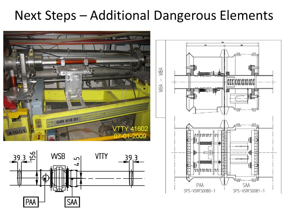
Asses additional sets of potentially dangerous elements. – There are 37 unshielded pumping ports – 23 positions (in layouts) where the ‘ensemble’ may have high impedance. – The Vacuum Valves (VVS) types A and B. Together with their surroundings. Next Steps – Additional Dangerous Elements
 where the ‘ensemble’ may have high impedance. – The Vacuum Valves (VVS) types A and B. Together with their surroundings. Next Steps – Additional Dangerous Elements.")
16
Asses additional sets of potentially dangerous elements. – There are 37 unshielded pumping ports – 23 positions (in layouts) where the ‘ensemble’ may have high impedance. – The Vacuum Valves (VVS) types A and B. Together with their surroundings. Next Steps – Additional Dangerous Elements
 where the ‘ensemble’ may have high impedance. – The Vacuum Valves (VVS) types A and B. Together with their surroundings. Next Steps – Additional Dangerous Elements.")
18
Measurement of the pumping port shields. Next Steps – Pumping Port Survey Reflection measurement sticking a probe in the ‘blade hole’. Requirements: Simulation campaign of the different scenarios, i.e. different finger misplacement for each shield type. Laboratory replica to evaluate viability and sensitivity of the measurement. Disconnection of the pump. Portable measurement equipment. Time

19
Measurement of the pumping port shields. Reflection measurement sticking a probe in the ‘blade hole’. Requirements: Simulation campaign of the different scenarios, i.e. different finger misplacement for each shield type. Laboratory replica to evaluate viability and sensitivity of the measurement. Disconnection of the pump. Portable measurement equipment. Time Next Steps – Pumping Port Survey

20
Next Steps – Next Measurements Set Measurements: – Pieces of the ‘new’ measurement set-up, MBA-MBA enamelled with bellow, were received last Tuesday. Overcome some ‘tolerance problem’ – Measurements with/without damping resistor Wire measurement Weak coupling reflection measurement Bead pull? (additional stuff required)
.")
21
Outline Introduction Impedance List Update Damping Resistors Next Steps Conclusions

22
The impedance list keeps growing as new elements are assessed. Initial estimation of the effect of damping resistors has been measured and simulated. Growing list of ‘Next Steps’ that should be done at some point.

Similar presentations


 type HP 8753D.>")


 Fermilab.>")
 Fermilab.>")


>")