Download presentation
Presentation is loading. Please wait.

1
Plasma E- Measurement Brian DeHerrera John Purcell Jaber Assiri

2
Outline Introduction ◦Purpose ◦Problems HFSS Simulation Current Design Voltage Divider Future Work & budget Conclusion

3
Purpose Create reliable current and voltage sensing equipment to work in common plasma ranges ◦>500V ◦>10MHz Create more reliable plasma for experiments ◦Control line impedance ◦Measure waveform being transmitted to plasma probe

4
Plasma System Signal Generator Amplifier Z- Scan Matching Network Plasma Probe

5
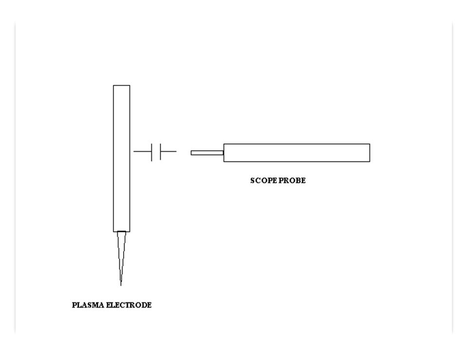
Problems No commercially available probes ◦Can meet some specifications, but not both frequency and desired voltage Not trivial to create homebrew probe ◦Needs to be high impedance ◦Parasitic

8
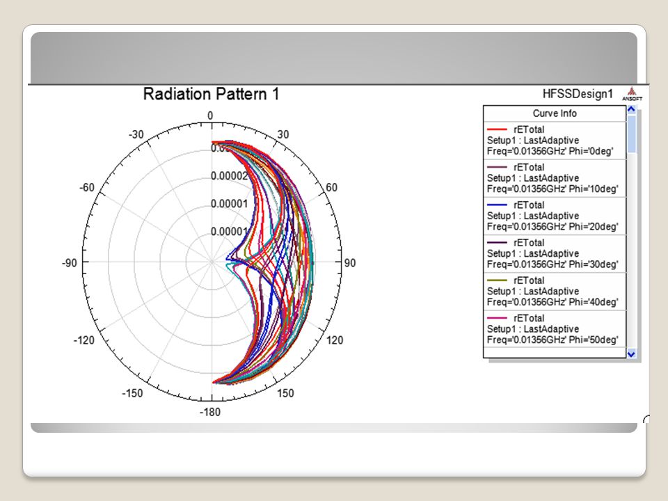
HFSS Simulation Draw Model Assign Boundary Conditions Assign Excitation Ports (inputs) Analyze Generate Reports
 Analyze Generate Reports")
9
Draw Model

10
Freq Response

12
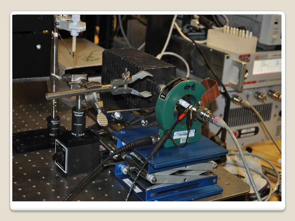
Current Design: Coax Modeled design off of AE’s Z-Scan Benefits: Parasitic are minimized Sensor can be added in-line with plasma system Concerns: EMI design: both shielding outside noise and reducing leakage Semi-complicated design ◦Need to machine parts

13
Current Design: Coax Signal Generator Amplifier Z- Scan Matching Network COAX device Plasma Probe

14
Current Design: Coax

15
Voltage Divider Why a V-D?

16
Voltage Divider Conditions: ◦R 1 +R 2 >= 2M Ohm & C 1 +C 2 <10p F Signal Generator Amplifier Z-Scan Matching Network Plas ma Prob e

17
Voltage Divider Conditions: ◦R 1 *C 1 =R 2 *C 2 If (R 1 *C 1 )> (R 2 * C 2 )
> (R 2 * C 2 )")
18
Voltage Divider Conditions: ◦R 1 *C 1 =R 2 *C 2 If (R 1 *C 1 )<(R 2 * C 2 )
<(R 2 * C 2 )")
19
Voltage Divider Conditions: ◦R 1 *C 1 =R 2 *C 2

20
Voltage Divider From: ◦R 1 +R 2 >= 2M Ohm & C 1 +C 2 <10pF & ◦R 1 *C 1 =R 2 *C 2 Therefore: ◦R 1 = 10M ohm, R 2 = 100k ohm ◦C 1 =.1pF, C 2 = 10pF

21
Future Work DateWhat will be doneCost 1/30/2010Finish the designs we have $120 2/1/2010Find more sensitive Current Transformer & probes 2/10/2010Getting some readings 2/15/2010Change the important changes in the designs $10-$20 3/1/2010Getting some results 3/30/2010Start to do the final designs $10-$50

22
Conclusion Purposes & problems HFSS Simulation Current Design Voltage Divider Future Work & budget

23
Thank you Questions ??

Similar presentations


![[ 1 ] LVDS links Servizio Elettronico Laboratori Frascati INFN - Laboratori Nazionali di Frascati G. Felici LVDS links.](/12/3729857/big_thumb.jpg "[ 1 ] LVDS links Servizio Elettronico Laboratori Frascati INFN - Laboratori Nazionali di Frascati G. Felici LVDS links.>")


>")

>")

