Download presentation
Presentation is loading. Please wait.

1
Status of VLPC Cryo-Cooler Cryostat Design Russ Rucinski (Alan Bross) Fermilab
 Fermilab")
2
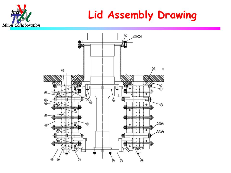
Fabrication Drawings: Drawings complete but not checked (as of 7/29) Two main assembly drawings (on next slides) u Main assembly of lid assembly to vacuum container u Lid assembly, everything that attaches to lid Detail drawings
 Two main assembly drawings (on next slides) u Main assembly of lid assembly to vacuum container u Lid assembly, everything that attaches to lid Detail drawings")
3
Main Assembly Drawing

4
Lid Assembly Drawing

6
Detail drawings (& general information about them) Invar envelope assembly – Same as previously presented, 0.015” thick invar, top flange, bottom cap. G-10 stiffener panels – 25 mm thick, dimples spaced on 12.5 mm pitch. Traps envelope on all four sides. Held together with links at ends, and bolts with belleville springs. Upper thermal link – 10 mm copper, short flex section Lower thermal link – 10 mm copper, short flex section Stiffener clamps – 12 mm thick x 20 mm in clamping direction, stainless steel. Attached with bolts & belleville springs. Lid – 24 mm thick, cable heater groove, KF40 ports Vacuum Can – 24” pipe, nothing special

7
Engineering Details Concept didn’t change since June KEK meeting. Finished up the details of the design since then. Stiffener panels had to be very stiff. Thick G- 10 with dimples fit the bill for strength and low thermal conductivity. I have a minor concern about outgassing in vacuum space. May require active pumping. Copper thermal links needed a stainless strong back (clamp) to apply 60 psi clamping pressure at cassette intercepts. Very little deflection (0.002”). Heat loads/performance did not change after design was finalized.
 to apply 60 psi clamping pressure at cassette intercepts. Very little deflection (0.002 ). Heat loads/performance did not change after design was finalized..")
8
Engineering Details Thermal links contain a flexible section of copper mesh, 10 mm thick soldered into pocket in the copper. Lower has 2 flex sections since it attaches to the intercept itself and the bottom of the envelope. Radiation heat load with MLI was 0.4 watts to upper stage, 0.6 watts to lower stage. A hard shield can be installed where easily feasible. Upper thermal clamp has tapped holes that can be used. A second gas helium port was added to give some flexibility in solving potential pressure/temperature fluctuation problems of the cassette space. The cassette space is a very small volume. One might envision a bellows bag or a continuous flow through solution.

9
Thermal Calculations – Same as June, Only the picture changed. 50 Watts @ 60 K (Total for the cryostat) 65 K Clamp bar, 77 K in Cassette 7.5 K at Clamp bar, 8.0 K in Cassette 2.8 Watts @ 6.5 K (Total for the cryostat) Lid Heater (not shown) Temperature Control heater (not shown) Thermal links G-10 panels, low conductivity
 65 K Clamp bar, 77 K in Cassette 7.5 K at Clamp bar, 8.0 K in Cassette K (Total for the cryostat) Lid Heater (not shown) Temperature Control heater (not shown) Thermal links G-10 panels, low conductivity.")
10
Thermal Calculations – (same as June) Stage 1 (~ 60 K)Stage 2 (~ 7 K) Cassette7.7 watts0.82 watts Envelope15.0 watts0.45 watts Miscellaneous2 watts0.10 watts Total per slot25 watts1.4 watts Total for cryocooler50 watts2.8 watts Operating Point 65 % capacity at 1 st stage 55% capacity at 2 nd stage
 Stage 1 (~ 60 K)Stage 2 (~ 7 K) Cassette7.7 watts0.82 watts Envelope15.0 watts0.45 watts Miscellaneous2 watts0.10 watts Total per slot25 watts1.4 watts Total for cryocooler50 watts2.8 watts Operating Point 65 % capacity at 1 st stage 55% capacity at 2 nd stage")
11
Schedule Hopefully by the time you are reading this, the detail drawings will be checked. Design drafter is very good. Should have complete drawing package by August 6. This is a delay of 2 weeks since June.

Similar presentations

MICE Absorber Status (2)MICE Absorber Modification (3)Plan/Schedule (4)Summary MICE CM-23 in HARBIN Shigeru.>")


>")


 Fermilab.>")

 2.Four final cryostats.>")


