Download presentation
Presentation is loading. Please wait.

1
Chapter 8 Secondary Memory

2
Topics Types of External Memory Magnetic Disk Optical Magnetic Tape

3
Types of External Memory 1.Magnetic Disk – Floppy – Winchester – RAID – Removable 2.Optical – CD-ROM – CD-Writable – CD-R/W – DVD 3.Magnetic Tape

4
Magnetic Disk Disk substrate coated with magnetizable material (iron oxide) Substrate used to be aluminium Now glass – Improved surface uniformity Increases reliability – Reduction in surface defects Reduced read/write errors – Better stiffness – Better shock/damage resistance
 Substrate used to be aluminium Now glass – Improved surface uniformity Increases reliability – Reduction in surface defects Reduced read/write errors – Better stiffness – Better shock/damage resistance")
5
Magnetic Disk Range of packaging – Floppy (PC’s A: drive, B: drive) – Winchester hard disk (PC’s C: drive) – Removable hard disk
 – Winchester hard disk (PC’s C: drive) – Removable hard disk")
6
Read and Write Mechanisms Recording and retrieval via conductive coil called a head. May be single read/write head or separate ones. During read/write, head is stationary, platter rotates Write – Current through coil produces magnetic field – Pulses sent to head – Magnetic pattern recorded on surface below Read (traditional) – Magnetic field moving relative to coil produces current – Coil is the same for read and write Read (contemporary) – Separate read head, close to write head – Partially shielded magneto resistive (MR) sensor – Electrical resistance depends on direction of magnetic field – High frequency operation Higher storage density and speed
 – Magnetic field moving relative to coil produces current – Coil is the same for read and write Read (contemporary) – Separate read head, close to write head – Partially shielded magneto resistive (MR) sensor – Electrical resistance depends on direction of magnetic field – High frequency operation Higher storage density and speed.")
7
Inductive Write MR Read

8
Data Organization and Formatting Concentric rings or tracks – Gaps between tracks – Reduce gap to increase capacity – Same number of bits per track (variable packing density) – Constant angular velocity Tracks divided into sectors Minimum block size is one sector May have more than one sector per block
 – Constant angular velocity Tracks divided into sectors Minimum block size is one sector May have more than one sector per block")
9
Disk Data Layout

10
Magnetic Disks

11
Originally platters were as much as 50 cm diameters!. Now: typically 3 to 12 cm ( 3cm for notebooks) Track :One complete disk rotation One track is divided into a fixed length of Sectors One Sector: typically 512 bytes of data preceded by a preamble that allows a head to be synchronized before reading or writing. Cylinder: the set of tracks at a given radial position. Following The data is an error correcting code (CRC), either a Hamming code or other types of correction. (The formatted capacity is usually 15% lower than the unformatted capacity!!)
 Track :One complete disk rotation One track is divided into a fixed length of Sectors One Sector: typically 512 bytes of data preceded by a preamble that allows a head to be synchronized before reading or writing. Cylinder: the set of tracks at a given radial position. Following The data is an error correcting code (CRC), either a Hamming code or other types of correction. (The formatted capacity is usually 15% lower than the unformatted capacity!!).")
12
Multiple Platter One head per side Heads are joined and aligned Aligned tracks on each platter form cylinders Data is striped by cylinder – reduces head movement – Increases speed (transfer rate)
")
13
Multiple Platters

14
Cylinders

15
Multiple Platter Disk Platters Surface0 Surface1 Surface7 Platter Track SpindleR/W Head (1 per surface) Cylinder Track0 Tracks Sectors Actuator
 Cylinder Track0 Tracks Sectors Actuator")
16
TECHNOLOGY With current technology: the track width depends on how large the head is and how accurately the head can be positioned radially. Disks have between 800 and 2000 tracks/cm (so track width between 5 and 10 microns range). Linear bits Density :current disks achieve densities of 50 000 to 100 000 bits/cm. Thus a bit is 50 times as big in the radial direction as along the circumference.
. Linear bits Density :current disks achieve densities of to bits/cm. Thus a bit is 50 times as big in the radial direction as along the circumference..")
17
Winchester disks: Disks with high surface and air quality since they are sealed at the factory. Disk Performance: Seek: time to take the arm to move to the right radial (actually less than 1 ms) Rotational latency: Once the head is positioned there is a delay until the desired sector rotates under the head. Average latency = (1/2) x (1/rpm) min = 30/rpm sec
 Rotational latency: Once the head is positioned there is a delay until the desired sector rotates under the head. Average latency = (1/2) x (1/rpm) min = 30/rpm sec.")
19
Disk Performance Rotation rates: 3600,5400, 7200 or 10800 RPM. (10800 RPM=180 revolutions/sec) Access time = Seek + Latency Transfer rate Time to transfer data of a sector = seek time + rotation latency + capacity of a sector transfer rate
 Access time = Seek + Latency Transfer rate Time to transfer data of a sector = seek time + rotation latency + capacity of a sector transfer rate.")
20
With a typical transfer rates of 5 to 20MB/sec, a 512-bytes sector takes between: 25 to 100 microseconds.

21
IDE Disks IDE: Integrated Drive Electronics (Having the controller closely integrated with the drive). However, BIOS calling conventions were not changed for backward compatibility. With 4 bits for the head, 6 bits for the sector and 10 bits for the cylinder (8088 assembler model), we can have a maximum of only 16 heads, 63 sectors, and 1024 cylinders!!! For a total of 1 032 192 sectors having a maximum of 528 MB! Which seemed like infinity at that time !!!
, we can have a maximum of only 16 heads, 63 sectors, and 1024 cylinders!!. For a total of sectors having a maximum of 528 MB. Which seemed like infinity at that time !!!.")
22
SOLUTION? Drives above 528 MB appeared !! EIDE: Extended IDE which supports a second addressing scheme called: LBA (Logical Block Addressing) Numbering sectors from 0 to 2 24 -1, so the controller converts LBA addresses to head, sector, cylinder addresses. So higher transfer rate and ability to control CR-ROM drives. IDE and EIDE disks were originally only for Intel-Based systems since the interface was that of IBM PC bus. However now a few other computers use them too due to their low price.
 Numbering sectors from 0 to , so the controller converts LBA addresses to head, sector, cylinder addresses. So higher transfer rate and ability to control CR-ROM drives. IDE and EIDE disks were originally only for Intel-Based systems since the interface was that of IBM PC bus. However now a few other computers use them too due to their low price..")
23
SCSI Disks SCSI: Small Computer System Interface ( pronounced: “scuzzy”) Same as IDE but have a different interface and much more higher transfer rate. Since they have higher transfer rates, they are the standard disk for most UNIX workstations from SUN, HP….. SCSI is more than just a hard disk, it’s a bus to which a SCSI controller and up to seven devices can be attached (HD’s, CD-ROM’s, CD recorders, scanners, tapes units….) Cables connect the output of one device to the input of the next one, in series.
 Cables connect the output of one device to the input of the next one, in series..")
25
exercise How long does it take to read a disk with 800 cylinders, each containing five tracks of 32 sectors? The rotation time is 20 ms, and a seek takes 10 ms between adjacent cylinders and 50 ms for the worst case. Switching between the tracks of a cylinder can be done instantaneously.

26
RAID RAID: Redundant Array of Independent Disks. The idea is to implement parallel I/O to increase CPU performance. Thus RAID is done by installing a box full of disks and replace the disk controller with a RAID controller., which looks like a SLED (Single Large Expensive Disk) to the operating system with better performance. RAID also consist of a RAID SCSI controller and a box of SCSI disks, so no software changes required to the OS to use the RAID
 to the operating system with better performance. RAID also consist of a RAID SCSI controller and a box of SCSI disks, so no software changes required to the OS to use the RAID.")
27
RAID level 0 No redundancy: simply spreading data over multiple disks, called striping. Hence Raid 0 is not really a RAID! Target: Video-editing systems

28
RAID 1: Disk Mirroring/Shadowing Each disk is fully duplicated onto its "shadow" Very high availability can be achieved Bandwidth sacrifice on write: Logical write = two physical writes Reads may be optimized Most expensive solution: 100% capacity overhead Targeted for high I/O rate, high availability environments recovery group

30
RAID 2 Error Detecting and Correcting Code Usually not used

31
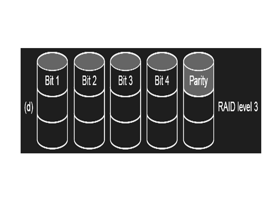
RAID 3: Bit Interleaved Parity Disk P 10010011 11001101 10010011... logical record 1001001110010011 1100110111001101 1001001110010011 0011000000110000 Striped physical records Parity computed across recovery group to protect against hard disk failures 33% capacity cost for parity in this configuration wider arrays reduce capacity costs, decrease expected availability, increase reconstruction time Arms logically synchronized, spindles rotationally synchronized logically a single high capacity, high transfer rate disk Targeted for high bandwidth applications: Scientific, Image Processing

33
D0D1D2 D3 P D0' + D1D2 D3 P' new data XOR (4. Write) (5. Write) New data 1.read 2.read 3.read Small write on RAID 3
 New data 1.read 2.read 3.read Small write on RAID 3.")
34
RAID 4: Block Interleaved Parity Disk

35
Small Writes Small Writes RAID-4 to 6 D0D1D2 D3 P D0' + + D1D2 D3 P' new data old data old parity XOR (1. Read) (2. Read) (3. Write) (4. Write) Small Write Algorithm 1 Logical Write = 2 Physical Reads + 2 Physical Writes
 (2. Read) (3. Write) (4. Write) Small Write Algorithm 1 Logical Write = 2 Physical Reads + 2 Physical Writes.")
36
Problems with RAID 4 Parity disk must be updated on every write parity disk is the bottleneck for writes. Solution: RAID 5

37
Redundant Arrays of Disks RAID 5+: High I/O Rate Parity A logical write becomes four physical I/Os Independent writes possible because of interleaved parity A logical write becomes four physical I/Os Independent writes possible because of interleaved parity D0D1D2 D3 P D4D5D6 P D7 D8D9P D10 D11 D12PD13 D14 D15 PD16D17 D18 D19 D20D21D22 D23 P.............................. Disk Columns Increasing Logical Disk Addresses Stripe Unit Targeted for mixed applications

Similar presentations


 CS-147 Fall 2010 Jonathan Wang.>")


 تنظيم الحاسب (2) 3 rd year, Computer Engineering Winter 2015 Lecture #3 Dr. Hazem Ibrahim Shehata Dept. of Computer.>")


, other innovations Final exam stats: Highest: 95 Mean: 70, Median: 73 Toughest.>")


