Download presentation
Presentation is loading. Please wait.

1
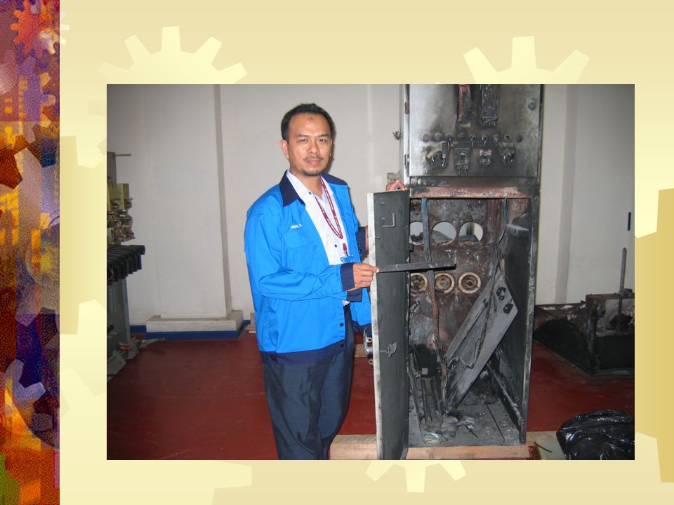
VCBs are well protected with interlocking switches for its switching device operation with busbar. Switching devices in VCBs have to be disabled or enable for raking In-Out operation for maintenance purpose. Malfunctioning of interlocking mechanism is very unlikely but if it happens the results are life threatening. There has been such failure in past and loss of life in some incidents. 1. Problem Statement PROPOSAL Automatic Rack –In & Rack-Out System for VCB

3
In view of the proximity of maintenance staff required for manual raking In-out of VCB carriage a motorized remotely controlled raking system is being proposed to eliminate personnel presence in vicinity of VCB during this operation. 2. The Solution

4
3. Design Criteria Should be able to operate on all configuration of VCB in TNB Substations Light Weight and independent Portable No altercation to VCBs functioning and operation Motorized unit with battery and charging backup Complies with IEC/ANSI/IEEE standards Raking In-Out time 10sec – 15sec Ease of accessing crank nut avoiding control devices on VCB front panel

5
3. Mechanical fixtures and fittings (schematic 1 & 2) i) Triangular mounting frame – Aluminium alloy ii) Magnetic legs – Steel rod with magnet with pull force 750 N or more. iii) Sliding and rotating arm – For alignment with crank nut port iv) Geared 24 VDC motor with encoder – 20 to 30 rpm and torque of ~250Ncm. Encoder provide distance travel by VCB. v) Adapter shaft with crank socket - To access the crank nut
 i) Triangular mounting frame – Aluminium alloy ii) Magnetic legs – Steel rod with magnet with pull force 750 N or more. iii) Sliding and rotating arm – For alignment with crank nut port iv) Geared 24 VDC motor with encoder – 20 to 30 rpm and torque of ~250Ncm. Encoder provide distance travel by VCB. v) Adapter shaft with crank socket - To access the crank nut.")
6
Schematic 1: Mechanical fixture and fittings VCB front Panel Triangular Frame Sliding Arm Magnetic legs Encoder DC Motor Gear Box Crank socket Crank nut Anchor bolt

7
Schematic 2: One possibility of triangular mounting frame

8
3. Electrical System and fixtures (Schematic 3) Control of mechanical unit is achieved by wall mounted control unit Programming Logic Controller (PLC) housed in control unit controls the operation of motor PLC reads the motor encoder and computes the distance moved by the VCB Interlocking functions of the systems will be provided from the PLC ladder logic programming Battery backup and charger will be housed in control unit The cables runs ~40m between mechanical and control units
 Control of mechanical unit is achieved by wall mounted control unit Programming Logic Controller (PLC) housed in control unit controls the operation of motor PLC reads the motor encoder and computes the distance moved by the VCB Interlocking functions of the systems will be provided from the PLC ladder logic programming Battery backup and charger will be housed in control unit The cables runs ~40m between mechanical and control units.")
9
Schematic 3: Electrical Control Unit

10
Schematic 4: Operation Flow diagram

11
4. System Specification, Testing and validation Details provided by TNB Distribution – Handout 5. Power Failure and Safety Control unit should be operational for four (4) hours from battery Thirty (30) rank In-Out operation from battery Mount or un-mount status of mechanical unit on VCB front panel 6. Material Cost i)Triangular Frame + arm+ magnetic stand RM 4000 ii)Motor + encoder + gearboxRM 2000 iii)PLC + battery + accessoriesRM 2500 iv)Cabling + connectors + socket + adaptersRM 1500 Total RM 10000 7. Development time Three (3) months from after receiving the advance money
 hours from battery Thirty (30) rank In-Out operation from battery Mount or un-mount status of mechanical unit on VCB front panel 6. Material Cost i)Triangular Frame + arm+ magnetic stand RM 4000 ii)Motor + encoder + gearboxRM 2000 iii)PLC + battery + accessoriesRM 2500 iv)Cabling + connectors + socket + adaptersRM 1500 Total RM Development time Three (3) months from after receiving the advance money.")
18
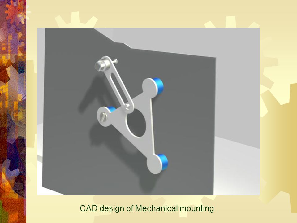
CAD design of Mechanical mounting

Similar presentations