Download presentation
Presentation is loading. Please wait.

1
The Optimum Kiln System
1) 5 stage preheater with low pressure drop cyclones 5) Oversized kiln for AFR 2) Large in-line calciner with AFR feeder 6) High momentum multi channel burner 3) Low NOx with staged TA swirl chamber 7) High efficiency cooler 8) Roller crusher 4) Hot spot (e.g. chamber) staged meal feed 10) Splined tyre fixation 9) Pneumatic seals at both ends
 5 stage preheater with low pressure drop cyclones. 5) Oversized kiln for AFR. 2) Large in-line calciner with AFR feeder. 6) High momentum multi channel burner. 3) Low NOx with staged TA swirl chamber. 7) High efficiency cooler. 8) Roller crusher. 4) Hot spot (e.g. chamber) staged meal feed. 10) Splined tyre fixation. 9) Pneumatic seals at both ends.")
2
Pre-Calciner: Typical Problems
1) CO at outlet of PC or cyclone 5) Material build-ups 6) Refractory damage 2) Locally too high temp. 7) Tertiary air damper failure 3) Unburnt fuel particles in hot meal 8) Tertiary air duct blockage (elbow type only) 4) Too high / low calcination degree
 CO at outlet of PC or cyclone. 5) Material build-ups. 6) Refractory damage. 2) Locally too high temp. 7) Tertiary air damper failure. 3) Unburnt fuel particles in hot meal. 8) Tertiary air duct blockage (elbow type only) 4) Too high / low calcination degree.")
3
Main Benefits of Precalciner Technology
1. More stable kiln operation due to better kiln control via two separate fuel feed/control points 2. More stable kiln operation due to controlled meal conditions at kiln inlet 3. Reduced thermal load of burning zone 4. Lower refractory consumption as a result of 1. to 3. 5. More than double capacities possible with given kiln (10'000 t/d: 6 x 95m) 6. Possibility of increasing capacity of existing kilns 7. Reduced volatilisation of circulating elements 8. Reduction of cycles (S, Cl, Na2O, K2O) with lower bypass rate / losses 9. Makes short kilns possible with 2 stations, L/D < 12 10. Possibilities of NOx reduction 11. Lump fuel (AFR) utilization (in-line only)
 6. Possibility of increasing capacity of existing kilns. 7. Reduced volatilisation of circulating elements. 8. Reduction of cycles (S, Cl, Na2O, K2O) with lower bypass rate / losses. 9. Makes short kilns possible with 2 stations, L/D < Possibilities of NOx reduction. 11. Lump fuel (AFR) utilization (in-line only)")
4
True and Apparent Calcination Degree
True calcination degree: Degree to which the calcination is completed, i.e. extent to which the CO2 is dissociated from the CaCO3. Extremes: Raw meal 0% (LOI=35%) Clinker 100% (LOI= 0%) Apparent calcination degree: The calcination degree determined from a hot meal sample taken from the meal duct of the bottom cyclone
 Clinker 100% (LOI= 0%) Apparent calcination degree: The calcination degree determined from a hot meal sample taken from the meal duct of the bottom cyclone.")
5
Dimensioning Criteria for Precalciners
1. Gas Retention Time (for combustion in pure air) decisive for complete combustion Fuel Reactivity Gas Retention Time low > 3.5 sec medium > 2.5 high > 2.0 2. Meal Retention Time decisive for complete calcination Actual meal retention times are 6 to 12 seconds, at the above gas retention times. Calcination takes much less than that which means that meal retention time is not a decisive design criteria. Fuel Reactivity Examples: Low: Petrol coke Medium: Bituminous coal, natural gas High: Lignite, fuel oil Inline Calciners: Due to less favourable conditions for combustion (presence of kiln gas, imperfect mixing of tertiary air with kiln gas), the following rule of thumb can be used for sizing this PC type: Recommended gas retention time to 1 sec
 decisive for complete combustion. Fuel Reactivity. Gas Retention Time. low. > 3.5. sec. medium. > 2.5. high. > Meal Retention Time. decisive for complete calcination. Actual meal retention times are 6 to 12 seconds, at the above gas retention times. Calcination takes much less than that which. means that meal retention time is not a. decisive design criteria. Fuel Reactivity Examples: Low: Petrol coke. Medium: Bituminous coal, natural gas. High: Lignite, fuel oil. Inline Calciners: Due to less favourable conditions for combustion. (presence of kiln gas, imperfect mixing of. tertiary air with kiln gas), the following rule of. thumb can be used for sizing this PC type: Recommended gas retention time to 1 sec.")
6
Cyclone Preheater: Typical Problems
1) Dip tube missing or damaged 5) Too high velocity 6) Meal flaps not working 2) False air 7) Thermocouple bad location 3) Meal deposit 8) Splash plate worn; splash box not clean 4) Cyclone blockage
 Dip tube missing or damaged. 5) Too high velocity. 6) Meal flaps not working. 2) False air. 7) Thermocouple bad location. 3) Meal deposit. 8) Splash plate worn; splash box not clean. 4) Cyclone blockage.")
7
Counter-Current Heat Exchange

8
Co-Current Heat Exchange

9
Energy Turnover in a Grate Cooler

10
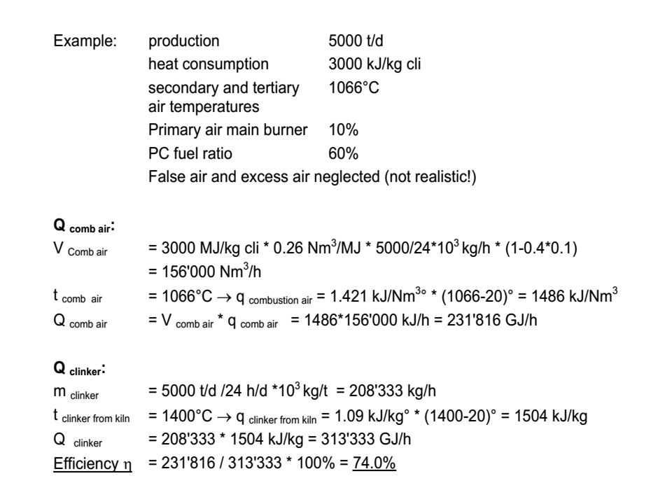
Cooler Efficiency h cooler
Q combustion air S Q loss h cooler = = Q clinker from kiln S Q clinker from kiln

12
Tube Cooler

13
Problems of Conventional Grate Coolers
Uneven clinker distribution “Red River” Air breaking through (“Geyser”) Overheated / burnt plates Thin clinker bed Poor UG-compartment sealing -> Poor recuperation (low hth)
 Overheated / burnt plates. Thin clinker bed. Poor UG-compartment sealing. -> Poor recuperation (low hth)")
14
Benefits of Modern Cooler Technology
Smoother cooler operation More stable kiln operation Good recuperation (high hth) Control of “Red River” Less or no clinker fall through Smaller waste air system Less space required (Lower power consumption)
 Control of Red River Less or no clinker fall through. Smaller waste air system. Less space required. (Lower power consumption)")
15
Fixed Grate Coolers SF Crossbar Cooler (FLS Fuller) Main Features
First radically different grate cooler! Fixed line; no moving rows Mechanical flow regulators; 1 per plate Crossbars for clinker conveying Standard modules; pre-installed Different speeds across width possible Size < 45 t/d m2 Air installed: ~2.0 Nm3/kg

16
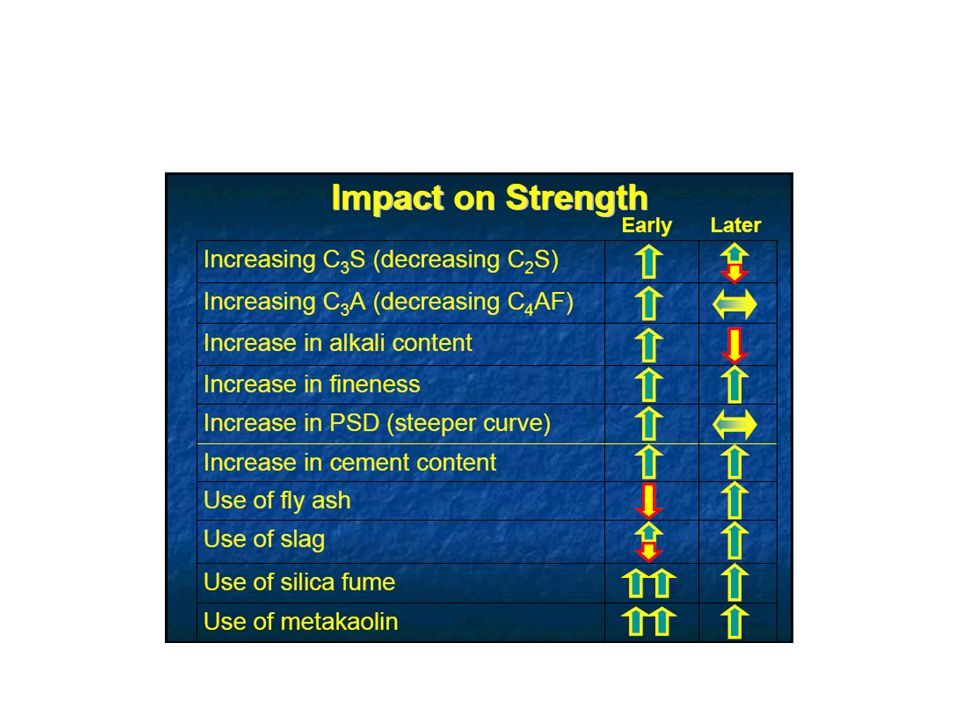
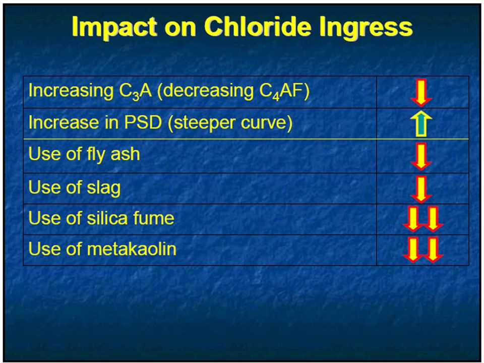
Influence on clinker composition Influence on burning process
Influence of Ratio on burning Process and Chemical Composition Influence on clinker composition Influence on burning process Up and down Ratio C3A C4AF C3A C4AF C3S C2S Free lime will increase C3S C2S Difficult to burnا Lower Clinkering Temperature Lower clinker Clinker reaction accelerated Difficult to burn Easy to burn high Low High 1-Silica ratio SiO2 = Al2O3+ Fe2O3 2-Alumina ratio = Al2O3 Fe2O3 3-Lime saturation factor = CaO 2.8SiO Al2O3+0.65Fe2O3 Or 2.8 SiO2+0.65Al2O3+.35Fe2O

21
5 Stages of Hydration Reaction Stage Kinetics of Reaction
4/26/2017 6:53 AM 5 Stages of Hydration Reaction Stage Kinetics of Reaction Chemical Process 1. Initial hydrolysis Chemical Control : Rapid Dissolution of Ions 2. Induction Period Nucleation control : low Continued dissolution of ions 3. Acceleration Initial formation of hydration products 4. Deceleration Chemical and diffusion control : Slow Continued formation of hydration products 5. Steady State Diffusion control : Slow Slow formation of hydration products © 2007 Microsoft Corporation. All rights reserved. Microsoft, Windows, Windows Vista and other product names are or may be registered trademarks and/or trademarks in the U.S. and/or other countries. The information herein is for informational purposes only and represents the current view of Microsoft Corporation as of the date of this presentation. Because Microsoft must respond to changing market conditions, it should not be interpreted to be a commitment on the part of Microsoft, and Microsoft cannot guarantee the accuracy of any information provided after the date of this presentation. MICROSOFT MAKES NO WARRANTIES, EXPRESS, IMPLIED OR STATUTORY, AS TO THE INFORMATION IN THIS PRESENTATION.

22
4/26/2017 6:53 AM Stage 5: Densification/ Steady Stage (can continue for years) Start of belite reactions and they can continue for years. Belite reactions also produce C-S-H and CH, forming a solid mass. Longer length of this stage gives: •Greater concrete’s strength •Lower permeability •Greater durability To promote continued hydration, moisture must be retained in the slab as long as possible © 2007 Microsoft Corporation. All rights reserved. Microsoft, Windows, Windows Vista and other product names are or may be registered trademarks and/or trademarks in the U.S. and/or other countries. The information herein is for informational purposes only and represents the current view of Microsoft Corporation as of the date of this presentation. Because Microsoft must respond to changing market conditions, it should not be interpreted to be a commitment on the part of Microsoft, and Microsoft cannot guarantee the accuracy of any information provided after the date of this presentation. MICROSOFT MAKES NO WARRANTIES, EXPRESS, IMPLIED OR STATUTORY, AS TO THE INFORMATION IN THIS PRESENTATION.
 Start of belite reactions and they can continue for years. Belite reactions also produce C-S-H and CH, forming a solid mass. Longer length of this stage gives: •Greater concrete’s strength •Lower permeability •Greater durability To promote continued hydration, moisture must be retained in the slab as long as possible. © 2007 Microsoft Corporation. All rights reserved. Microsoft, Windows, Windows Vista and other product names are or may be registered trademarks and/or trademarks in the U.S. and/or other countries. The information herein is for informational purposes only and represents the current view of Microsoft Corporation as of the date of this presentation. Because Microsoft must respond to changing market conditions, it should not be interpreted to be a commitment on the part of Microsoft, and Microsoft cannot guarantee the accuracy of any information provided after the date of this presentation. MICROSOFT MAKES NO WARRANTIES, EXPRESS, IMPLIED OR STATUTORY, AS TO THE INFORMATION IN THIS PRESENTATION.")
23
4/26/2017 6:53 AM Factors Affecting Hydration Major factors :- • Chemical Composition of Cement • Cement Type • Sulfate Content • Fineness • Water/Cement Ratio • Curing Temperature • Effects of SCMs and Admixtures © 2007 Microsoft Corporation. All rights reserved. Microsoft, Windows, Windows Vista and other product names are or may be registered trademarks and/or trademarks in the U.S. and/or other countries. The information herein is for informational purposes only and represents the current view of Microsoft Corporation as of the date of this presentation. Because Microsoft must respond to changing market conditions, it should not be interpreted to be a commitment on the part of Microsoft, and Microsoft cannot guarantee the accuracy of any information provided after the date of this presentation. MICROSOFT MAKES NO WARRANTIES, EXPRESS, IMPLIED OR STATUTORY, AS TO THE INFORMATION IN THIS PRESENTATION.

24
4/26/2017 6:53 AM Mechanism of Heat generation Reaction of calcium Silicates : 2 C3S + 7H C3S2H8 + 3CH H= J/g 2 C2S + 7H C3S2H8 + CH H= J/g Reaction of tri calcium aluminate C3A + 3 CSH H C6AS3H H = J/g © 2007 Microsoft Corporation. All rights reserved. Microsoft, Windows, Windows Vista and other product names are or may be registered trademarks and/or trademarks in the U.S. and/or other countries. The information herein is for informational purposes only and represents the current view of Microsoft Corporation as of the date of this presentation. Because Microsoft must respond to changing market conditions, it should not be interpreted to be a commitment on the part of Microsoft, and Microsoft cannot guarantee the accuracy of any information provided after the date of this presentation. MICROSOFT MAKES NO WARRANTIES, EXPRESS, IMPLIED OR STATUTORY, AS TO THE INFORMATION IN THIS PRESENTATION.

Similar presentations


>")


>")


 but, impurities are always present: MgCO 3,Al 2 O.>")


