Download presentation
Presentation is loading. Please wait.

1
© 2009, Renesas Technology America, Inc., All Rights Reserved 1 Course Introduction Purpose This course provides an introduction to the peripheral functions built into R8C Tiny series microcontrollers (MCUs). Objective Learn about the features and operation of the TimerRA, TimerRB, TimerRC, TimerRD and TimerRE functions. Understand the basics of the Watchdog Timer. Discover how the Power-on Reset (POR) and Low-Voltage Detect (LVD) functions operate. Content 33 pages 6 questions Learning Time 35 minutes
 and Low-Voltage Detect (LVD) functions operate. Content 33 pages 6 questions Learning Time 35 minutes.")
2
© 2009, Renesas Technology America, Inc., All Rights Reserved 2 Versatile Set of Timers The Watchdog Timer is covered separately in this course.

4
© 2009, Renesas Technology America, Inc., All Rights Reserved 4 Which of the following timers on the R8C family is 16bit ? Click “Done” when you are finished. Timer RA Timer RB B Done Reset Show Solution A C Timer RC Question Timer RE D

5
© 2009, Renesas Technology America, Inc., All Rights Reserved 5 Timer RA

6
© 2009, Renesas Technology America, Inc., All Rights Reserved 6 Timer RB

7
© 2009, Renesas Technology America, Inc., All Rights Reserved 7 Timer RC

8
© 2009, Renesas Technology America, Inc., All Rights Reserved 8 Timer RD

9
© 2009, Renesas Technology America, Inc., All Rights Reserved 9 Timer RE

10
© 2009, Renesas Technology America, Inc., All Rights Reserved 10 FF Timer Mode FF Reload register FF 2 1 0 Count Start flag TRAPRE Pre-scalerTRA Counter Timer RA Interrupt f2 fOCO f8 f1 Count Source The timer counts an internally generated count source. Operation:When the timer underflows, it reloads the register contents before continuing to count. 1 0 1 10012 00h Timer RA Mode register Timer RA Mode Register is used to put Timer RA into the Timer Mode and start/stop the counting. 08h 0 12 Example: Timer RA

11
© 2009, Renesas Technology America, Inc., All Rights Reserved 11 Pulse Output Mode 1 Reload register 2 2 0 Count Start flag TRAPRE Pre-scalerTRA Counter f2 fOCO f8 f1 Count Source 1 Toggle flip-flop Q Q CK 01 TMOD bits The timer counts an internally generated count source, the TRAO pin outputs a pulse whose polarity is inverted when the timer underflows. Operation:When the timer underflows, it reloads the register contents before continuing to count. TRAO 1 Example: Timer RA

12
© 2009, Renesas Technology America, Inc., All Rights Reserved 12 Pulse Output Mode: Timer RA Example 1 Reload Register 2 2 0 Count Start Flag PREX registerTX register f2 fOCO f8 f1 Count Source 1 Toggle flip-flop Q Q CK 01 TMOD bits The timer counts an internally generated count source, the TRAO pin outputs a pulse whose polarity is inverted when the timer underflows. Operation:When the timer underflows, it reloads the register contents before continuing to count. CNTR0 1

14
© 2009, Renesas Technology America, Inc., All Rights Reserved 14 Question Is the following statement true or false? Click “Done” when you are finished. “The functionality of the Pulse Output Mode is exactly the same as in Timer mode, except a pulse is output on the TRAO pin.” True False Done

15
© 2009, Renesas Technology America, Inc., All Rights Reserved 15 Generate Complementary Outputs 1 Reload register 2 2 0 Count Start flag TRAPRE Pre-scalerTRA Counter f2 fOCO f8 f1 Count Source 1 Toggle flip-flop Q Q CK 01 TMOD bits 1 TRAIO TRAO TRAIO has the option to be a port pin or an inverted output of TRAO 1 Example: Timer RA

16
© 2009, Renesas Technology America, Inc., All Rights Reserved 16 Event Counter Mode FF Reload register FF 0 Count Start Flag TRAPRE Pre-scalerTRA Counter External Count Source 1 TRAIO Timer RA Mode register 00h02h 0 0 2 2 0Ah 102 Timer RA Interrupt Example: Timer RA The timer counts an external signal fed to TRAIO pin. Operation: When the timer underflows, it reloads the register contents before continuing to count. Timer RA Mode Register is use to put Timer RA into Event Counter Mode, selects the active edge of the count Source, and starts/stops the counter.

17
© 2009, Renesas Technology America, Inc., All Rights Reserved 17 Pulse Width Measurement Mode 0 Reload register 5 5 0 0 Count Start flag TRAPRE Pre-scalerTRA Counter f2 f32 f8 f1 1 TRAIO Timer RA Interrupt TRAIO pin IR bit in TRAIC register Count Stop The timer measures the pulse width of an external signal fed into the TRAIO pin. TUNDF bit in TRACR register Timer Underflow Count Source Example: Timer RA

18
© 2009, Renesas Technology America, Inc., All Rights Reserved 18 Pulse Period Measurement Mode: Timer RA TRAIO pin Underflow signal of prescaler TRA contents 0F0E0D0F0E0D0C0B0A090F0E 0F0E0D Timer RA interrupt Timer RA active Edge detected ( TEGDF bit) 0B0A 09 000F 000F Timer RA underflow (TUNDF bit) Contents of read out buffer Timer RA reloads Timer RA read Cleared to “0” by program Period being measured Timer RA reloads
 0B0A F 000F Timer RA underflow (TUNDF bit) Contents of read out buffer Timer RA reloads Timer RA read Cleared to 0 by program Period being measured Timer RA reloads")
19
© 2009, Renesas Technology America, Inc., All Rights Reserved 19 Programmable Waveform Gen. Mode FF Reload registerTRBSC register FF 1 0 Count Start flag TRBPRE Pre-scalerTimer RB Counter f2 TRA UNF f8 f1 Count Source 1 Toggle flip-flop Q Q CK 01 TMOD bits FF TRBPR register TRBO P3_1 bit 021010210FF Primary period Secondary period A signal is output from the TRBO pin which is inverted each time the counter underflows, it reloads the contents of primary reload register and secondary reload register alternately before continuing to count. 0 0 21 102101 Example: Timer RB

20
© 2009, Renesas Technology America, Inc., All Rights Reserved 20 Programmable One-Shot Gen. Mode 0 Reload register 1 1 0 0 Count Start flag TRBPRE Pre-scalerTimer RB Counter f2 TRA UDF f8 f1 Count Source 1 Toggle flip-flop Q Q CK 01 TMOD bits TRBPR register TRBO P3_2 bit 0210102101 Digital Filter Input polarity selected to be one edge or both edges Polarity select TSTART TOSSTF TMODx INT0ENINT0PL INT0 Example: Timer RB

22
© 2009, Renesas Technology America, Inc., All Rights Reserved 22 B E Done Reset Show Solution A C C B A D The input that the timer counts is an external signal that is fed into the MCU through the TRAIO pin. When a trigger occurs, the timer starts operating once for a given period. After the Count Start bit has been set, the timer waits for a high signal on the TRAIO pin. E D A signal is output from the TRBO pin and is inverted each time the counter underflows. Question Event Counter Mode Pulse Width Measurement Mode Pulse Period Measurement Mode Programmable Waveform Generator Mode Programmable One-Shot Generator Mode Match each timer mode to its function by dragging the letters on the left to their appropriate locations on the right. Click “Done” when you are finished. If an underflow occurs while the timer is counting, the TUNDF bit goes high so that the underflow can be taken into account.

23
© 2009, Renesas Technology America, Inc., All Rights Reserved 23 Generating a Precise Pulse Width 010001 Contents of TRA TSTART bit in TRACR register Output of TRAO out pin Pre-scaler RA underflow signal Count Source IR bit in TRAIC register Count Starts Waveform Output Starts Waveform Output ends Timer RA primary reloads Set to “1” by program Set to “0” by program

24
© 2009, Renesas Technology America, Inc., All Rights Reserved 24 Programmable Wait One Shot Generation Mode: Timer RB In this mode, upon program or external trigger input, the device outputs the one-shot pulse from the TRBO pin after waiting for a given length of time. When a trigger occurs, the timer starts outputting a pulse for a given length of time equal to the set value in the TRBSC register. This is only after waiting for the TRBPR register to overflow. 010002 Count Source Timer RB One Shot bit Contents of TRBPR Prescaler RB underflow signal Interrupt Request bit in Timer RB Interrupt Control register TRBO out pin 010001 Set to “1” by program, or set to “1” by INT0 pin input trigger Set to “0” when counting completed Count Starts Timer RB secondary reloads Timer RB primary reloads Waveform output starts Waveform output end Wait starts

25
© 2009, Renesas Technology America, Inc., All Rights Reserved 25 Input Capture Mode

26
© 2009, Renesas Technology America, Inc., All Rights Reserved 26 TimerRC Timer Mode Output Compare

27
© 2009, Renesas Technology America, Inc., All Rights Reserved 27 TimerRC PWM Mode

28
© 2009, Renesas Technology America, Inc., All Rights Reserved 28 TimerRD Complementary PWM Mode

29
© 2009, Renesas Technology America, Inc., All Rights Reserved 29 TimerRD Complementary PWM Mode

31
© 2009, Renesas Technology America, Inc., All Rights Reserved 31 Match the timer operating mode to one of its applications by dragging the letters on the left to their appropriate locations on the right. Click “Done” when you are finished. Input Capture mode (Timer RC) Programmable One Shot Generation mode (Timer RB) B B Done Reset Show Solution A Useful for determining the duration of an event C C Pulse Width Measurement mode (Timer RA) Can be used to generate a pulse that has a precise, program-controlled width D Useful in motor control applications Question Programmable Waveform Generation mode (Timer RB) D Could be used to measure the speed of a conveyor belt A
 Programmable One Shot Generation mode (Timer RB) B B Done Reset Show Solution A Useful for determining the duration of an event C C Pulse Width Measurement mode (Timer RA) Can be used to generate a pulse that has a precise, program-controlled width D Useful in motor control applications Question Programmable Waveform Generation mode (Timer RB) D Could be used to measure the speed of a conveyor belt A.")
32
© 2009, Renesas Technology America, Inc., All Rights Reserved 32 Watchdog Timer 1/16 1/128 Watchdog Timer Interrupt Request Watchdog Timer Reset PM12 = 0 PM12 = 1 WDC7 = 0 WDC7 = 1 Set to 7FFF 16 Write to WDTS register RESET CPU Clock Pre-scaler Watchdog Timer The WDT circuit contains a 15-bit counter that counts down the clock derived by dividing the CPU clock by 16 or 128 using the pre-scaler.

33
© 2009, Renesas Technology America, Inc., All Rights Reserved 33 Power-On Reset Function CPU Res et IC CPU Res et IC Reset CCT No External Reset IC required 0.5 Vdet 5.0 time Internal state in Reset CPU ResetReset Released (1/f(RING)) X 32 Vdet = 3.8V ± 0.5V More Than 1ms VCC [V] S R Q 5-bit counter Internal RESET signal RESET fRING-S VCC > Vdet detection trigger 5KΩ
![© 2009, Renesas Technology America, Inc., All Rights Reserved 33 Power-On Reset Function CPU Res et IC CPU Res et IC Reset CCT No External Reset IC required 0.5 Vdet 5.0 time Internal state in Reset CPU ResetReset Released (1/f(RING)) X 32 Vdet = 3.8V ± 0.5V More Than 1ms VCC [V] S R Q 5-bit counter Internal RESET signal RESET fRING-S VCC > Vdet detection trigger 5KΩ](http://images.slideplayer.com/27/9144179/slides/slide_33.jpg "© 2009, Renesas Technology America, Inc., All Rights Reserved 33 Power-On Reset Function CPU Res et IC CPU Res et IC Reset CCT No External Reset IC required 0.5 Vdet 5.0 time Internal state in Reset CPU ResetReset Released (1/f(RING)) X 32 Vdet = 3.8V ± 0.5V More Than 1ms VCC [V] S R Q 5-bit counter Internal RESET signal RESET fRING-S VCC > Vdet detection trigger 5KΩ")
34
© 2009, Renesas Technology America, Inc., All Rights Reserved 34 Low Voltage Detect Function 2.7 Vdet 5.0 time Internal state in Reset CPU Reset Reset Released (1/f(RING)) X 32 Vdet = 3.8V ± 0.5V VCC [V] Reset Released The operation of the LVD function is essentially the same as the operation of the POR.
![© 2009, Renesas Technology America, Inc., All Rights Reserved 34 Low Voltage Detect Function 2.7 Vdet 5.0 time Internal state in Reset CPU Reset Reset Released (1/f(RING)) X 32 Vdet = 3.8V ± 0.5V VCC [V] Reset Released The operation of the LVD function is essentially the same as the operation of the POR.](http://images.slideplayer.com/27/9144179/slides/slide_34.jpg "© 2009, Renesas Technology America, Inc., All Rights Reserved 34 Low Voltage Detect Function 2.7 Vdet 5.0 time Internal state in Reset CPU Reset Reset Released (1/f(RING)) X 32 Vdet = 3.8V ± 0.5V VCC [V] Reset Released The operation of the LVD function is essentially the same as the operation of the POR.")
35
© 2009, Renesas Technology America, Inc., All Rights Reserved 35 LVD Operation Voltage Detect Enable 5.0 V Vdet Sampling time 3 to 4 clocks (1/f(RING)) X 32 Internal Reset Signal Voltage Detect Flag Voltage Detect Interrupt Request Sampling time 3 to 4 clocks VCC Interrupt Acknowledge 5.0 V
) X 32 Internal Reset Signal Voltage Detect Flag Voltage Detect Interrupt Request Sampling time 3 to 4 clocks VCC Interrupt Acknowledge 5.0 V")
37
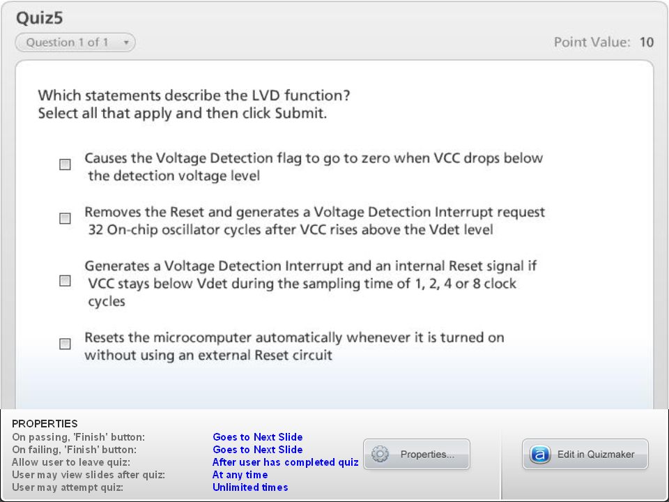
© 2009, Renesas Technology America, Inc., All Rights Reserved 37 Which statements describe the LVD function? Select all that apply and then click Done. Causes the Voltage Detection flag to go to zero when VCC drops below the detection voltage level Generates a Voltage Detection Interrupt and an internal Reset signal if VCC stays below Vdet during the sampling time of 1, 2, 4 or 8 clock cycles Removes the Reset and generates a Voltage Detection Interrupt request 32 On-chip oscillator cycles after VCC rises above the Vdet level Resets the microcomputer automatically whenever it is turned on without using an external Reset circuit Done Question

38
© 2009, Renesas Technology America, Inc., All Rights Reserved 38 Timer functions Timer modes Watchdog timer Power-On Reset function Low Voltage Detect function Course Summary http://www.renesasinteractive.com

Similar presentations


.>")
>")
, used to bring down the frequency to the desired level.>")

 or disable.>")

