Download presentation
Presentation is loading. Please wait.

1
Final Presentation Encryption on Embedded System Supervisor: Ina Rivkin students: Chen Ponchek Liel Shoshan Spring 2014 Part B

2
Motivation Now days, there are many portable storage systems with large memories which contains valuable data (such as disk on key, tablets, etc.) Therefore there is a concrete need for portable cryptography systems which are suitable for such devices. In our project, we will aspire to provide a suitable system which will answer this need.

3
Project Goal main goal: Implementation of efficient data cryptography embedded system using AES algorithm and finding the suitable architecture for portable system.

4
Project Specifications Implementing on a Zync SOC by Xilinx. Suitable for portable systems (Disk-on-Key, tablets, etc.) - low power system. Transparent system (while storing/loading files) - The cryptography system won’t create traffic bottle necks. Finding the best architecture - according to the requirements above: Profiling AES algorithm. Finding the balance between using the ARM processor and using the FPGA (the hardware accelerator needs more power).
 - low power system. Transparent system (while storing/loading files) - The cryptography system won’t create traffic bottle necks. Finding the best architecture - according to the requirements above: Profiling AES algorithm. Finding the balance between using the ARM processor and using the FPGA (the hardware accelerator needs more power)..")
5
AES Algorithm Advanced Encryption Standard, also known as “Rijndael”, is a block cipher. The cipher is iterative, quick and comfortable to implement both by software and hardware, and it doesn’t have high memory requirements. Most of the AES calculations are made through 10 rounds. The Key Expansion Schedule creates 10 Round Keys from the initial cipher key. In each round the state block is described as a 2D, 4X4 array of bytes. Each round consists of 4 steps: 1.SubBytes 2.ShiftRows 3.MixColumns 4.AddRoundKey KeyExpansion Key

6
System Top View zedboard DDR ARM PS software Programmable Logic hardware UART AXI4-bus BRAM

7
PS UART RS232 PL ZEDBOARD Encrypted data Decrypted data Zynq AES in software System Block Diagram project part A Implementation of AES algorithm on ARM and code optimization. DDR BRAM

8
Software Implementation Each step is implemented as a separate function. Each function is independent of the other functions. Code optimizations improved performance significantly. The encryption rate we achieved was 323 KB/s. 1.5 times slower than the typical maximum data rate in USB (The typical rates are around 0.5 MB/s.) Conclusion: A hardware accelerator is needed.
 Conclusion: A hardware accelerator is needed..")
9
Software Profiling Distribution of software’s running time by functions

10
Software Implementation Profiling Encryption Time-Split KeyExpansion Key

11
Hardware/Software Balancing The most time consuming function is Mix Columns. Concurrency can be achieved by running Key Expansion and the encryption process simultaneously. To minimize data traffic between PS and PL, Add Round Key should be implemented in hardware.

12
Integrated System Block diagram zedboard DDR ARM PS software Programmable Logic hardware AXI4-bus Add Round Key Shift Rows Key Expansion Mix Columns Sub Bytes UART

13
Integrated System Flow Diagram SubBytes ShiftRows AddRoundKey KeyExpansion ARM PS software Programmable Logic hardware x 9 Key MixColumns AddRoundKey SubBytes ShiftRows AddRoundKey State

14
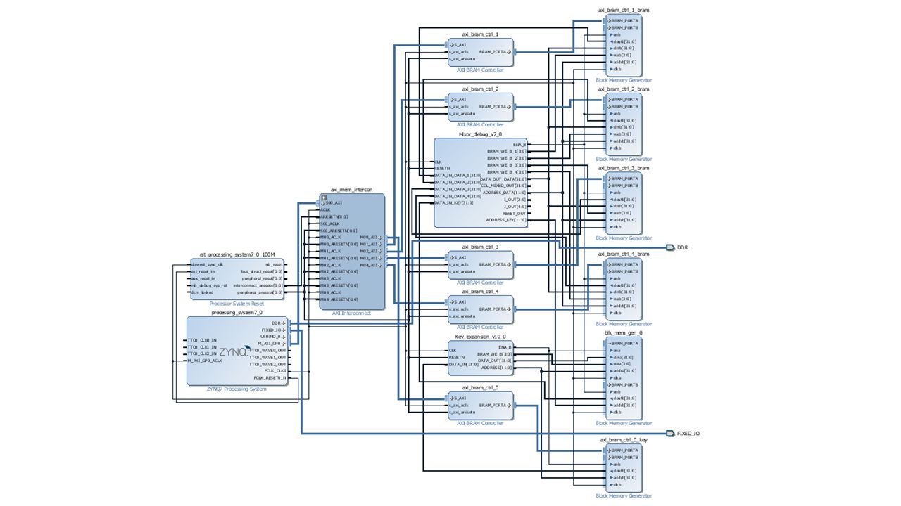
zedboard Integrated System Block Diagram DDR BRAM AXI4-bus BRAM AXI4-bus Key Expansion BRAM Mixor Mix Column Add Round Key ARM Processing System Programmable Logic UART

15
Handshake Synchronizing between ARM processor and hardware modules. Communication protocol via BRAM. Processor side: Processor writes data to BRAM. Processor rising the flag – designated address on BRAM. PL side: Waiting for flag – continuously reading from designated address. Executing. Initiating the flag. There is no need for synchronization in the opposite direction – hardware always completes its run before the processor needs the data. ARM PL Key Expansion BRAM Mixor Mix Column Add Round Key BRAM AXI4-bus BRAM AXI4-bus BRAM AXI4-bus BRAM AXI4-bus

16
Hardware Implementation Key Expansion The key expansion schedule gets the initial cipher key as its only argument, and outputs the extended key. It reads the cipher key from the BRAM, written there by the PS. The output is written to a different BRAM. The procedure is independent of the other functions, therefore it can operate as a background task, simultaneously to the rest of the code. Concurrency of ARM and FPGA was achieved by hardware implementation. ARM PL Key Expansion BRAM Mixor Mix Column Add Round Key BRAM AXI4-bus BRAM AXI4-bus Key Expansion BRAM

17
FINISH address_sig 0x0 BRAM_WE_B 1111 data_out_sig 0x0 Expand ena_key 1 SaveCol4 address_sig 0x1C InitFlag address_sig 0x0 BRAM_WE_B 1111 data_out_sig 0x0 flag = 0 flag = 1 RdCol4 address_sig 0x1C RdCol3 address_sig 0x18 RdCol2 address_sig 0x14 RdCol1 address_sig 0x10 idle address_sig 0x0 valid = 0 valid = 1 i < 43 Write2BRAM address_sig 0x20 + 4i data_out_sig key_out [1407-32i downto 1407-32(i+1)+1] BRAM_WE_B 1111 i := i +1 i = 43 Key Expansion state machine flow
![FINISH address_sig 0x0 BRAM_WE_B 1111 data_out_sig 0x0 Expand ena_key 1 SaveCol4 address_sig 0x1C InitFlag address_sig 0x0 BRAM_WE_B 1111 data_out_sig 0x0 flag = 0 flag = 1 RdCol4 address_sig 0x1C RdCol3 address_sig 0x18 RdCol2 address_sig 0x14 RdCol1 address_sig 0x10 idle address_sig 0x0 valid = 0 valid = 1 i < 43 Write2BRAM address_sig 0x20 + 4i data_out_sig key_out [ i downto (i+1)+1] BRAM_WE_B 1111 i := i +1 i = 43 Key Expansion state machine flow](http://images.slideplayer.com/27/9133932/slides/slide_17.jpg "FINISH address_sig 0x0 BRAM_WE_B 1111 data_out_sig 0x0 Expand ena_key 1 SaveCol4 address_sig 0x1C InitFlag address_sig 0x0 BRAM_WE_B 1111 data_out_sig 0x0 flag = 0 flag = 1 RdCol4 address_sig 0x1C RdCol3 address_sig 0x18 RdCol2 address_sig 0x14 RdCol1 address_sig 0x10 idle address_sig 0x0 valid = 0 valid = 1 i < 43 Write2BRAM address_sig 0x20 + 4i data_out_sig key_out [ i downto (i+1)+1] BRAM_WE_B 1111 i := i +1 i = 43 Key Expansion state machine flow")
18
Key Expansion ChipScope waveform Reading the cipher key from BRAM Expanding the key and writing to BRAM DATA_IN ADDRESS DATA_OUT DATA_IN ADDRESS DATA_OUT DATA_IN ADDRESS DATA_OUT

19
Hardware Implementation Mix Columns and Add Round Key Mixor is a combined module implements both Mix Columns and Add round Key. Both round key and state block are the module’s inputs. Reads the state block from a BRAM, shared with the PS. Reads the round key from a BRAM, written there by the Key Expansion module. The output is written to the shared BRAM, from which the PS reads the current block state. ARM PL Key Expansion BRAM Mixor Mix Column Add Round Key BRAM AXI4-bus BRAM AXI4-bus Mixor Mix Column Add Round Key BRAM

20
InitFlag ADDRESS_DATA 0x0 DATA_OUT_DATA 0x0 BRAM_WE_B_ {num_col} 1111 Mix ADDRESS_DATA 0x8 DATA_OUT_DATA ( col_mixed ) xor ( col_in_key ) BRAM_WE_B_ {num_col} 1111 SaveCol flag = 1 RdCol ADDRESS_DATA 0x4 ADDRESS_KEY 0x20 + 4x[ num_col + 4x( round + 1 ) ] flag= 0 idle ADDRESS_DATA 0x0 Mixor state machine flow
![InitFlag ADDRESS_DATA 0x0 DATA_OUT_DATA 0x0 BRAM_WE_B_ {num_col} 1111 Mix ADDRESS_DATA 0x8 DATA_OUT_DATA ( col_mixed ) xor ( col_in_key ) BRAM_WE_B_ {num_col} 1111 SaveCol flag = 1 RdCol ADDRESS_DATA 0x4 ADDRESS_KEY 0x20 + 4x[ num_col + 4x( round + 1 ) ] flag= 0 idle ADDRESS_DATA 0x0 Mixor state machine flow](http://images.slideplayer.com/27/9133932/slides/slide_20.jpg "InitFlag ADDRESS_DATA 0x0 DATA_OUT_DATA 0x0 BRAM_WE_B_ {num_col} 1111 Mix ADDRESS_DATA 0x8 DATA_OUT_DATA ( col_mixed ) xor ( col_in_key ) BRAM_WE_B_ {num_col} 1111 SaveCol flag = 1 RdCol ADDRESS_DATA 0x4 ADDRESS_KEY 0x20 + 4x[ num_col + 4x( round + 1 ) ] flag= 0 idle ADDRESS_DATA 0x0 Mixor state machine flow")
21
Mixor ChipScope waveform Mixor’s module execution over the 1 st column data_in_data1 bram_we_1 data_out_data data_in_key address_key col_mixed address_data

22
Hardware Blocks Implementation Performance Mixor HW implementation - 24 cycles = 0.24 µsec SW implementation - 2.545 µsec ~10 times faster Key Expansion HW implementation - 93 cycles = 0.93 µsec SW implementation - 15 µsec ~15 times faster

25
Encryption Time Split Software implementation Integrated system

26
Conclusions The hardware modules are much faster than the software functions. The data transmission’s overhead between PS and PL significantly decreases the system’s speed and causes to a sever slowdown in performance - 68% of running time. Main conclusion The integrated system is best suitable for executing intensive calculations, and low data traffic algorithms. The AES algorithm has high data traffic and therefore the hardware accelerator did not cause significant performance improvements.

27
Demonstration

Similar presentations


 Jen-Chang Liu, 2005 Adapted from lecture slides by Lawrie Brown.>")

 Simplified.>")
 ◦ Spatially distributed sensors to monitor physical or environmental conditions, and to cooperatively.>")


 Presented by: Venkata Marella Slide #9-1.>")


 Dr. Monther Aldwairi New York Institute of Technology- Amman Campus 10/18/2009 INCS 741: Cryptography 10/18/20091Dr.>")


