Download presentation
Presentation is loading. Please wait.

1
Lewis Theory of Bonding
Chemical Bonding Lewis Theory of Bonding

2
Types of bonding conditions between elements
Low Electronegativity and low Ionization energy (Metals) High electronegativity and High Ionization energy (Non-metals) Metallic bonding Ionic bonding (transferring of electrons between atoms) Ionic bonding Covalent bonding (sharing of electrons between atoms)
 High electronegativity and High Ionization energy (Non-metals) Metallic bonding. Ionic bonding (transferring of electrons between atoms) Ionic bonding. Covalent bonding (sharing of electrons between atoms)")
3
Electronegativity

4
Lewis Diagrams or Structures
A convention developed to “show” the relationship between atoms when they form bonds. Why is it necessary? predict where the electrons are in a molecule needed to predict the shape of a molecule

5
Lewis Diagrams for Ionic Compounds
Identify the number of valence shell electrons and determine the charge on the ion using the “stable octet rule”. Write the elemental symbol, place dots to represent the electrons in the valence shell, enclose in square brackets and write the ionic charge as a superscript. [Na]+ or [ Cl ]-

6
Lewis Diagrams for Covalent Compounds
Draw the Lewis Diagram for nitrogen trifluoride (NF3). Step 1. Count the valence electrons N = 5 F = ( 7) = 26 valence electrons
. Step 1. Count the valence electrons N = 5 F = ( 7) = 26 valence electrons")
7
Lewis Diagrams for Covalent Compounds
Step 2. Write a skeletal structure. Use the least electronegative atom in the centre Electronegativity: N = 3.0 & F = 4.0 F N = a pair of e- (a single bond)
")
8
Lewis Diagrams for Covalent Compounds
Step 3. Complete the octets for each terminal atom (except H) F N : ..
 F. N. : ..")
9
Lewis Diagrams for Covalent Compounds
Step 4. Assign any additional electrons as lone pairs on the central atom .. F N :

10
Lewis Diagrams for Covalent Compounds
Example 2. COCl2 (24 electrons) .. .. : : Cl C Cl .. .. : : O ..
 : : Cl. C. Cl : : O. ..")
11
Lewis Diagrams for Covalent Compounds
Step 5. Make multiple bonds where necessary to complete the octets. .. C Cl O : C Cl O : ..

12
Lewis Diagrams for Covalent Compounds
Example 3. Chlorate ion, ClO3- ((1 x 7) + (3 x 6) + 1) = 26 - .. .. .. : : O Cl O .. .. : : O ..
 + (3 x 6) + 1) = : : O. Cl. O : : O. ..")
13
Co-ordinate covalent bonds
In some covalent compounds, the bonds between atoms occur because one atom has donated both electrons to the covalent bond. This is called a coordinate covalent bond. N H + N : H H+ + Nitrogen supplies the two lone pair electrons to this N-H bond. The H+ ion has no electrons.

14
Co-ordinate covalent bonds
To determine the number of coordinate covalent bonds – subtract the bonding capacity (lone valence electrons) from the number of bonds the atom has. N H + Nitrogen Bonds 4 Bonding capacity 3 Coordinate bonds 4-3=1
 from the number of bonds the atom has. N. H. + Nitrogen Bonds 4 Bonding capacity 3 Coordinate bonds 4-3=1.")
15
In some compounds the SCH3U guidelines may not “work”.
On occasion, both elements have the same electronegativity or there may be two or more possible Lewis Structures. e.g. CS2 (both electronegativities = 2.5) is it S=C=S or C=S=S ?
 is it S=C=S or C=S=S")
16
Formal Charge In such situations, one determines the Formal Charge. The option with the lowest formal charge has the most stable and viable structure. The Formal Charge for an atom is the number of valence electrons in the free neutral atom minus the number of valence electrons assigned to the atom in the Lewis structure.

17
Formal Charge Formal Charge = (# valence electrons)-(# of bonds)-(# of unshared e-)
-(# of bonds)-(# of unshared e-)")
18
C=S=S : .. C S S Valence electrons Electrons assigned Formal Charge

19
S=C=S .. : S C S Valence electrons Electrons assigned Formal Charge 0 0 0

20
Resonance Structures In some structures the Lewis structure does not represent the true structure of the compound. Bond order is the number of shared pairs of electrons between two atoms. (i.e. – the number of bonds between two atoms) As the bond order increases. . . The length of the bond decreases. The energy associated with breaking the bond increases.
 As the bond order increases. . . The length of the bond decreases. The energy associated with breaking the bond increases.")
21
Bond order The number of shared electrons in a bond affects its length and energy. Bond Type Bond Order Bond Length (pm) (10-12m) Bond Energy (kJ/mol) C-O 1 143 351 C=O 2 121 745 C-C 154 348 C=C 134 615 C C 3 120 812 C-N 276 C=N 138 C N 116 891
 (10-12m) Bond Energy (kJ/mol) C-O C=O C-C C=C C C C-N C=N C N")
22
Resonance structure C H O -1 CHO2- is a polyatomic ion with the following Lewis structure. The C-O bond lengths are experimentally determined to be between C-O and C=O. The bond order is neither 1 or 2, but considered to be somewhere in between (i.e.-1.5). The Lewis structure does not support the experimental data.
. The Lewis structure does not support the experimental data.")
23
Resonance structure The actual structure is a resonance hybrid of the two resonance structures. C H O -1 The resonance structure does not “flip-flop” back and forth between the two. It is a hybrid form of the two.

24
Resonance structure The bond order for NO3- is, (1+1+2)/3=1.33.
The resonance structure is N O -1

25
Benzene has a bond order of 1.5. (1+2+1+2+1+2)/6=1.5
C H C H

26
Nature of the chemical bond
The work on quantum theory in conjunction with the success of Lewis structures resulted in the inevitable connections between the two areas of study. Linus Pauling , a friend of Gilbert Lewis, connected the two with the valence bond theory.

27
Valence Bond Theory The half filled orbital of one atom overlaps a half filled orbital of a second atom to form a full orbital with two electrons spinning in opposite directions. The bonding atoms arrange themselves in order to maximize the overlap of the half-filled orbitals. Maximum overlapping of the orbitals creates a bonding orbital with a lower energy and increased stability.

28
Valence Bond Theory The combination of electrostatic repulsion and opposing magnetic fields (due to the electron’s spin) creates the stability associated with a bonding orbital. Electron Spin Negative charge Electrostatic repulsion Negative charge Electron Spin “North” magnetic field Magnetic attraction “South” magnetic field
 creates the stability associated with a bonding orbital. Electron Spin. Negative charge. Electrostatic repulsion. Negative charge. Electron Spin. North magnetic field. Magnetic attraction. South magnetic field.")
29
Valence Bond Theory During this process, two atoms approach each other and allow their half filled orbitals to overlap and form the stability of a filled bonding orbital.

30
Hybrid Orbitals In some situations a more advantageous bonding scenario can be established by promoting electrons from a full orbital to a similar empty orbital to create two half filled orbitals that are available for bonding. The resulting orbital is a mixture of the two original orbitals and is called a hybrid orbital.

31
Hybrid Orbitals Electrons are promoted from the full “s-orbital” into an empty “p-orbital” which results in hybrid orbitals that have one electron per orbital and characteristics unique to the newly formed orbitals. The new hybrid orbitals are free to become involved in bonds by overlapping with other half filled valence orbitals.

32
Hybridization C (z = 6) C (z = 6) C (z = 6) C (z = 6) C (z = 6)
1s 2s 2p C (z = 6) 1s sp3 C (z = 6) sp3 hybridization 1s 2s 2p C (z = 6) 1s sp2 C (z = 6) sp2 hybridization p 1s 2s 2p C (z = 6) 1s sp C (z = 6) sp hybridization p 1s 2s 2p C (z = 6)
 1s. sp3. C (z = 6) sp3 hybridization. 1s. 2s. 2p. C (z = 6) 1s. sp2. C (z = 6) sp2 hybridization. p. 1s. 2s. 2p. C (z = 6) 1s. sp. C (z = 6) sp hybridization. p. 1s. 2s. 2p. C (z = 6)")
33
sp2 Hybrid atomic orbitals

34
sp3 Hybrid atomic orbitals

35
Double & Triple Bonds Sigma (s) bonds – The “end-to-end” overlapping of half filled orbitals to make a full bonding orbital of lower energy level (i.e. – more stable) They occur between “s”, “p” and hybrid orbitals (“sp”,“sp2” & “sp3”) to make single covalent bonds.
 bonds – The end-to-end overlapping of half filled orbitals to make a full bonding orbital of lower energy level (i.e. – more stable) They occur between s , p and hybrid orbitals ( sp , sp2 & sp3 ) to make single covalent bonds.")
36
Double & Triple Bonds Pi (p) bonds – The “side-to-side” overlapping of half filled “p” orbitals to make more stable filled bonding orbitals.
 bonds – The side-to-side overlapping of half filled p orbitals to make more stable filled bonding orbitals.")
37
Double & Triple Bonds A combination of “p” and “s” bonds makes double and triple bonds. Single bonds Sigma only (s) Double bonds 1 Sigma (s) and 1 Pi (p)
 and 1 Pi (p)")
38
Triple bonds 1 Sigma (s) and 2 Pi (p)
Double & Triple Bonds A combination of “p” and “s” bonds makes double and triple bonds. Sigma (s ) bond Pi (p ) bond Pi (p ) bond Triple bonds 1 Sigma (s) and 2 Pi (p)
 bond. Pi (p ) bond. Pi (p ) bond. Triple bonds 1 Sigma (s) and 2 Pi (p)")
39
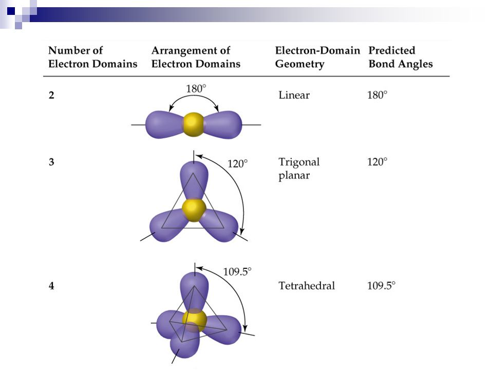
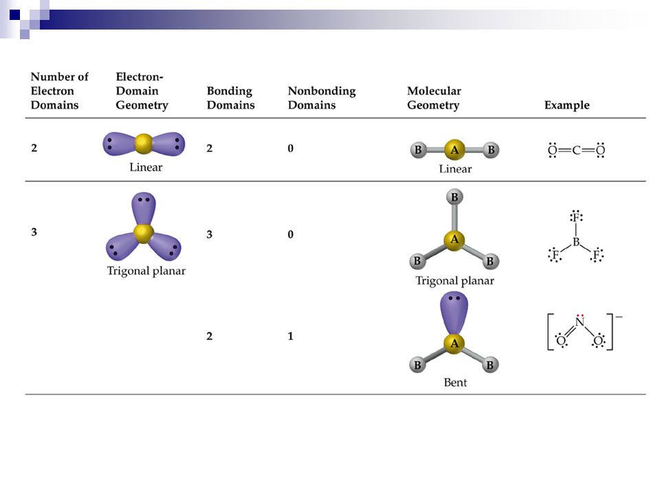
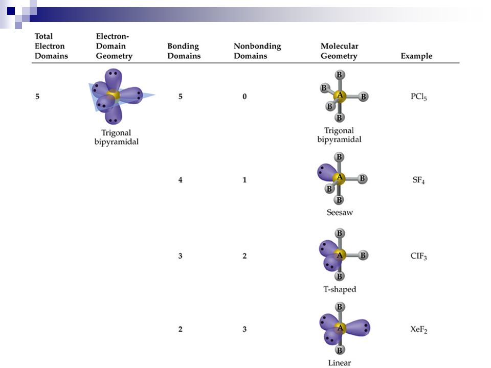
Molecular shapes Valence shell electron pair repulsion (VSEPR) theory
Only valence shell electrons of the central atom are important in the molecular shape. Valence shell electrons will repel to maximize the distance between the pairs Bond pairs and lone pairs behave similarly

40
Molecular shapes

47
e-pairs Notation Name of VSEPR shape Examples 2 AX2 Linear
HgCl2 , ZnI2 , CS2 , CO2 3 AX3 Trigonal planar BF3 , GaI3 AX2E Non-linear (Bent) SO2 , SnCl2 4 AX4 Tetrahedral CCl4 , CH4 , BF4- AX3E (Trigonal) Pyramidal NH3 , OH3- AX2E2 Non-Linear (Bent) H2O , SeCl2 5 AX5 Trigonal bipyramidal PCl5 , PF5 AX4E Distorted tetrahedral (see-sawed) TeCl4 , SF4 AX3E2 T-Shaped ClF3 , BrF3 AX2E3 I3- , ICl2- 6 AX6 Octahedral SF6 , PF6- AX5E Square Pyramidal IF5 , BrF5 AX4E2 Square Planar ICl4- , BrF4-
 SO2 , SnCl2. 4. AX4. Tetrahedral. CCl4 , CH4 , BF4- AX3E. (Trigonal) Pyramidal. NH3 , OH3- AX2E2. Non-Linear (Bent) H2O , SeCl2. 5. AX5. Trigonal bipyramidal. PCl5 , PF5. AX4E. Distorted tetrahedral. (see-sawed) TeCl4 , SF4. AX3E2. T-Shaped. ClF3 , BrF3. AX2E3. I3- , ICl2- 6. AX6. Octahedral. SF6 , PF6- AX5E. Square Pyramidal. IF5 , BrF5. AX4E2. Square Planar. ICl4- , BrF4-")
Similar presentations