Download presentation
Presentation is loading. Please wait.

1
Flying The WAAS GPS Presented by John D
Flying The WAAS GPS Presented by John D. Collins June 13, 2014 Branson Mo Twin Cessna Flyers

2
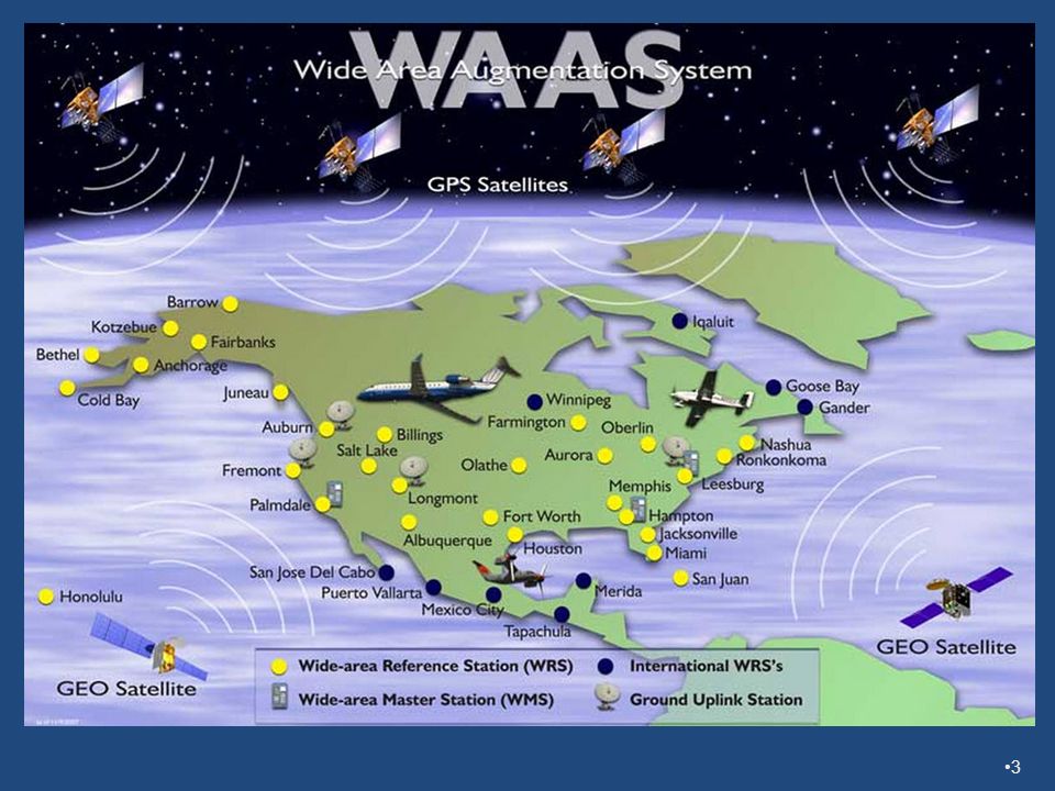
WAAS Overview What is WAAS? It stands for Wide Area Augmentation System Provides improved Position Accuracy including Horizontal to 2 meters (localizer equivalent) Vertical to 3 meters (allows vertical guidance) It also provides enhanced system integrity Replaces RAIM
 Vertical to 3 meters (allows vertical guidance) It also provides enhanced system integrity. Replaces RAIM.")
5
RNAV (GPS) Approaches More Common
As of May 1, 2014 there are almost three times the number of RNAV approaches with LPV minimums than ILS Category 1 approaches 3,404 LPV Verses 1,269 ILS Approaches There are 13,957 approaches that use space based GPS and 6,439 approaches that use ground based facilities

6
What is a WAAS Approach? There are two types LPV – Localizer Performance with Vertical (DA) LP – Localizer Performance (MDA)
 LP – Localizer Performance (MDA) .")
7
A WAAS GPS can also fly these non WAAS Approaches
LNAV/VNAV (DA) using WAAS for the vertical LNAV (MDA) The WAAS GPS can also provide advisory vertical guidance with the following approach annunciations: LNAV+V (to an MDA) LP+V (to an MDA)
 using WAAS for the vertical. LNAV (MDA) The WAAS GPS can also provide advisory vertical guidance with the following approach annunciations: LNAV+V (to an MDA) LP+V (to an MDA)")
8
Typical WAAS Coverage This is a daily plot of the coverage of LPV 200 quality signal. Most of the country is covered 100 percent of the time with the West Coast often having coverage down to 94 percent. When satellites fail, the coverage suffers accordingly. See 8

9
A Solar Storm Good chunks of the northeast and mid west loose vertical LPV capability during the storm 9

10
But LNAV Still Available at 100%
Even so, LNAV is still 100 percent available 10

11
Entire WAAS System was down on Friday 10/21/11 for 4 hours caused by an error during a software upgrade Hello John, There was a true WAAS system outage Friday 10/21/11. The WAAS operators were performing a software upgrade to the system and the system unexpectedly came down for approximately 4 hours. This a very rare event and should not happen again. Steps are being taken this week to ensure what caused the problem never happens again. The upgrade procedures are being updated to include checks against the oversight. 11

12
WAAS Integrity Integrity – the function that alerts the pilot if the Navigational Information cannot be relied on HPL - Horizontal Protection Level – % probability that the horizontal position is contained within the limits VPL - Vertical Protection Level – % probability that the vertical position is contained within the limits 12

13
HAL – Horizontal Alarm Limit is the highest value of HPL that is permitted for a given type of approach For an LNAV or LNAV/VNAV approach, this value is 556 meters For an LP or LPV approach, this value is 40 meters

14
Vertical Alarm Limit VAL – Vertical Alarm Limit is the highest value of VPL that is permitted for a given type of approach with vertical guidance For an LPV approach with a DH 250 feet or higher, this value is 50 meters For an LPV approach with a DH below 250 feet to 200 feet, this value is 35 meters

15
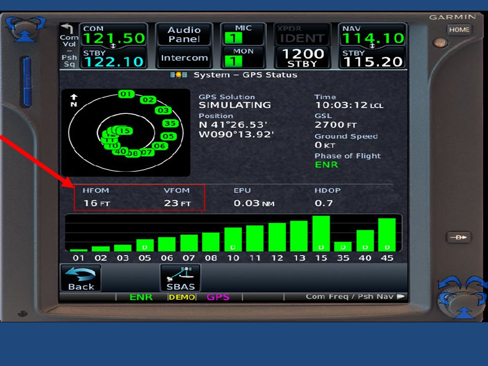
On the GNS430W/530W, GTN series or G1000 how do you know if the current signal is likely to be adequate to fly a planned LPV or other approach with vertical guidance? The GNS430W/530W, GTN series, and G1000 display the following two related values: HFOM - Horizontal Figure of Merit – the 95% probability of maximum horizontal error in feet VFOM - Vertical Figure of Merit – the 95% probability of maximum vertical error in feet

16
TIP When the VFOM is less than 40 feet, vertical guidance is available on all approaches including those with a 200 foot DH When the VFOM is less than 60 feet, vertical guidance is available on any approach with LNAV+V, LP+V, L/VNAV, and an LPV as long as the DH is 250 feet or greater Typical values in this area are a VFOM at 20 feet. 16

17
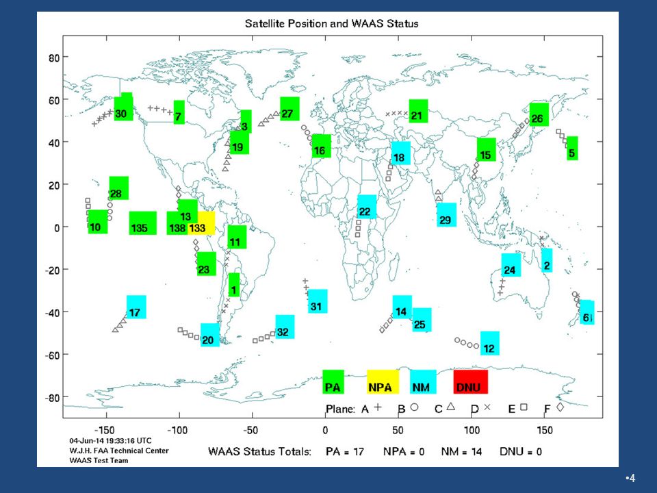
GNS530W HFOM and VFOM, satellites above 32 are geo, subtract 78 from prn, so current geos are 48 and 51 17

18
Tip: How do you know if an LNAV will have +V ?
I get several questions such as how do I determine if the approach will have advisory vertical guidance? 18

19
CDI Scaling for a WAAS GPS is angular and not Fixed as it is with a non WAAS GPS

20
LNAV CDI Scaling is angular
Main difference between LNAV using full procedure and VTF is +/- 2 degrees to point where it is fixed at +/- 1 NM. 20

21
LNAV VTF Scaling LNAV with VTF, major difference is that it is angular until +/- 1 NM FSD. 21

22
GP fixed last .4 to .5 NM to threshold for LPV, 1.7 NM for LNAV/VNAV
Full scale for a 3 degree glideslope and a TCH of 40 ft. GPIP is 763 feet beyond the threshold. The full scale deflection is +/ (500) feet when beyond 36,830 feet or 6.1 NM from the threshold, then angular at +/- .75 degrees full scale until LNAV/VNAV is 1.7 NM from threshold, full scale remains fixed at +/ (150) feet and LPV is .5 NM from the threshold, full scale remains fixed at +/ (50) feet. An ILS comparison is +/- .7 degrees out to the end of the service volume 10 to 20 NM. GP fixed last .4 to .5 NM to threshold for LPV, 1.7 NM for LNAV/VNAV GP fixed beyond 6 NM +/- 492 feet FSD 22
 feet when beyond 36,830 feet or 6.1 NM from the threshold, then angular at +/- .75 degrees full scale until LNAV/VNAV is 1.7 NM from threshold, full scale remains fixed at +/ (150) feet and LPV is .5 NM from the threshold, full scale remains fixed at +/ (50) feet. An ILS comparison is +/- .7 degrees out to the end of the service volume 10 to 20 NM. GP fixed last .4 to .5 NM to threshold for LPV, 1.7 NM for LNAV/VNAV. GP fixed beyond 6 NM +/- 492 feet FSD. 22.")
23
TIP - Flying an Approach with an out of date database
AFMS must permit GPS approaches with an out of date Database (GNS430W/530W and GNS480 AFMS permit this) The pilot must verify that the effective date of the approach procedure is not after the effective date of the expired database. Reference AIM section , table 1-1-6, note 3 for IFR Approach It reads: “Requires current database or verification that the procedure has not been amended since the expiration of the database.” 23
 The pilot must verify that the effective date of the approach procedure is not after the effective date of the expired database. Reference AIM section , table 1-1-6, note 3 for IFR Approach. It reads: Requires current database or verification that the procedure has not been amended since the expiration of the database. 23.")
24
AeroNav and Jeppesen added a new date that only changes if the change affects the database called the procedure amendment date. On the AeroNav charts this replaces the old Julian chart date in the lower left hand corner and is in human form. The old Julian date is moved to the upper right hand corner. As long as the expired database effective date is after the date in the lower left hand corner, the approach data in the expired database can be used 24

25
Jeppesen put the new date on the left hand edge of the chart near the minimums. They also explain the reason for the change. 25

26
WAAS GPS filing an alternate
An airport with a RNAV (GPS) approach may be chosen as an alternate if the approach is designated as authorized to be used as an alternate. For planning purposes, the weather must be based on LNAV alternate minimums and is normally 800-2 For approaches which require the use of an ADF or DME and the WAAS GPS needs to be used in lieu of the ADF or a DME, the approach may be used for the purposes of filing an alternate. If a Terminal Forecast (FA) is unavailable at the alternate airport, the area forecast (FA) and the AIRMET Sierra must be used to determine the forecast weather. This effectively requires VFR conditions. Does not use RAIM for integrity and therefore doesn’t need a RAIM check before flight or prior to an approach TAF is only valid within a 5 mile radius from the center of the airport. An area forecast (FA) is a forecast of Visual Flight Rules (VFR) clouds and weather conditions over an area as large as the size of several states. It must be used in conjunction with the AIRMET Sierra (IFR) bulletin for the same area in order to get a complete picture of the weather. The FA consists of a: 12 hour forecast plus a 6 hour outlook. All times are Coordinated Universal Time (UTC). All distances except visibility are in nautical miles. Visibility is in statute miles. synopsis section which is a brief summary of the location and movement of fronts, pressure system, and circulation patterns for an 18 hour period. VFR clouds and weather section which is a 12 hour forecast, in broad terms, of clouds and weather significant to flight operations plus a 6 hour categorical outlook. This section is usually several paragraphs. AIRMET Sierra supplies information regarding Instrument Flight Rule (IFR) conditions. The breakdown may be by states, by well known geographical areas, or in reference to location and movement of a pressure system or front. A categorical outlook, identified by OTLK, is included for each area breakdown. AIRMET Sierra is issued for: Instrument Flight Rules (IFR) or Mountain Obscuration - Ceilings less than 1000 feet and/or visibility less than 3 miles affecting over 50% of the area at one time. WAUS42 KKCI MIAS WA AIRMET SIERRA UPDT 1 FOR IFR VALID UNTIL CSTL WTRS WA-NRN HLF OR...SCT060 BKN-OVC100. TOPS FL250. ISOL -SHRA. 21Z SCT100..BKN CI. OTLK...VFR. SRN HLF OR...SCT015 SCT-BKN100. TOPS 150. OTLK...VFR. NRN CA...SCT Z OFFSHORE BKN010. TOPS 020. OTLK...OFFSHORE MVFR CIG...NRSHORE VFR. CNTRL CA...SKC. OTLK...VFR. SRN CA...BKN010. TOPS 020. OTLK...IFR CIG. .... AIRMET IFR...NC SC FROM 20N GSO TO 30NE RDU TO 40WSW ILM TO 30SSE CAE TO SPA TO 20N GSO CIG BLW 010/VIS BLW 3SM BR. CONDS ENDG 12-15Z. 26
 approach may be chosen as an alternate if the approach is designated as authorized to be used as an alternate. For planning purposes, the weather must be based on LNAV alternate minimums and is normally For approaches which require the use of an ADF or DME and the WAAS GPS needs to be used in lieu of the ADF or a DME, the approach may be used for the purposes of filing an alternate. If a Terminal Forecast (FA) is unavailable at the alternate airport, the area forecast (FA) and the AIRMET Sierra must be used to determine the forecast weather. This effectively requires VFR conditions. Does not use RAIM for integrity and therefore doesn’t need a RAIM check before flight or prior to an approach. TAF is only valid within a 5 mile radius from the center of the airport. An area forecast (FA) is a forecast of Visual Flight Rules (VFR) clouds and weather conditions over an area as large as the size of several states. It must be used in conjunction with the AIRMET Sierra (IFR) bulletin for the same area in order to get a complete picture of the weather. The FA consists of a: 12 hour forecast plus a 6 hour outlook. All times are Coordinated Universal Time (UTC). All distances except visibility are in nautical miles. Visibility is in statute miles. synopsis section which is a brief summary of the location and movement of fronts, pressure system, and circulation patterns for an 18 hour period. VFR clouds and weather section which is a 12 hour forecast, in broad terms, of clouds and weather significant to flight operations plus a 6 hour categorical outlook. This section is usually several paragraphs. AIRMET Sierra supplies information regarding Instrument Flight Rule (IFR) conditions. The breakdown may be by states, by well known geographical areas, or in reference to location and movement of a pressure system or front. A categorical outlook, identified by OTLK, is included for each area breakdown. AIRMET Sierra is issued for: Instrument Flight Rules (IFR) or Mountain Obscuration - Ceilings less than 1000 feet and/or visibility less than 3 miles affecting over 50% of the area at one time. WAUS42 KKCI MIAS WA AIRMET SIERRA UPDT 1 FOR IFR VALID UNTIL CSTL WTRS WA-NRN HLF OR...SCT060 BKN-OVC100. TOPS FL250. ISOL -SHRA. 21Z SCT100..BKN CI. OTLK...VFR. SRN HLF OR...SCT015 SCT-BKN100. TOPS 150. OTLK...VFR. NRN CA...SCT Z OFFSHORE BKN010. TOPS 020. OTLK...OFFSHORE MVFR CIG...NRSHORE VFR. CNTRL CA...SKC. OTLK...VFR. SRN CA...BKN010. TOPS 020. OTLK...IFR CIG AIRMET IFR...NC SC FROM 20N GSO TO 30NE RDU TO 40WSW ILM TO 30SSE CAE TO SPA TO 20N GSO CIG BLW 010/VIS BLW 3SM BR. CONDS ENDG 12-15Z. 26.")
27
Alternate information using AeroNav Charts
A WAAS GPS can use a RNAV (GPS) approach as an alternate if: The AeroNav chart does not have NA, indicating the approach is not authorized as an alternate. If there is a symbol but without the NA, then non-standard alternate minimums apply and details are found in section M. If there is no symbol, then standard alternate minimums apply A A 27
 approach as an alternate if: The AeroNav chart does not have NA, indicating the approach is not authorized as an alternate. If there is a symbol but without the NA, then non-standard alternate minimums apply and details are found in section M. If there is no symbol, then standard alternate minimums apply. A. A. 27.")
28
Jeppesen Alternate Information
The Jeppesen Airport Chart notes indicate if and what minimums are required.

29
When would you use a WAAS GPS to fly the LNAV/VNAV DA?
Not often, for the most part this minima can be ignored On the vast majority of RNAV (GPS) approaches, if there is a LNAV/VNAV DA, there will be a lower LPV DA When there is a LPV DA charted, the GPS will not offer the LNAV/VNAV All downgrades are to LNAV without vertical guidance, there are no downgrades to LNAV/VNAV The LNAV/VNAV minimums are primarily intended for aircraft with a Baro VNAV system, not normally found in piston GA aircraft
 approaches, if there is a LNAV/VNAV DA, there will be a lower LPV DA. When there is a LPV DA charted, the GPS will not offer the LNAV/VNAV. All downgrades are to LNAV without vertical guidance, there are no downgrades to LNAV/VNAV. The LNAV/VNAV minimums are primarily intended for aircraft with a Baro VNAV system, not normally found in piston GA aircraft.")
30
RNAV Typical Minimum Relationship
The LPV has the lowest, then the LNAV/VNAV, and finally the LNAV. 30

31
LNAV/VNAV Lower than LPV

32
LNAV Lower than LPV or LNAV/VNAV

33
LNAV/VNAV How DA is affected by Obstacles
D can be over 4000 feet. These show where the DA would be established if there are obstacles that penetrate the OCS (Obstacle Clearance Surface) 33
 33.")
34
Affect of Obstacles on LPV DA
If an obstacle penetrates the OCS close to the runway, the DA is moved back and up so that when you break out the obstacle is in the visual segment so you can see and avoid it. 34

35
LP Approaches Analogous to a Localizer only approach
Advisory vertical guidance only available on GNS430W/530W at Software Version 5.10 or later (LP+V) Will always be charted with LNAV minimums, never with an LPV or LNAV/VNAV Downgrade to LNAV if HPL exceeds 40 meters FAA plans to publish either LP or LPV at each runway LP will only be published if MDA is at least 20 ft lower than LNAV 539 LP procedures are now published MUST have an annunciation of LP in order to use the minimums, LNAV annunciation is not permitted to fly these minimums
 Will always be charted with LNAV minimums, never with an LPV or LNAV/VNAV. Downgrade to LNAV if HPL exceeds 40 meters. FAA plans to publish either LP or LPV at each runway. LP will only be published if MDA is at least 20 ft lower than LNAV. 539 LP procedures are now published. MUST have an annunciation of LP in order to use the minimums, LNAV annunciation is not permitted to fly these minimums.")
36
LP with big improvement in MDA
A 500 foot MDA improvement for the LP over the LNAV. 36

37
Advisory Vertical Guidance
Only available on approaches that: LNAV minimums are highest service the approach is straight in to a runway Never available when a LPV, LNAV/VNAV, or LP is downgraded Treating the MDA as a DA is not authorized, no sink thru allowed Must observe minimum, maximum, and required altitudes Level off at MDA to provide time to locate runway environment Baro Altitude is affected by temperature Altimeter will read lower than actual with Hot temperatures Altimeter will read higher than actual with cold temperatures Glidepath is relatively fixed in space and independent of temperature Error increases with altitude above Baro setting site No protection below the MDA from obstacles

38
LNAV that will have Advisory Vertical Guidance LNAV+V
38

39
Vertical guidance will not always clear
step downs beyond FAF On a 35C degree (95F) day, following the glidepath, the altimeter will indicate 229 feet lower than the 4000 foot minimum, 300 feet lower than the 5000 foot minimum, 372 feet lower than the 6000 foot minimum, and 444 feet lower than the 7000 foot minimum. VTF will have the GP from a point 30 NM from NLSON. If you receive the clearance, “cleared direct WELET, maintain 7000 to WELET, cleared RNAV Y RWY 36L approach, and the temperature at Charlotte is 95F, if you follow the GP, you will likely get a PD. 39
 day, following the glidepath, the altimeter will indicate 229 feet lower than the 4000 foot minimum, 300 feet lower than the 5000 foot minimum, 372 feet lower than the 6000 foot minimum, and 444 feet lower than the 7000 foot minimum. VTF will have the GP from a point 30 NM from NLSON. If you receive the clearance, cleared direct WELET, maintain 7000 to WELET, cleared RNAV Y RWY 36L approach, and the temperature at Charlotte is 95F, if you follow the GP, you will likely get a PD. 39.")
40
Dangers of using Advisory Vertical Guidance below MDA
Absolutely no guarantee of obstacle clearance LP and LNAV Approaches were designed for Dive and Drive, not using a single angle all the way to the threshold FAA now removing Visual Descent Angle and TCH from LNAV and LP approach charts when the visual segment has obstacle penetrations in the 20 to 1 slope. They also now add a note, “Descent Angle NA” to affected charts and notes such as “Approach NA at Night”. It will take some time before all charts are updated

41
Jeff Van West wrote an article in the Oct 2011 issue of IFR regarding the hazard of using the advisory glidepath below the MDA. 41

42
A dangerous example, RNAV 7 at N23 + V takes you below the ridge line
Jeff Van West wrote about this in IFR. Note that the runway which is behind the ridge, shows thru the ridge with SVT. Also note that this is well below the MDA. Following the advisory glidepath above the MDA is safe, but don’t follow it below the MDA. 42

44
Analyzing the approach Chart Information regarding the visual segment

45
Visual Segment Clear on 34 to 1
If the gray feather symbol is shown on the chart, the visual segment is supposed to be clear on a 34 to 1 slope. 45

46
Visual Segment Clear on 20 to 1
In order for a VDP to be published, the visual segment has to be clear on a 20 to 1 slope. As a reference, a 3 degree glidepath is 19 to 1. 46

47
Visual segment not clear on 20 to 1

48
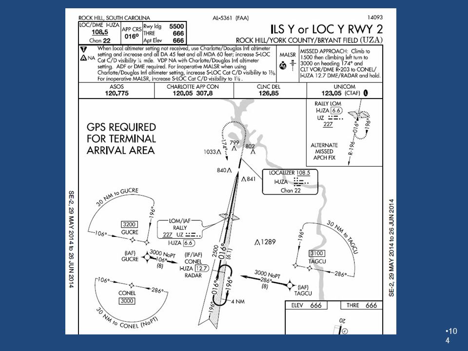
Flying the TAA

49
The Terminal Arrival Area
Pilots entering the TAA and cleared for an approach by air traffic control, are expected to proceed directly to the IAF associated with that area of the TAA at the altitude depicted, unless otherwise cleared by air traffic control. A TAA segment is considered as a feeder route and a depicted part of the approach. Unlike an MSA, when cleared for the approach, you may descend to the segment altitude. Tip: Make sure that the center fix bearing is used to determine TAA IAF to use. 49

50
Last assigned altitude, 6000 MSL. You receive the following clearance:
“Twin Cessna, 12345, 20 miles north of UUKAY, cleared direct UUKAY, Cleared RNAY RWY 4 Approach, Lexington” When may you descend and to what altitude? Assume the pilot is level at 6000 feet and 20 NM east of SAAPP intersection and receives the following clearance: Bonanza 1234A is cleared direct FRNZI, cleared RNAV RWY 4 approach Lexington. When can the pilot start down? Similar clearance, Bonanza 1234A cleared direct to FRNZI. If the aircraft is 35 NM east of SAAPP? Same approach clearance, but with maintain 6000 until entering the TAA. What is the altitude rule for lost communication? 50

51
What does Fly Visual Mean?

52
52

53
Fly Visual to Airport Provides relief from FAR requirements for leaving the DA Missed approach climb terrain protection of 200 ft/NM is only provided at the MAP at the DA altitude. The flight visibility requirement in the approach must be met to leave the DA or an immediate missed approach is expected. This is a visual procedure, meaning that terrain clearance and flight to the runway must be accomplished by visual means. You must remain clear of any clouds. Descent below the DA is authorized as long as the required flight visibility is available. There is no requirement that the DA be treated as if it were an MDA until the runway is in sight. The GP may be used as long as the aircraft continuously meets the visual requirements. Tip: the pilot be positive that a landing can be accomplished by visual means from the MAP DA, as a missed approach from a point beyond the MAP DA means the pilot must provide for their own terrain avoidance. 53

54
Joining the Approach

55
When is flying the hold in lieu of a PT required?
Answer: If it is charted, it is required, unless:

56
The Hold is not permitted when:
Cleared “Straight In” for the approach When on radar vectors to final On any feeder route, segment, or TAA sector that has NoPt depicted When in the hold and cleared for the approach

57
TIP: If in doubt, clarify the situation with the controller (91.123)
The HILPT is a “once around” procedure where the holding waypoint is crossed twice, once on entry to the hold and once inbound to the FAF. Any circuits of the HILPT to lose altitude, etc. in addition to the “once around” or when the hold is not indicated, the pilot must obtain a clearance to fly the hold

58
TEST – IS a HOLD required?
Yes, the HILPT is required, unless the controller clears the aircraft “straight-in”. In most circumstances, I would expect a straight-in clearance and many controllers assume straight-in and don’t realize the pilot is required by regulation under these circumstances to fly the hold. To avoid confusion, if not cleared straight-in, confirm with the controller that they want you to fly the hold requires the pilot to clarify any clearance that is not clear.

59
Why do I sometimes get asked to fly a hold and other times I don’t?
Answer – it depends on where you are arriving at the hold fix

60
Adding the approach west of CORON, the hold may or may not be required, so the GTN asks.
60

61
Controlling the Hold In-Lieu of A procedure Turn
When the hold is the active leg annunciated by the GPS: When the GPS displays SUSP then the guidance will remain in the hold When the GPS is not displaying SUSP, then the guidance will be to sequence to the next waypoint on the approach Pressing OBS will toggle SUSP on and off.

62
Cleared direct UPBID, GPS RWY 23 Approach, It is not an available Choice
Note center IF, UPBID is not an IAF. Would have to load the full procedure from one of the IAF’s and then scroll thru the flightplan to UPBID and then press the Direct-To, Enter, Enter to navigate to UPBID. 62

63
ATC Rules for Clearance to an IF or step down fix to start an approach
Aircraft must have filed as advanced RNAV (/G) Altitude assigned until on a published segment of the approach Radar monitoring required until established Direct to IF only permitted is angle to final approach 90 degrees or less and 30 degrees or less for a step down fix. Must advise pilot to expect clearance direct to the fix by at least 5 NM 63
 Altitude assigned until on a published segment of the approach. Radar monitoring required until established. Direct to IF only permitted is angle to final approach 90 degrees or less and 30 degrees or less for a step down fix. Must advise pilot to expect clearance direct to the fix by at least 5 NM. 63.")
64
Where does the glidepath come on
VTF – 31 NM before the FAF when the aircraft is generally aligned with the final approach path Full procedure – when the FAF is the active waypoint for the current Leg Note: sometimes this is a short leg, leaving the autopilot Insufficient time to capture the glidepath

65
This approach will cause the CIII fits as the glidepath doesn’t come on until DEFOX and you have to lose 500 feet in 1.6 NM and get the autopilot to capture the glidepath. 65

66
The Miss 66

67
Don’t be in a hurry to get missed approach navigational guidance
Fly the miss, power up, pitch up, positive rate, Gear up You can wait until you have completed the initial Climb and started any required initial turn Verify that SUSP is annunciated, only then press OBS

68
TIP: Don’t be in a hurry to press OBS, wait until you see SUSP annunciated
Don’t be in a hurry to press OBS to navigate the Missed approach procedure. At the MAP, start your climb and initial turn if required, then verify that SUSP is annunciated, then press OBS. 68

69
Here is what happens if you press OBS with out first
getting SUSP. Don’t press OBS until after the SUSP happens at the MAP. If you do, you will transition to OBS mode, return to TERM sensitivity and not cycle at the MAP to the MAP procedure. To repair this, activate the leg from the MAP to the first MAP procedure fix. 69

70
TIP If you mess up and press the OBS before SUSP, the GNS400W/500W series will go into OBS mode To undo this, use Direct-to, Direct-to, and enter, to reactivate the leg to final. Then when SUSP comes on, you can press OBS

71
Questions ?

72
Supplemental Charts

73
Hidden in plain view

74
Hidden in plain view

75
Hidden in plain view

76
Hidden in plain view

77
Hidden in plain view

78
+Map

79
+Map

80
+Map

81
+Map

82
Parallel Track

83
Parallel Track

84
Parallel Track

85
Parallel Track

86
Full RNAV approach with GPSS
With GPSS engaged (usually Heading mode on AP) fly procedure until aligned with final, then engage the approach mode
 fly procedure until aligned with final, then engage the approach mode.")
87
Full RNAV Approach Without GPSS
Use Heading or Nav mode to navigate to IAF or IF. Use Heading mode to fly procedure until aligned with final, then engage the approach mode

88
Lateral Guidance System
Command Console Lateral Guidance System For GPSS operation, select GPSS on the GPSS switch. Select HDG on the Century III Command Console and HDG on the Lateral Guidance System. To intercept the GS, select ALT on the Command Console and LOC NORM on the Lateral Guidance System. Must have a half scale fly up and centered CDI for 10 to 20 seconds in order for GS to be captured. If GS is captured, a separate GS green light will light. 88

89
For GPSS operation, select GPS on the GPSS switch
For GPSS operation, select GPS on the GPSS switch. Select HDG on the Century 2000 or Century 41 Command Console. To intercept the GS, select ALT and APR on the Command Console. If being vectored to final and connected to an HSI, press both HDG and APR simultaneously. Intercept can occur from above or below in ALT or ATT mode. Intercepting from below is best, but you can force GS capture by flying thru the center of the GS in ATT or ALT mode. When the conditions are met for capturing a GS, the GS annunciator will come on along with ATT and or ALT. ATT or ALT will extinguish with just GS when capture occurs. 89

90
For GPSS operation, select GPSS on the GPSS switch
For GPSS operation, select GPSS on the GPSS switch. Select HDG on the Stec 60-2 Command Console. To intercept the GS, select ALT and NAV on the Command Console. If being vectored to final and connected to an HSI, press both HDG and NAV simultaneously. Intercept must be from below in ALT mode with at least a 60% fly up. Intercepting can be forced on by pressing the ALT button one time if already in ALT and NAV – APR mode or two times if not in ALT mode. When the conditions are met for 10 seconds for capturing a GS, the GS annunciator will come on. ALT will extinguish with just GS when capture occurs. CAP will come on when the final approach course is captured and changes to SOFT when wind corrections are determined. 90

91
For GPSS operation, toggle the NAV button to select GPSS or CDI NAV tracking.
To intercept the GS, select ALT and APR on the Command Console. If being vectored to final and connected to an HSI, press and hold the HDG and then press APR and release both simultaneously. Intercept must be from below in ALT mode with at least a 60% fly up. Intercepting can be forced on by pressing the APR button one time if already in ALT and NAV – APR . When the conditions are met for 1 second for capturing a GS, the GS annunciator will come on. ALT will extinguish with just GS when capture occurs. CAP will come on when the final approach course is captured and changes to SOFT when wind corrections are determined. 91
![]()
92
For GPSS operation, select GPS on the GPSS switch
For GPSS operation, select GPS on the GPSS switch. Select HDG on the KFC 150 or KFC 200 Command Console. To intercept the GS, select ALT or ATT and APR on the Command Console. If being vectored to final and connected to an HSI, press both HDG and APR simultaneously. Intercept can occur from above or below in ALT or ATT mode. Intercepting from below is best, but you can force GS capture by flying thru the center of the GS in ATT or ALT mode. For the KFC 200, when the conditions are met for capturing a GS, the APR and ARM annunciators will come on along with ATT and or ALT. The ATT or ALT and ARM will extinguish and GS will come on when capture occurs. For the KFC 150, when the conditions are met for capturing a GS, the APR annunciator will come on along with ATT and or ALT. For the KFC150, ATT or ALT will extinguish and GS will come on when capture occurs. 92

93
For GPSS operation, select GPS as the source on the HSI, GPSS will automatically be used any time the KFC225 has NAV selected. For a GPS with vertical, wait to engage the autopilot until the aircraft is past the IF or other fix that forms the from waypoint for the leg ending at the FAF or on the intercept to final if on VTF. The GNS430W/530W will flash the message light. If you press the message button, the message above on the left will be displayed. Press the PROC button and select Enable A/P APR Outputs?, then press the enter key. If you know it’s coming, just ignore the message light and just press the PROC button and the Enter button on the GNS430W/530W. Only then should you engage the APR button on the autopilot. This step is not required if the approach is an ILS. Intercept the GS, select ALT or ATT and APR on the Command Console. If being vectored to final and connected to an HSI, and in HDG mode, press APR, the heading on the HSI will be used until intercept at which point the mode annunciator will change to APR and the GS ARM annunciator will activate. Intercept can occur from above or below in ALT or ATT mode. Intercepting from below is best, but you can force GS capture by flying thru the center of the GS in ATT or ALT mode. When The GS is captured, the GS annunciator will replace the GS ARM annunciator. 93

94
Visual Segment – Circling
Starts 200 feet before the threshold Extends 10,000 feet Evaluated for obstacle penetration on two inclined planes 34 to 1 – required for: ILS or LPV to lowest minimums depicted on chart as gray feather if clear 20 to 1 - required for: VDP to be published Night Circling to be permitted All runways are evaluated for obstacles in the visual segment as defined above. 94

95
Visual Segment – Straight In

96
Vertically guided Glideslope Qualification Surface – Narrower than straight in NPA – slope approximately 2 degrees or 28 to 1

98
G1000 HFOM and VFOM, satellite numbers above 32 are geo
98

100
Example of LPV clear on 34 to 1

101
Example of LPV Clear on 20-1 but not 34-1

102
Example of LPV not clear on 20-1

103
Activating the approach at CORON but east of the waypoint, the hold will automatically be included. In other words, if the hold is not allowed (NoPt segment) then it is not included, if it is always required, then it is automatically added, and if it may be optional, then you get the question and how you answer it will determine if the hold is added to the approach. 103

Similar presentations


>")


