Download presentation
Presentation is loading. Please wait.

1
Committed to sustainable productivity.
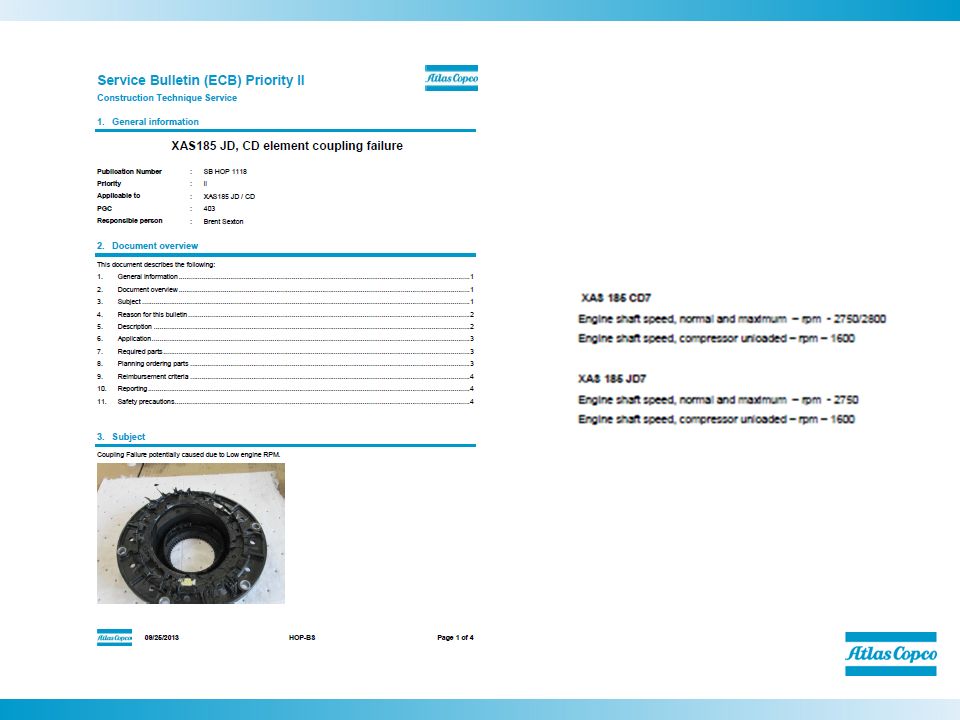
XAS185 JD7 Compressors Scott Malm 1. Committed to sustainable productivity.

2
Hard Hat Version Unit features Two canopy choices
One made from composite material that does not dent or rust Removable side and end panels for easy service Rear mounted controls and discharge valves

3
Standard Version Steel construction
Removable side and end panels for easy service Same rear mounted control panel

4
XAS 185 JD7 Product nomination and grouping Principle data
Compressor systems: Service Kits Warranty

5
Product Nomination Oil Injected Compressors
Nomination and grouping Principle data Compressor systems Running conditions Electrical system Instrument panel Engine supplier C : Caterpillar D : Deutz J : John Deere K : Kabota Working principle A : Single stage compressor R : Two stage compressor Product range X : Oil injected portable compressor Silencing : Un-silenced S : Silenced Prime mover d : diesel engine E : electric motor X A T S 185 J D 7 Capacity (FAD) Liter/sec CFM (US-version) Working pressure : standard pressure psi T : “ten” pressure psi H : high pressure psi
 Liter/sec CFM (US-version) Working pressure. : standard pressure 102psi. T : ten pressure 150psi. H : high pressure 175psi.")
6
Nomination and grouping
Principle Data Nomination and grouping Principle data Compressor systems Running conditions Electrical system Instrument panel

7
Nomination and grouping
Compressor Systems Nomination and grouping Principle data Compressor systems Running conditions Electrical system Instrument panel *4 major systems Air system Oil system Regulating system Electrical system This figure shows you the compressor systems and their parts. Basically, a compressors consists of three systems: the air system, the oil system and the regulating system. You can click on one of the three titles to find out more about that particular system.

8
Air system The following slides explain how the regulating system of the XA(H)S works. They will give you an overview of the different parts and their function.
S works. They will give you an overview of the different parts and their function.")
9
Nomination and grouping
Air System Nomination and grouping Principle data Compressor systems Running conditions Electrical system Instrument panel Air filter Unloading valve Compressor element Check valve Air receiver Minimum pressure nozzle Air outlet valve The following slides explain how the regulating system of the XA(H)S works. They will give you an overview of the different parts and their function.
S works. They will give you an overview of the different parts and their function.")
10
Nomination and grouping
Air Filter Nomination and grouping Principle data Compressor systems Running conditions Electrical system Instrument panel Air inlet Centrifugal separation Dust Filter element to compressor element Vacuum indicator The following slides explain how the regulating system of the XA(H)S works. They will give you an overview of the different parts and their function.
S works. They will give you an overview of the different parts and their function.")
11
Air Filter Filtration of the inlet air in 2 stages :
Centrifugal dust separation Paper filter element Optional safety element Air filter vacuum indicator Safety Filter XAS 185 JD Compressor Engine

12
Nomination and grouping
Unloading Valve Nomination and grouping Principle data Compressor systems Running conditions Electrical system Instrument panel Opens and closes the air inlet to the compressor element. Open position at load condition => Air demand. Closed position at no load condition => No air demand. Valve is controlled by the regulating pressure. The following slides explain how the regulating system of the XA(H)S works. They will give you an overview of the different parts and their function.
S works. They will give you an overview of the different parts and their function.")
13
Nomination and grouping
Unloading Valve Nomination and grouping Principle data Compressor systems Running conditions Electrical system Instrument panel Regulating pressure Air inlet Spring loaded Vent Hole The following slides explain how the regulating system of the XA(H)S works. They will give you an overview of the different parts and their function. Integrated blow-down valve Valve
S works. They will give you an overview of the different parts and their function. Integrated. blow-down valve. Valve.")
14
Nomination and grouping
Unloading Valve Nomination and grouping Principle data Compressor systems Running conditions Electrical system Instrument panel LOAD Regulating pressure UNLOAD The following slides explain how the regulating system of the XA(H)S works. They will give you an overview of the different parts and their function. Air inlet
S works. They will give you an overview of the different parts and their function. Air inlet.")
15
Nomination and grouping
Compressor Element Nomination and grouping Principle data Compressor systems Running conditions Electrical system Instrument panel The following slides explain how the regulating system of the XA(H)S works. They will give you an overview of the different parts and their function.
S works. They will give you an overview of the different parts and their function.")
16
Compressor Coupler

18
Nomination and grouping
Compressor Element Nomination and grouping Principle data Compressor systems Running conditions Electrical system Instrument panel The following slides explain how the regulating system of the XA(H)S works. They will give you an overview of the different parts and their function. Oil is injected in the bottom of the rotor housing, on the bearings and gears
S works. They will give you an overview of the different parts and their function. Oil is injected in the bottom of the rotor housing, on the bearings and gears.")
19
Nomination and grouping
Compressor Element Nomination and grouping Principle data Compressor systems Running conditions Electrical system Instrument panel Oil Air/Oil Air inlet The following slides explain how the regulating system of the XA(H)S works. They will give you an overview of the different parts and their function.
S works. They will give you an overview of the different parts and their function.")
20
Nomination and grouping
Check Valve Nomination and grouping Principle data Compressor systems Running conditions Electrical system Instrument panel Check valve is integrated in the Unloader XAS 185 JD compressor. Closed when the compressor is stopped. The air receiver is pressurized, which would result in a reverse air flow. the check valve prevents this. The following slides explain how the regulating system of the XA(H)S works. They will give you an overview of the different parts and their function.
S works. They will give you an overview of the different parts and their function.")
21
Nomination and grouping
Check Valve Nomination and grouping Principle data Compressor systems Running conditions Electrical system Instrument panel Valve Part # LOAD SHUT-DOWN Receiver pressure When compressor is shut-down Check valve The following slides explain how the regulating system of the XA(H)S works. They will give you an overview of the different parts and their function.
S works. They will give you an overview of the different parts and their function.")
22
Nomination and grouping
Air Receiver Nomination and grouping Principle data Compressor systems Running conditions Electrical system Instrument panel Air/Oil Centrifugal Separation Air outlet Separator Element The following slides explain how the regulating system of the XA(H)S works. They will give you an overview of the different parts and their function.
S works. They will give you an overview of the different parts and their function.")
23
Minimum Pressure Nozzle
Nomination and grouping Principle data Compressor systems Running conditions Electrical system Instrument panel NOZZLE Guarantees a minimum pressure in the receiver tank (approx. 45 – 60 psi) Minimum pressure is required to guarantee a continuous oil supply to the element. The following slides explain how the regulating system of the XA(H)S works. They will give you an overview of the different parts and their function.
 Minimum pressure is required to guarantee a continuous oil supply to the element. The following slides explain how the regulating system of the XA(H)S works. They will give you an overview of the different parts and their function.")
24
OIL SYSTEM The following slides explain how the regulating system of the XA(H)S works. They will give you an overview of the different parts and their function.
S works. They will give you an overview of the different parts and their function.")
25
Nomination and grouping
Oil System Nomination and grouping Principle data Compressor systems Running conditions Electrical system Instrument panel Air receiver Oil cooler Oil filter Compressor element Oil separator Scavenge line The following slides explain how the regulating system of the XA(H)S works. They will give you an overview of the different parts and their function.
S works. They will give you an overview of the different parts and their function.")
26
Nomination and grouping
Air Receiver Nomination and grouping Principle data Compressor systems Running conditions Electrical system Instrument panel Oil flow Pressure The following slides explain how the regulating system of the XA(H)S works. They will give you an overview of the different parts and their function. No Compressor Oil Pump Necessary
S works. They will give you an overview of the different parts and their function. No Compressor Oil Pump Necessary.")
27
Nomination and grouping
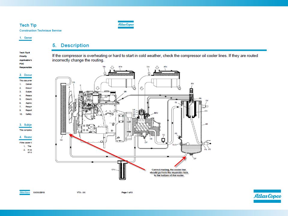
Oil Cooler Nomination and grouping Principle data Compressor systems Running conditions Electrical system Instrument panel Warm Oil Cooling air Cool Oil The following slides explain how the regulating system of the XA(H)S works. They will give you an overview of the different parts and their function. Oil Temp Should Have no more than 40 F Drop Through The Cooler – Use Proper Oil and Filters
S works. They will give you an overview of the different parts and their function. Oil Temp Should Have no more than 40 F Drop Through The Cooler – Use Proper Oil and Filters.")
29
Nomination and grouping
Oil Filter Nomination and grouping Principle data Compressor systems Running conditions Electrical system Instrument panel Dirty Oil Filtered Oil By-pass valve By pass valve opens at 36 PSI Ensures sufficient lubrication And cooling if the filter gets clogged The following slides explain how the regulating system of the XA(H)S works. They will give you an overview of the different parts and their function. Part #
S works. They will give you an overview of the different parts and their function. Part #")
30
Nomination and grouping
Compressor Element Nomination and grouping Principle data Compressor systems Running conditions Electrical system Instrument panel Oil Air/Oil Lubrication to the bearings Air inlet The following slides explain how the regulating system of the XA(H)S works. They will give you an overview of the different parts and their function. Scavenged oil
S works. They will give you an overview of the different parts and their function. Scavenged oil.")
31
Oil Separator & Scavenge Line
Nomination and grouping Principle data Compressor systems Running conditions Electrical system Instrument panel * Centrifugal force removes about 85% of the oil Change of direction, about 99% of the oil After separator element at discharge will be 3 to 5 PPM. Air/Oil Centrifugal separation Separator Element Oil Scavenge line **Make sure the scavenge line runs ALONG SIDE the air outlet tube and NOT in the air outlet** When changing the separator element the retainer must be cleaned Also works as ground The following slides explain how the regulating system of the XA(H)S works. They will give you an overview of the different parts and their function.
S works. They will give you an overview of the different parts and their function.")
32
Oil Separator Separator Kit Part Number 2911 0068 00
Classic Reasons For Oil Carryover Over filled receiver Plugged scavenge line or restricted orifice Wrong type of oil (no anti foam agent and anti-corrosion additives) Shut down with air outlet valves open (Only On XAS 185) Scavenge tube installed improperly (in outlet tube) Used incorrectly for application (Sandblasting) Separator Kit Part Number
 Shut down with air outlet valves open (Only On XAS 185) Scavenge tube installed improperly (in outlet tube) Used incorrectly for application (Sandblasting) Separator Kit Part Number")
33
REGULATING SYSTEM The following slides explain how the regulating system of the XA(H)S works. They will give you an overview of the different parts and their function.
S works. They will give you an overview of the different parts and their function.")
34
Nomination and grouping
Regulating System Nomination and grouping Principle data Compressor systems Running conditions Electrical system Instrument panel Regulating valve Unloading valve Speed regulator Blow-down valve Safety valve Regulating Valve Unloading Valve Speed Regulator Safety Valve The following slides explain how the regulating system of the XA(H)S works. They will give you an overview of the different parts and their function.
S works. They will give you an overview of the different parts and their function.")
35
Nomination and grouping
Regulating Valve Nomination and grouping Principle data Compressor systems Running conditions Electrical system Instrument panel Regulates the effective pressure in the air receiver Provides regulating pressure to : unloading valve => regulates the air inlet according the air demand speed regulator => regulates the engine speed to reduce fuel consumption Regulating Valve Part Number The following slides explain how the regulating system of the XA(H)S works. They will give you an overview of the different parts and their function.
S works. They will give you an overview of the different parts and their function.")
36
Nomination and grouping Adjusts Unload Pressure
Regulating Valve Nomination and grouping Principle data Compressor systems Running conditions Electrical system Instrument panel UNLOAD LOAD Adjusts Unload Pressure Control Pressure Pressure Gauge To speed reg The following slides explain how the regulating system of the XA(H)S works. They will give you an overview of the different parts and their function. To unloading valve To blow down valve Scavenge line Receiver Pressure
S works. They will give you an overview of the different parts and their function. To unloading valve. To blow down valve. Scavenge line. Receiver Pressure.")
37
Nomination and grouping
Speed Regulator Nomination and grouping Principle data Compressor systems Running conditions Electrical system Instrument panel Regulates the engine speed in relation to the required air demand Load condition : maximum engine speed Unload condition : minimum engine speed Reg. will adjust the engine speed to match air demand Speed Regulator part number The following slides explain how the regulating system of the XA(H)S works. They will give you an overview of the different parts and their function.
S works. They will give you an overview of the different parts and their function.")
38
Nomination and grouping
Speed Regulator Nomination and grouping Principle data Compressor systems Running conditions Electrical system Instrument panel Control air Control air The following slides explain how the regulating system of the XA(H)S works. They will give you an overview of the different parts and their function. Vent Vent Max Speed Idle Speed
S works. They will give you an overview of the different parts and their function. Vent. Vent. Max Speed. Idle Speed.")
39
Nomination and grouping
Blow Down Valve Nomination and grouping Principle data Compressor systems Running conditions Electrical system Instrument panel Blows off the air receiver pressure once the compressor has shut-down => this is to depressurize the receiver tank Integrated in the unloading valve The following slides explain how the regulating system of the XA(H)S works. They will give you an overview of the different parts and their function.
S works. They will give you an overview of the different parts and their function.")
40
Unloading Valve – Cut Away
Blow Down Valve

41
Nomination and grouping
Blow Down Valve Nomination and grouping Principle data Compressor systems Running conditions Electrical system Instrument panel LOAD / UNLOAD BLOW-DOWN Blow-off receiver pressure Receiver pressure Receiver Pressure The following slides explain how the regulating system of the XA(H)S works. They will give you an overview of the different parts and their function. blow-down valve
S works. They will give you an overview of the different parts and their function. blow-down valve.")
42
Nomination and grouping
Safety Valve Nomination and grouping Principle data Compressor systems Running conditions Electrical system Instrument panel Blows off the air receiver pressure when it exceeds the preset value. Protects the compressor and engine. XAS 185 JD PSI The following slides explain how the regulating system of the XA(H)S works. They will give you an overview of the different parts and their function.
S works. They will give you an overview of the different parts and their function.")
43
Compressor Running Conditions
Nomination and grouping Principle data Compressor systems Running conditions Electrical system Instrument panel Major running conditions : UNLOAD Receiver tank pressurized, no air being used LOAD Receiver tank pressurized, air is being used BLOW-DOWN Machine stopped, blow-off of receiver pressure There are four states the compressor can be in: lo-load, unload, load and blow down. Each condition is explained in detail in the following pages.

44
Electrical System

45
Nomination and grouping
Electrical System Nomination and grouping Principle data Compressor systems Running conditions Electrical system Instrument panel 12 Volts DC Alternator has built in voltage regulator B+ Positive to recharge battery B- Ground W Frequency for tachometer (optional) D+ Ground when alternator is turning less than 650RPM 12 Volts when turning more than 650 RPM Cuts-out starter motor when engine is running through K4 relay
 D+ Ground when alternator is turning less than 650RPM. 12 Volts when turning more than 650 RPM. Cuts-out starter motor when engine is running through K4 relay.")
46
Nomination and grouping
Electrical System Nomination and grouping Principle data Compressor systems Running conditions Electrical system Instrument panel Safety shut-downs Compressor : Compressor element outlet temperature (255ºF) – Engine : Coolant temperature (221ºF) Oil pressure (17psi) Low fuel level (5%) Alternator not charging Fail safe as a loose wire will result in a shut-down Good electrical contacts are important
 – Engine : Coolant temperature (221ºF) Oil pressure (17psi) Low fuel level (5%) Alternator not charging. Fail safe as a loose wire will result in a shut-down. Good electrical contacts are important.")
47
Electrical System / Std Unit - XAS 185 JD7
Nomination and grouping Principle data Compressor systems Running conditions Electrical system Instrument panel

48
Switch In The Off Position
1

49
Switch In The On Position
Start button S1 position 1: Line 2 on 12V contact K3 closed (30-87), lamp H2 is on. K4 excites contact K4 (87-87a). Thermocontact element S5 normally closed, K1 excites contact K1 (30-87). 2
, lamp H2 is. on. K4 excites contact K4 (87-87a). Thermocontact. element S5 normally closed, K1 excites contact K1. (30-87). 2.")
50
Switch In The On Position S-4 Cold Start Pressed
Use of preheat: Start button S1 position 1 press pushbutton S4, energizes relay K5 and provides power to the glowplug. 3

51
Switch In The # 2 Position
Start button S1 position 2: Line 3 on 12V (override function) hourmeter P1, and fuel solenoid Y1 is excited. Thermocontact engine S2 normally closed, oil pressure contact S3 open. 4
 hourmeter P1, and. fuel solenoid Y1 is excited. Thermocontact engine S2. normally closed, oil pressure contact S3 open. 4.")
52
Switch In The Start Position
Start button S1 position 3: Start relay K0 is excited and starter motor is running, engine builds up oil pressure and oil pressure contact S3 closes. K3 excited and contact K3 changes over to (30-87). Relay K2 no longer excited, contact K2 opens, lamp H1 goes out. Alternator also commences supplying voltage and K4 is no longer excited and contact K4 changes over to (87-87a). Lamp H2 goes out, one can release start button S1 and it returns to position 1. Exciting the safety devices occurs no longer across line 3 but across line 2 to line 4 and this way to line 3. 5
. Relay K2 no longer excited, contact K2. opens, lamp H1 goes out. Alternator also commences. supplying voltage and K4 is no longer excited and. contact K4 changes over to (87-87a). Lamp H2 goes. out, one can release start button S1 and it returns to. position 1. Exciting the safety devices occurs no. longer across line 3 but across line 2 to line 4 and this. way to line")
53
Switch Back To The On Position- Engine Running
Explanation of shutdowns: Oil pressure contact S3 opens, K3 no longer excited. K3 changes over (87a-87), engine cuts out because fuel solenoid Y1 no longer excited and lamp H2 goes on simultaneously. Thermocontact S2 opens, K3 no longer excited. K3 changes over (87a-87), engine cuts out because fuel solenoid Y1 no longer excited and lamp H2 goes on simultaneously. Thermocontact S5 opens, K1 no longer excited. Contact K1 changes over (87-87a). K3 no longer excited. K3 changes over (97a-87), engine cuts out because fuel solenoid Y1 no longer excited and lamp H2 and H1 go on simultaneously. Take-over relay K2 is excited simultaneously with H1 and contact K2 closes (30-87). Thermocontact S5 cools off and closes, K1 excited again and contact K1 changes over (87-87a). However, lamp H1 remains on across line 9 and contact K2 (30-87). A fault in the alternator part causes terminal D+ to go to 0V and K4 to be excited. Contact K4 changes over to (87a- 87), engine cuts out because fuel solenoid Y1 no longer excited and lamp H2 goes on simultaneously. 6
, engine cuts out because. fuel solenoid Y1 no longer excited and lamp H2 goes. on simultaneously. Thermocontact S2 opens, K3 no longer excited. K3. changes over (87a-87), engine cuts out because fuel. solenoid Y1 no longer excited and lamp H2 goes on. simultaneously. Thermocontact S5 opens, K1 no longer excited. Contact K1 changes over (87-87a). K3 no longer. excited. K3 changes over (97a-87), engine cuts out. because fuel solenoid Y1 no longer excited and lamp. H2 and H1 go on simultaneously. Take-over relay K2. is excited simultaneously with H1 and contact K2. closes (30-87). Thermocontact S5 cools off and closes, K1 excited. again and contact K1 changes over (87-87a). However, lamp H1 remains on across line 9 and. contact K2 (30-87). A fault in the alternator part causes terminal D+ to go to 0V. and K4 to be excited. Contact K4 changes over to (87a- 87), engine cuts out because fuel solenoid Y1 no longer. excited and lamp H2 goes on simultaneously. 6.")
54
Control Panel Ignition Switch General Alarm Lamp Comp Temp Lamp

55
Control panel is Mounted at the rear of the unit More visible and user friendly

56
10 AMP Circuit Breaker Behind Control Panel
Working Pressure Compressor temp Cold Start Fuel Gage Hour Meter 10 AMP Circuit Breaker Behind Control Panel General alarm Ignition Switch Coldstart

59
Service Kits XAS 185 CD Kit number Designation 2911 0051 00 Unloader
Speed Reg.(Piston Seal) Speed Reg.(Wiper) Oil separator
 Speed Reg.(Wiper) Oil separator.")
60
Preventive Maintenance Filter Kits
60. Atlas Copco in Brief The Atlas Copco Group is a global industrial group of companies developing, manufacturing, and marketing products and services to a wide range of customers and end-users. A world leader, the Group provides compressed air and gas equipment, generators, construction and mining equipment, assembly systems, electric and pneumatic tools, and related services and equipment rental. The Atlas Copco Group owns well-known brands such as Atlas Copco, RSC, Prime Energy, Chicago Pneumatic. The head office is in Stockholm, Sweden. The Group has approximately employees in some 70 countries. In 2003, the Group reached revenues of MSEK with 98% of revenues outside Sweden.

61
Spare Parts Recommendation

62
Maintenance DAILY Check engine oil level Check compressor oil level
Check air filter vacuum indicator Empty air filter vacuator valve

63
Maintenance 50 HOURS Change compressor spin on filter (2914 5050 00)
Check battery terminals (Load Test) Check tire pressure / re-torque wheel lug nuts Check drawbar bolts Check for leaks in the air, fuel, and oil system Check engine minimum (1600) / maximum (2750) RPM Lubricate door hinges / locks / etc.
 Check tire pressure / re-torque wheel lug nuts. Check drawbar bolts. Check for leaks in the air, fuel, and oil system. Check engine minimum (1600) / maximum (2750) RPM. Lubricate door hinges / locks / etc.")
64
Maintenance 250 Hours Perform 50 hour maintenance plus:
Change engine oil and filter Clean the oil cooler / radiator Clean fuel tank Change fuel filters

65
Maintenance 500 Hours/Annually Perform the 250 hour maintenance plus:
Change compressor oil spin on filter Check/Replace air filter elements

66
Maintenance 1000 Hours/Annually Perform 500 hour maintenance plus:
Adjust valves on engine Replace Air oil separator Test safety valve Test operation of engine and compressor Test safety switches and relays Repack or Grease wheel bearings

67
Torque values SAE Grade 5 SAE Grade 8

68
Special Torque values Wheel nuts 59 lb.ft (+7-0)
Axle - beams lb.ft (+/-7) Drawbar - axle lb.ft (+/-7) Drawbar - bottom 59 lb.ft (+/-7) Towing eye - drawbar 59 lb.ft (+/-7) Lifting eye - flywheel housing 151 lb.ft (+15/-0) Engine - drive housing (M12) 59 lb.ft (+/-7) Engine - drive housing (M14) 92 lb.ft (+/-7) Compressor - drive housing 59 lb.ft (+/-4) Safety switches lb.ft (+/-4)
 Drawbar - axle 59 lb.ft (+/-7) Drawbar - bottom 59 lb.ft (+/-7) Towing eye - drawbar 59 lb.ft (+/-7) Lifting eye - flywheel housing 151 lb.ft (+15/-0) Engine - drive housing (M12) 59 lb.ft (+/-7) Engine - drive housing (M14) 92 lb.ft (+/-7) Compressor - drive housing 59 lb.ft (+/-4) Safety switches 26 lb.ft (+/-4)")
69
Warranty – Compressors – Replacement Parts
Atlas Copco portable air compressors are warranted to be free from defects with regard to materials and workmanship for the period of fifteen (15) months from date of shipment from the factory, or twelve (12) months from date of initial startup, whichever occurs first, without limitation in running hours. All Spare Parts are sold with a 90 day warranty unless otherwise specified.
 months from date of shipment from the factory, or twelve (12) months from date of initial startup, whichever occurs first, without limitation in running hours. All Spare Parts are sold with a 90 day warranty unless otherwise specified.")
70
Warranty – Air Compressor Elements
Air compressor elements and gearbox assemblies used in Atlas Copco portable air compressors, are warranted to be free from defects with regard to materials and workmanship for the period of thirty-nine (39) months from date of shipment from the factory, or thirty-six (36) months from date of initial startup, whichever occurs first, without limitation in running hours. This is provided only Atlas Copco kits and fluids are used throughout this period. Replacement of Elements In the event that there is a need to replace an element it will be warranted for 12 months or the balance of the machine warranty which ever is greater. Extended warranty of 5 years 10,000 Hrs. on compressor element and gearbox assemblies provided only Atlas Copco kits and fluids are used throughout the 5 year period at the maintenance intervals indicated in the instruction manual.
 months from date of shipment from the factory, or thirty-six (36) months from date of initial startup, whichever occurs first, without limitation in running hours. This is provided only Atlas Copco kits and fluids are used throughout this period. Replacement of Elements. In the event that there is a need to replace an element it will be warranted for 12 months or the balance of the machine warranty which ever is greater. Extended warranty of 5 years 10,000 Hrs. on compressor element and gearbox assemblies provided only Atlas Copco kits and fluids are used throughout the 5 year period at the maintenance intervals indicated in the instruction manual.")
72
Warranty - Engines John Deere –
1 year unlimited hours or 2 years 2000 hours whichever occurs first. Extended engine warranties may be purchased through the local engine dealers.

75
Committed to sustainable productivity.

Similar presentations