Download presentation
Presentation is loading. Please wait.

1
By: Uriel Barron Matan Schlanger Supervisor: Mony Orbach Final Review March 2015

2
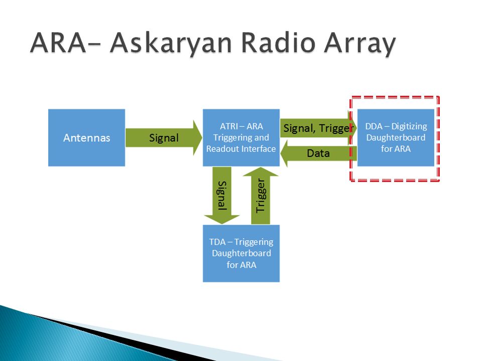
Large Neutrino detector at the South Pole A collaboration of 11 universities worldwide Detection of short, extremely weak RF pulses over an area of 100km 2

4
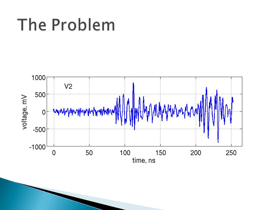
High Bandwidth (~850 MHz), rare (once every few months) and short (~100 ns) pulses Strong price sensitivity – At least 37 stations, high frequency samplers cost thousands of dollars per channel Power consumption requirements (~2W)– limited power at the South Pole Sample 4 channels with one board
, rare (once every few months) and short (~100 ns) pulses Strong price sensitivity – At least 37 stations, high frequency samplers cost thousands of dollars per channel Power consumption requirements (~2W)– limited power at the South Pole Sample 4 channels with one board")
6
LABRADOR – basic digitizing board for the ARA test bed, only 1 GSPS IRS (Ice Radio Sampler) – series of ASICs created for the DDA Best so far – IRS2, which can sample in 4 GSPS, but has a long dead time
 – series of ASICs created for the DDA Best so far – IRS2, which can sample in 4 GSPS, but has a long dead time")
7
Design and simulate a low-cost sampler for high frequency short pulses, with low power consumption Design will include BOM, electronic schematics, layers design and Gerber files

9
Dead time < 1ms Build-in EEPROM and temperature sensor Standby power consumption < 1W Low cost (exact price isn’t specified)
")
10
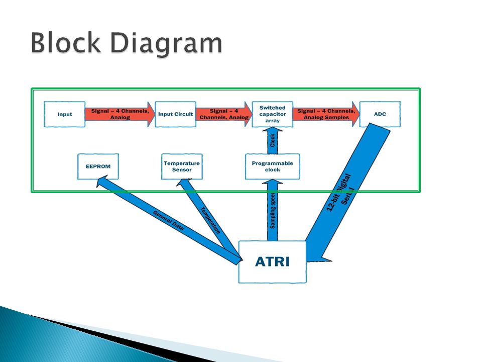
Using a DRS4 Domino Wave Circuit to quickly save analogously ~2000 sample per channel Instead of continuous high-frequency sampling, using regular ADCs All components are on-the-shelf and significantly cheaper than high-frequency samplers.

12
Using the domino effect to save analog high- frequency signals, and later digitize them slowly Contains 8 channels, each channel can save up to 1024 samples Supports cascading of channels Sample speed is up to 5 GSPS

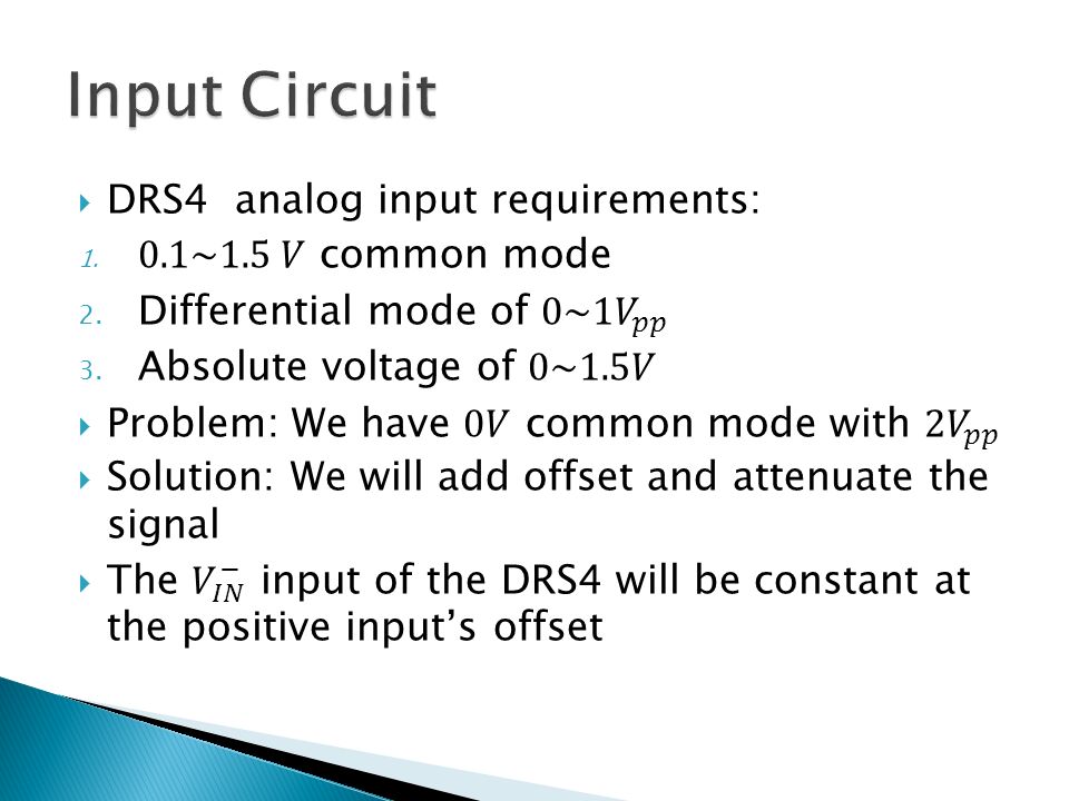
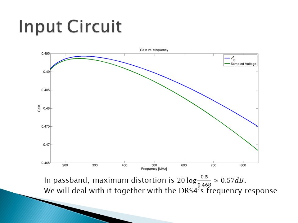
16
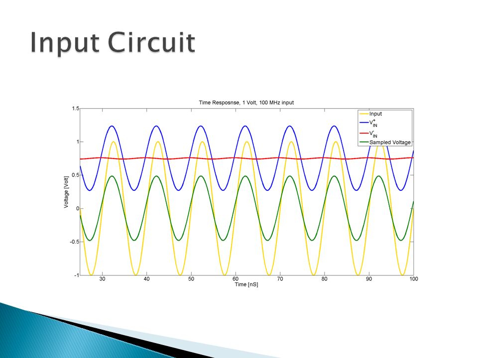
We have a little distortion, but…

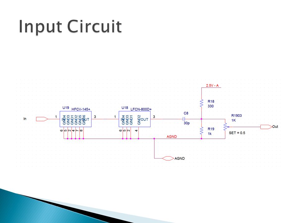
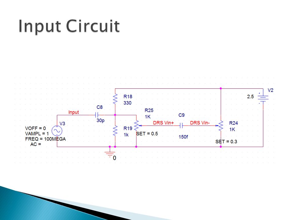
18
The input circuit works well, and consumes 7.5mW per channel, which yield 30mW total power consumption.

23
Recommended in the DRS4’s datasheet, because the DRS4’s output can be connected directly to the AD9222 inputs 8 channels, can shut down each channels to reduce the power dissipation to virtually 0 with short waking-up time 12-bit, serial outputs

25
3 Supply voltages: 1. 3.3V – Clock and peripheral components 2. 2.5V – DRS4 3. 1.8V – ADC We will use regulators to get 2.5V and 1.8V Total power dissipation of 300mW when idle, about 720mW during sampling bursts

26
We don’t have such voltage rises, so we’re fine with our bypass capacitors

27
Backward compatibility – QSE connectors location is fixed, SMA connectors on the other side DRS4 and ADC – according to design flow Clock – near the DRS4’s clock input Peripheral components and regulators – wherever convenient

28
Filters Regulators Clock EEPROM Temperature Sensor

29
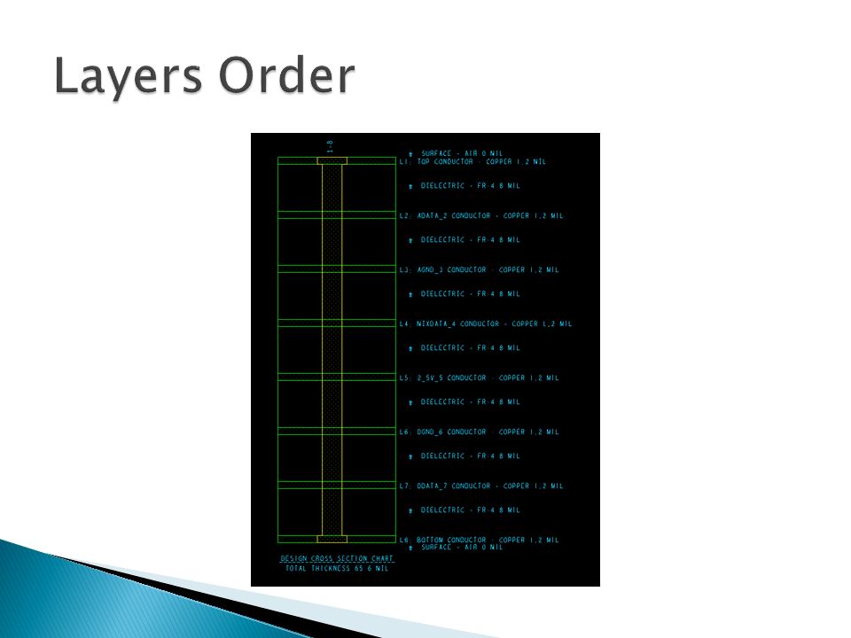
Main goal – shield the vulnerable analog signals from any external noises or crosstalk with digital signals We will use 8 layers, since there’s no strict limit over the cost, and we can get better performances This makes much room for shielding using fully conductive layers (power and ground)
")
30
1. Top – 1.8V and some wires near components 2. Analog Data 3. Analog Ground 4. Mixed data – general use 5. 2.5V – both analog and digital 6. Digital Ground 7. Digital Data 8. Bottom – mostly connectors

32
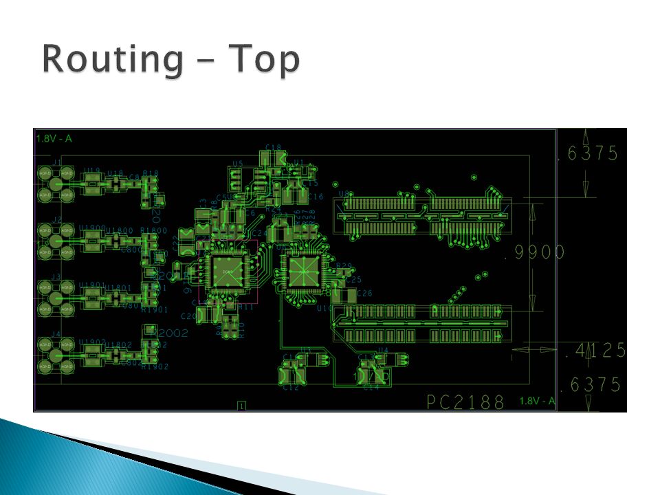
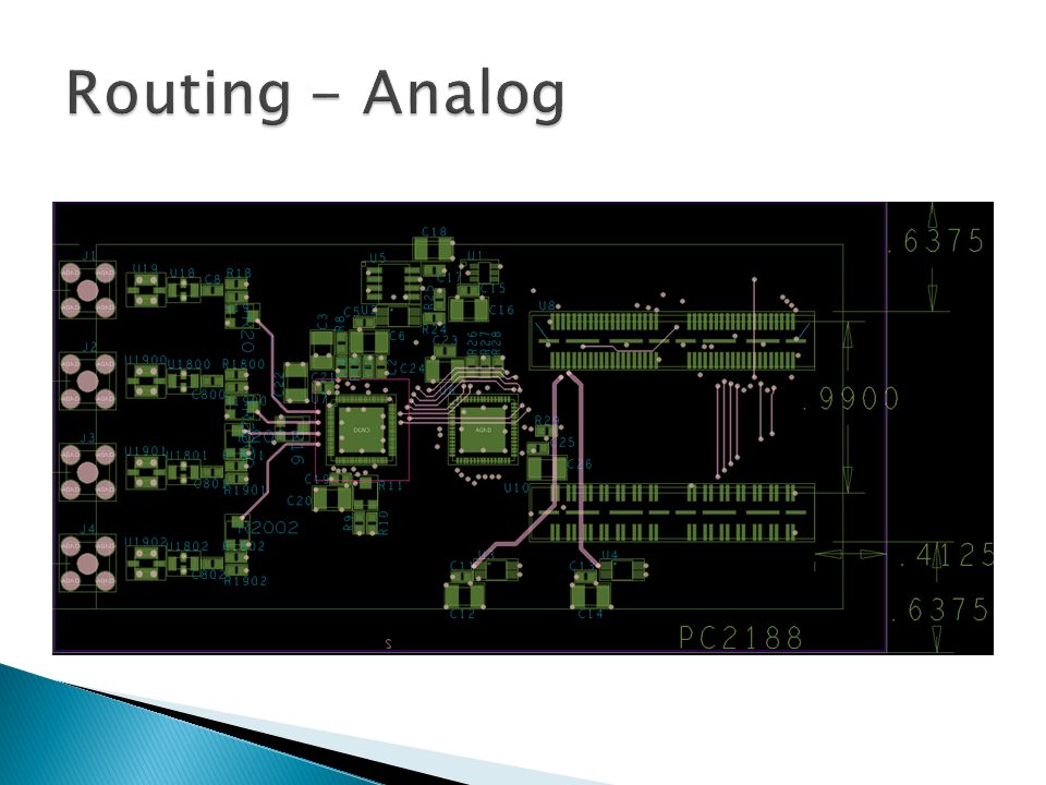
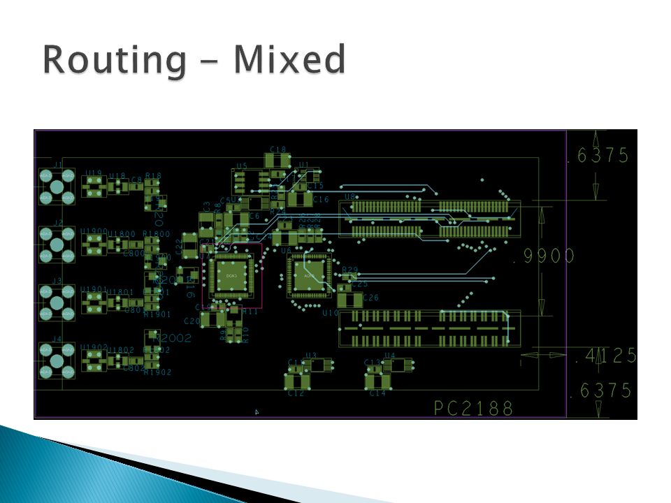
Most important – isolating analog signals from any noise This means using mixed data for analog signals only when there is no other option Another consideration – length of analog signals, differential pairs and clock-data pairs should be the same

33
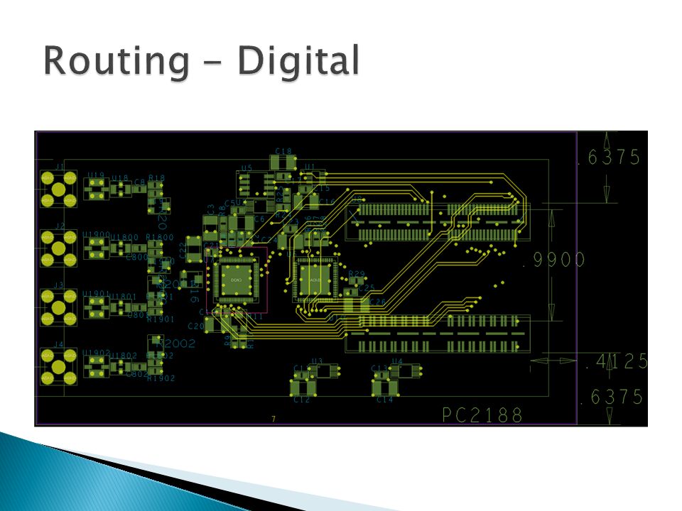
Top, Analog, Mixed, Digital

38
We managed to make an almost complete separation between analog and digital layers. Therefore, we can change the layers order to get an even better isolation No crosstalk between analog and digital signals Differences in analog lines’ length is completely negligible

39
1. Top - 1.8V 2. Analog Data 3. Analog Ground 4. 2.5V 5. Digital Data 2 – Former “mixed data” 6. Digital Ground 7. Digital Data 8. Bottom

41
We used only reliable on-the-shelf products 900 MSPS to 5 GSPS sampling speed Approximate power consumption of 300mW when idle, 720mW during sampling bursts Strong shielding of analog signals Approximate cost of 216$, instead of 8000$ Dead time: 66μs

42
Better input circuit with op-amps Reduce to 6 layers board Use advanced readout modes to reduce dead time Integrate 2 DRS4s Adapt the DRS5

Similar presentations


 High Speed Signal Processing Board Design By: Nir Malka, Lior Rom Instructor: Mike Sumszyk הטכניון - מכון טכנולוגי לישראל הפקולטה.>")


.>")
