Download presentation
Presentation is loading. Please wait.

1
The Cut Cone

2
The given views show the Front Elevation and part Plan of a cut cone. Draw the following views :- Complete Plan End Elevation Development True Shape of cut

3
Start drawing the End Elevation by projecting the height and width from the given views.

4
Use 30 º and 60 º lines to divide the Plan into 12 equal parts. 1 2 3 4 5 6 7 8 9 10 12 11 Number each of the points on the Plan.

5
Project each of the points from the Plan onto the Elevation base. 12 3 45678 9 1011 12 1 2 3 4 5 6 7 8 9 10 12 11 Number each of the points on the Elevation making sure that the numbers correspond with those on the Plan.

6
12 11 10 9 8 7 6 5 4 3 2 1 Draw generators from the apex of the cone to each of the points found on the base of the cone. 12 3 45678 9 1011 12

7
11 10 9 8 7 6 5 4 3 2 1 9 10 8 11 7 12 6 1 5 2 4 3 Project the position of the generators onto the End Elevation by projecting the points from the Plan. 6 5 8 43 10 2 11 1 12 7 9 Number each of the points on the End Elevation. Draw generators from the apex to the base.

8
Project the points where the generators on the Elevation cross the cut onto the End Elevation. 12 11 10 9 8 7 6 5 4 3 2 1 9 10 8 11 7 12 6 1 5 2 4 36 5 8 43 2 11 1 12 7 9 Mark each of the points found with a small dot.

9
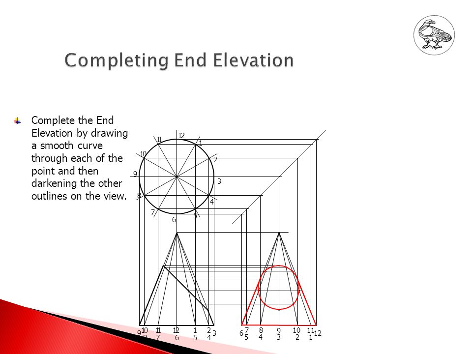
12 11 10 9 8 7 6 5 4 3 2 1 Complete the End Elevation by drawing a smooth curve through each of the point and then darkening the other outlines on the view. 9 10 8 11 7 12 6 1 5 2 4 36 5 8 43 10 2 11 1 12 7 9
10
Project the points from the cut on the Elevation up to the correct generator lines on the Plan. (Note that points 6 and 12 will not be able to be found at this time.) 12 11 10 9 8 7 6 5 4 3 2 1 9 10 8 11 7 12 6 1 5 2 4 3 6 5 8 43 10 2 11 1 12 7 9 Mark each of the points found with a small dot
 Mark each of the points found with a small dot.")
11
Project point 6 and 12 onto the outside generator on the Elevation. 1 11 7 6 10 9 8 9 10 8 11 7 12 6 2 5 4 3 2 1 1 5 2 4 3 6 7 5 8 4 9 3 10 2 11 1 12 Project this point up to the centre line of the Plan. Use compasses to rotate this point onto the correct generators for points 6 and 12. Mark each of these points with a small dot

12
Project points 6 and 12 from the End Elevation onto the correct generators on the Plan. 12 7 6 5 4 87654 4321 9 10111212 3 6 7 5 891011 12 11 10 9 8 3 2 1

13
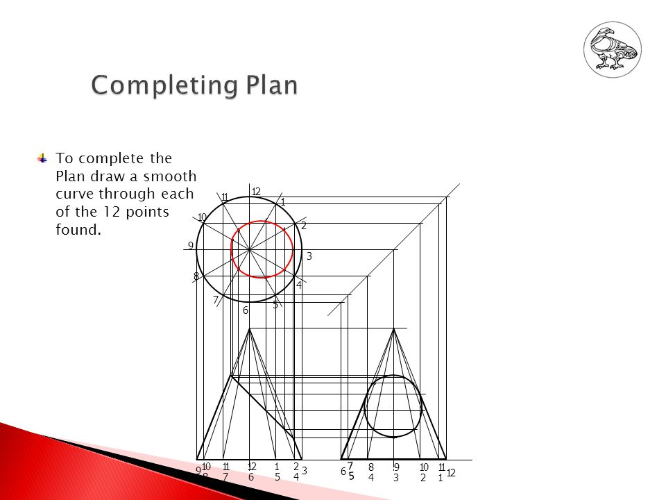
To complete the Plan draw a smooth curve through each of the 12 points found. 12 11 10 9 8 7 6 5 4 3 2 1 9 10 8 11 7 12 6 1 5 2 4 3 6 7 5 8 4 9 3 10 2 11 1 12
14
Mark the position where the apex of the Development will be placed. 12 11 10 9 8 7 6 5 4 3 2 1 9 10 8 11 7 12 6 1 5 2 4 3 6 7 5 8 4 9 3 10 2 11 1 12 3 4 5 6 7 8 9 10 11 12 1 9 2 Draw the first generator. Draw the base line of the Development. Step off the size to each generator point along the base. Number each of the points found. Draw generator lines from the apex to each of the points on the base.

15
Mark each of the found points with a small dot. 1 5 2 4 3 9 10 8 11 7 12 6 12 11 10 9 8 7 6 5 4 3 2 1 6 7 5 8 4 9 3 10 2 11 1 12 3 2 12 1 4 5 6 7 8 9 10 11 3 It is necessary to find the ‘true length’ of the cut points along each generator. To find these sizes project a line through each point on the cut of the Elevation to the outside generator.

16
Measure the distance from the apex to each point on the outside generator. 12 11 10 9 8 7 6 5 4 3 2 1 9 10 8 11 7 12 6 1 5 2 4 3 6 7 5 8 4 9 3 10 2 11 1 12 Transfer this size to the correct generator on the Development. Mark each point with a small dot. Draw a smooth curve through each point found. Darken each of the other outlines on the Development. 3 2 12 1 4 5 6 7 8 9 10 11 3

17
Project each of the points on the cut of the Elevation away at right angles to the cut surface. 12 11 10 9 8 7 6 5 4 3 2 1 9 10 8 11 7 12 6 1 5 2 4 3 6 7 5 8 4 9 3 10 2 11 1 12 9 8 11 7 12 6 1 5 2 4 3 10 Draw a datum line on the True Shape – in this case the centre line has been chosen. Number each of the lines projected up to the True Shape. 3 2 12 1 4 5 6 7 8 9 10 11 3

18
Measure the sizes from the cut points to the centre line on the Plan and transfer each of these sizes to the correct lines on the True Shape. Note – These sizes can also be measured from the End Elevation. Mark each of the points with a small dot. 12 11 10 9 8 7 6 5 4 3 2 1 9 10 8 11 7 12 6 1 5 2 4 3 6 7 5 8 4 9 3 10 2 11 1 12 9 8 11 7 12 6 1 5 2 4 3 10 3 2 12 1 4 5 6 7 8 9 10 11 3

19
To finish the True Shape draw a smooth curve through each of the points found. 12 11 10 9 8 7 6 5 4 3 2 1 9 10 8 11 7 12 6 1 5 2 4 3 6 7 5 8 4 9 3 10 2 11 1 12 9 8 11 7 12 6 1 5 2 4 3 10 The final drawing should look like this. 3 2 12 1 4 5 6 7 8 9 10 11 3

Similar presentations


. Cut Square Pyramid - Problem The given views show the Front Elevation and unfinished Plan of a cut square pyramid. Draw the following.>")