Download presentation
Presentation is loading. Please wait.

1
Lecture 6: Flight Instruments
AVIATION HISTORY Lecture 6: Flight Instruments

2
Introduction History The very first aircraft had little or no flight instruments All weather flying was risky Navigation depended on pilot’s ability to use landmarks

3
Flying Instrument As airmail pilots began flying at night and in all kinds of weather in 1920’s, new instruments were developed to enable the aircraft to fly. Night Flight Advantages: Air smoother Less air traffic May be easier to detect other aircraft due to aircraft lights Disadvantages: Difficult to select emergency landing site Difficult to see clouds Difficult to see horizon in poor visibility Difficult to see horizon over large body of open water without any lights on surface Horizontal visibility significantly less than directly down in haze/fog Haze and open water combine to lead to loss of spatial orientation

4
Definition ‘Flight Instruments’
The instruments that used to display aircraft information and to control the orientation of the aircraft during flight. Speed, distance, altitude, attitude, direction, temperature and pressure are measured and the measurements are displayed on display panel in the cockpit

5
Birth of Flight Instruments
Then, on September 24, with Mitchell Field engulfed in fog--Doolittle and Kelsey climbed aboard the NY-2. Doolittle put the hood in place while Kelsey lifted his hands for bystanders to see that it was Doolittle at the controls. The NY-2 began its takeoff roll and soon disappeared into the weather. Doolittle flew away from the field, climbed to 1,000 feet and then turned toward Mitchell Field, navigating on the radio beacon supplied by the National Bureau of Standards. Once he established himself "inbound," he began a gradual descent, landing within a few feet from where he began his historic flight just 15 minutes before. "Fog Peril Overcome," heralded the New York Times. It was a new day for commercial aviation. The principles of instrument flight had been proven and the navigational problems associated with weather were overcome. Birth of Flight Instruments September 24, 1929, First FLYING BLIND performed by Jimmy Doolittle’s. Flying Blind means fly by the aid of Flight Instrument only, without a view outside the cockpit.

6
Early/New Flight Instruments Were Developed
1. Visual radio direction finder Using vibration system to direct the aircraft. The closer the plane is to the beacon, the more intense the vibration. 2. Artificial horizon (Attitude Indicator) Showed the orientation of the flying aircraft in relation to the ground (show how the wings were tilted, show whether aircraft nose up/down /level. 3. Barometric altimeter Showed how far the aircraft above the ground. They will sensitively record the time and therefore the distance from the aircraft to the ground.
 Showed the orientation of the flying aircraft in relation to the ground (show how the wings were tilted, show whether aircraft nose up/down /level. 3. Barometric altimeter. Showed how far the aircraft above the ground. They will sensitively record the time and therefore the distance from the aircraft to the ground.")
7
Why Flight Instruments Important
To enable the aircraft fly through the bad weather conditions and during night. To ensure safety and reliable operation. To give the early warning about any failure of aircraft’s system/part so that the pilot could take the immediate action. For safety and reliable operation The first aircraft instruments is fuel & oil pressure instruments To warn of engine trouble so that the aircraft could be landed before engine failed). As aircraft could fly over considerable distances weather became a problem. Instrument systems were developed to fly through bad weather conditions. Speed, distance, altitude, attitude, direction, temperature and pressure are measured and the measurements are displayed on display panel in the cockpit
. As aircraft could fly over considerable distances weather became a problem. Instrument systems were developed to fly through bad weather conditions. Speed, distance, altitude, attitude, direction, temperature and pressure are measured and the measurements are displayed on display panel in the cockpit.")
8
Basic Flight Instruments

9
F-16 Falcon

10
Vertical Speed Indicator
Six Basic Instruments Airspeed Indicator Attitude Indicator Altimeter Heading Indicator Vertical Speed Indicator Turn Indicator

11
1.Airspeed Indicator Tells the pilot how fast the plane is going.
To shows the aircraft's speed relative to the surrounding air. Speed is measured in knots. The airspeed can be calculated by measuring the differences of air pressure. Air pressure is measure using pitot-static system.

12
2. Altimeter To indicate how high the aircraft is from sea level (altitude). Measured in feet. Also called as Altitude Altimeter. It works by measuring air pressure that enter through pitot-static system. Air pressure increases and decreases as the aircraft descends and climbs Gives the aircraft's height (usually in feet or meters) above some reference level (usually sea-level) by measuring the local air pressure. It is adjustable for local barometric pressure (referenced to sea level) which must be set correctly to obtain accurate altitude readings.
 above some reference level (usually sea-level) by measuring the local air pressure. It is adjustable for local barometric pressure (referenced to sea level) which must be set correctly to obtain accurate altitude readings.")
13
3.Vertical Speed Indicator
To display the vertical speed of the aircraft. It used to maintain proper rate of climb and rate of descend Measured in feet per minute. Rate of change is also measured based on air pressure differences through pitot-static system.

14
Pitot-static System PITOT-TUBE

15
4. Attitude Indicator To show the aircraft's attitude relative to the horizon. Also called as artificial horizon. Shows whether wings are level or not and whether aircraft pitch up or down.

16
4. Attitude Indicator How the attitude indicator works
Uses a gyroscope mounted inside the instrument case Gyroscope is a device, used to provide stability or maintain a fixed orientation The gyro rotates in the horizontal plane in relation to earth’s horizon This happens as the aircraft banks, climbs and descends

17
Gyroscope: Device for measuring or maintaining orientation

18
Attitude Indicator Examples

19
5. Heading Indicator To displays aircraft heading/direction with respect to earth’s magnetic north. Also called directional gyro (Use the gyroscope) When the aircraft turns, the needle indicates which direction it is heading. Measured in degrees (0-north, 90-west, 180-south, and 270-east)
 When the aircraft turns, the needle indicates which direction it is heading. Measured in degrees (0-north, 90-west, 180-south, and 270-east)")
20
6. Turn Indicator To display direction of turn and rate of turn. Use the gyroscope. For example, direction of roll while the aircraft is rolling. Measured in degrees per minute How the turn coordinator works a gyro is mounted at a 30 degree angle inside instrument case as the aircraft turns , applied forces cause the gyro to spin and rotate as this happens, the small plane on the instrument face indicates bank

21
Summary Flight instruments all together have made Navigation easier
Communication easier Fault detection and warning indication possible Take-offs and landings easier and most important flying safer.

22
Question What are the various instruments developed that had enabled aircraft to fly at night and in bad weather. List four flight instruments found in an aircraft cockpit to assist the pilots in flying the aircraft.

23
Modern Flight Instruments
“Glass Cockpit”

24
Flight Deck of Modern Aircraft
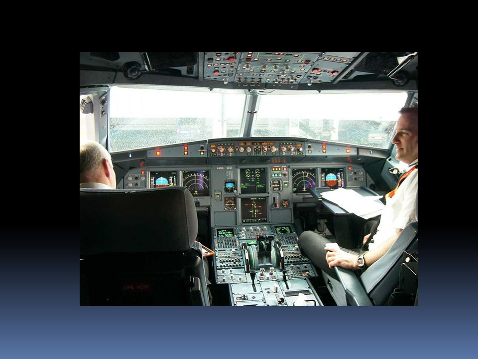
B 777 Flight Deck A 320 – Flight Deck

25
Glass Cockpit History 1970: NASA conducted research on flight instruments displays 1982: The success of the NASA-led glass cockpit work is reflected in the total acceptance of electronic flight displays in Boeing 767. By the end of the 1990s, LCD display panels were increasingly favored among aircraft manufacturers because of their efficiency, reliability and legibility. Nowadays, Modern aircraft such as the Boeing 777, Boeing 787, and Boeing , Boeing ER, Airbus A320 family (enhanced version), Airbus A330, Airbus A340 , Airbus A380 and Airbus A350 are fitted with glass cockpits consisting of liquid crystal display (LCD) units
, Airbus A330, Airbus A340 , Airbus A380 and Airbus A350 are fitted with glass cockpits consisting of liquid crystal display (LCD) units.")
26
Glass Cockpit in Airbus A380

27
Glass Cockpit A glass cockpit is an aircraft cockpit that feature EFIS (Electronic Flight Instrument System) On a glass cockpit aircraft, traditional flight instruments are replaced by an EFIS with six CRT of LCD screens displaying flight information in most convenient form, each screen integrating several instruments. A glass cockpit is an aircraft cockpit that feature EFIS (Electronic Flight Instrument System) Unlike the earlier type of flight instruments, a glass cockpit utilizes several computer displays that can be adjusted to display flight information as needed EFIS installations vary greatly. A light aircraft might be equipped with one display unit, on which are displayed flight and navigation data. A wide-body aircraft is likely to have six or more display units. An EFIS installation will have the following components: Displays Controls Data processors Advantages of the glass cockpit: cleaner appearance larger artificial horizon greater redundancy in case of failure more flexible and accurate navigational options Programmability Perhaps the biggest functional advantage of newer equipment in aircraft is GPS technology. The sorry state of general aviation is that most of us fly 30 year old airplanes, with instruments that use 50 year old technology. Sometimes older. Non-directional beacons are still in use, and that technology is from the 1920's. The result is that now, most pilots who rent airplanes also have a hand-held GPS to take on flights. The downsides to a handheld GPS are size and functionality. They can't be relied on during instrument flight, and the screens are generally very small. A large map screen on the G1000 makes for extremely easy navigation. A basic EFIS might have all these facilities in the one unit. EFIS (Electronic Flight Instrument System) Provides six CRT of LCD screens displaying flight information in most convenient form, each screen integrating several instruments. Displays all information regarding the aircraft’s situation, position and progress. Comprising left- and right-side primary flight display (PFD) and navigation display screens EFIS primarily Electronic Centralized Aircraft Monitor (ECAM) The upper ECAM screen displays engine, flaps setting, fuel quantity and alert information and is named the E/WD (Engine/Warning Display) ; the lower ECAM displays the various systems parameters and is known as the SD (System Display). Classic mechanical backup instruments are still provided (anemometer, artificial horizon and altimeter). Flight Management System (FMS) integrates the several calculators which provide lateral (or surface) and vertical navigation as well as aircraft systems (including engines) management. The interface between the pilot and the FMS is the MCDU (for Multifunction Control Display Unit)which is programmed before the flight and can be reprogrammed at any time during the flight. The Flight Control Unit (FCU) integrates the Autopilot (AP) and Flight Director switches and communicates with the MCDU. Autopilot- Computer device that can fly an airplane on its own, Mostly used on long flights. However, pilot is always present to monitor and check in whether the flight is going according to plan or not. Electronic Altitude Director Indicator (EADI): Tells the pilot whether the airplane is flying level or not.
 Unlike the earlier type of flight instruments, a glass cockpit utilizes several computer displays that can be adjusted to display flight information as needed. EFIS installations vary greatly. A light aircraft might be equipped with one display unit, on which are displayed flight and navigation data. A wide-body aircraft is likely to have six or more display units. An EFIS installation will have the following components: Displays. Controls. Data processors. Advantages of the glass cockpit: cleaner appearance. larger artificial horizon. greater redundancy in case of failure. more flexible and accurate navigational options. Programmability. Perhaps the biggest functional advantage of newer equipment in aircraft is GPS technology. The sorry state of general aviation is that most of us fly 30 year old airplanes, with instruments that use 50 year old technology. Sometimes older. Non-directional beacons are still in use, and that technology is from the 1920 s. The result is that now, most pilots who rent airplanes also have a hand-held GPS to take on flights. The downsides to a handheld GPS are size and functionality. They can t be relied on during instrument flight, and the screens are generally very small. A large map screen on the G1000 makes for extremely easy navigation. A basic EFIS might have all these facilities in the one unit. EFIS (Electronic Flight Instrument System) Provides six CRT of LCD screens displaying flight information in most convenient form, each screen integrating several instruments. Displays all information regarding the aircraft’s situation, position and progress. Comprising left- and right-side primary flight display (PFD) and navigation display screens EFIS primarily. Electronic Centralized Aircraft Monitor (ECAM) The upper ECAM screen displays engine, flaps setting, fuel quantity and alert information and is named the E/WD (Engine/Warning Display) ; the lower ECAM displays the various systems parameters and is known as the SD (System Display). Classic mechanical backup instruments are still provided (anemometer, artificial horizon and altimeter). Flight Management System (FMS) integrates the several calculators which provide lateral (or surface) and vertical navigation as well as aircraft systems (including engines) management. The interface between the pilot and the FMS is the MCDU (for Multifunction Control Display Unit)which is programmed before the flight and can be reprogrammed at any time during the flight. The Flight Control Unit (FCU) integrates the Autopilot (AP) and Flight Director switches and communicates with the MCDU. Autopilot- Computer device that can fly an airplane on its own, Mostly used on long flights. However, pilot is always present to monitor and check in whether the flight is going according to plan or not. Electronic Altitude Director Indicator (EADI): Tells the pilot whether the airplane is flying level or not.")
28
EFIS (Electronic Flight Instrument System)
Apache Cockpit EFIS installations vary greatly. A light aircraft might be equipped with one display unit, on which are displayed flight and navigation data. A wide-body aircraft is likely to have six or more display units. Boeing 777 Cockpit Bell 430 Cockpit F/A Glass Cockpit

29
EFIS (Electronic Flight Instrument System)
An EFIS installation will have the following components: PFD: Primary Flight Display MFD (Multifunction Display) or ND ( Navigation Display) ECAM: Electronic Centralized Aircraft Monitor FMS: Flight Management System
 or ND ( Navigation Display) ECAM: Electronic Centralized Aircraft Monitor. FMS: Flight Management System.")
30
Airbus A320 Glass Cockpit

31
F/A-18 -Military Aircraft Glass Cockpit

32
1. Primary Flight Display (PFD)
")
33
1. Primary Flight Display (PFD)
PFD replaces the traditional flight instruments. The PFD displays all information critical to flight, including airspeed, altitude, heading, attitude & vertical speed The PFD is designed to improve a pilot's situational awareness by integrating all information into a single display. The PFD is also designed to reduce the amount of time necessary to monitor the instruments. PFDs also increase awareness by alerting the aircrew to potentially hazardous conditions (for example, low airspeed, high rate of descent )by changing the color or shape of the display or by providing audio alerts.
by changing the color or shape of the display or by providing audio alerts.")
34
2. Multifunction Display/Navigation Display

35
2. Multifunction Display/Navigation Display
MFD shows navigational information from multiple system. (VOR, DME, ILS) MFD also displays weather information from multiple systems (on-board radar or lightning detection sensors) Similar with the PFD, the MFD can change the color or shape of the data to alert the aircrew to hazardous situations. Best example integration is Navigation or Horizontal Situation Display Pilot refers only to one display rather than many displays on conventional cockpits Information form many sources; ground radio aids, inertial platform, weather and ground mapping radar Presenting a single integrated picture or can selected in isolation through operation of button on the display for use
 MFD also displays weather information from multiple systems (on-board radar or lightning detection sensors) Similar with the PFD, the MFD can change the color or shape of the data to alert the aircrew to hazardous situations. Best example integration is Navigation or Horizontal Situation Display. Pilot refers only to one display rather than many displays on conventional cockpits. Information form many sources; ground radio aids, inertial platform, weather and ground mapping radar. Presenting a single integrated picture or can selected in isolation through operation of button on the display for use.")
36
3. Electronic Centralized Aircraft Monitor (ECAM):
:")
37
3. Electronic Centralized Aircraft Monitor (ECAM):
Monitor the overall aircraft systems, including its fuel, electrical and engine systems. Give the pilots warning when there is a malfunction. For example, if an engine begins to lose oil pressure, the ECAM might sound an alert, switch the display to the page with the oil system information and outline the low oil pressure data with a red box.

38
Electronic Centralized Aircraft Monitor (ECAM)
The upper ECAM screen displays engine, flaps setting, fuel quantity and alert information. The lower ECAM displays the various systems parameters.

39
4. Flight Management System (FMS)
")
40
4. Flight Management System (FMS)
The flight management system (FMS) is the avionics that holds the flight plan, and allows the pilot to modify as required in flight. Given the position and the flight plan, the FMS guides the aircraft along the flight plan. The FMS is normally controlled through a small screen and a keyboard.
 is the avionics that holds the flight plan, and allows the pilot to modify as required in flight. Given the position and the flight plan, the FMS guides the aircraft along the flight plan. The FMS is normally controlled through a small screen and a keyboard.")
41
5. Autopilot (AP) Autopilot is a Computer device that can fly an airplane on its own. Mostly used on long flights. However, pilot is always present to monitor and check in whether the flight is going according to plan or not.

43
Question List and explains the functions of 4 modern technologies available in aircraft instrumentation

44
The End

Similar presentations
>")


>")


 Define “aircraft”- an airplane, helicopter, or other machine capable of flight What are the operation of the following: Jet.>")

