Download presentation
Presentation is loading. Please wait.

1
7-6 단일 레지스터에서 Microoperation Multiplexer-Based Transfer Register 가 서로 다른 시간에 둘 이상의 source 에서 data 를 받을 경우 If (K1=1) then (R0 ←R1) else if (K2=1) then (R0←R2) K1 : R0 ← R1, K1'K2 : R0 ← R2 MUX 를 사용한 두 Register 간의 선택 (Fig.7-7)
 then (R0 ←R1) else if (K2=1) then (R0←R2) K1 : R0 ← R1, K1 K2 : R0 ← R2 MUX 를 사용한 두 Register 간의 선택 (Fig.7-7)")
2
Multiplexer-Based Transfer ( 계속 ) MUX 를 사용한 두 Register 간의 선택 (Fig.7-7)
 MUX 를 사용한 두 Register 간의 선택 (Fig.7-7)")
3
(Fig.7-8) n Source 에 대한 Multiplexer 선택의 일반화
 n Source 에 대한 Multiplexer 선택의 일반화")
4
Shift Registers - A register capable of shifting its stored bits laterally in one or both directions. (b) Symbol (Fig.7-9) 4-Bit shift Register
 Symbol (Fig.7-9) 4-Bit shift Register.")
5
Shift Register with Parallel Load (Fig.7-10)
")
7
Parallel Load 기능이 있는 양방향 Shift Register (Fig.7-11) Logic Diagram of one typical stage
 Logic Diagram of one typical stage")
8
Parallel Load 기능이 있는 양방향 Shift Register (Fig.7-11)
")
9
Ripple counter Counter ? ; A register that goes through a prescribed sequence of states upon the application of input pulses Binary counter ; A counter that follows the binary number sequence. ex) n-bit binary counter ; n F/Fs, 0 ∼ 2 n -1 Ripple counter ; The output of each F/F is connected to the C input of the next F/F in sequence. (Fig.5-8) ; Up counter, Down counter Tab.7-8
 n-bit binary counter ; n F/Fs, 0 ∼ 2 n -1 Ripple counter ; The output of each F/F is connected to the C input of the next F/F in sequence. (Fig.5-8) ; Up counter, Down counter Tab.7-8.")
10
4-Bit Ripple Counter

11
Binary Counter 의 카운팅 순서 ( 표 7-8)
")
12
Synchronous Binary Counter Clock pulses are applied to the inputs of all of the F/Fs. Common clock pulses triggers all F/Fs simultaneously. Design of Binary Counter ; 다음 slide 의 2 진 카운터에 대한 상태표와 F/F input 참조

13
Binary Counter 의 상태표와 F/F 입력

14
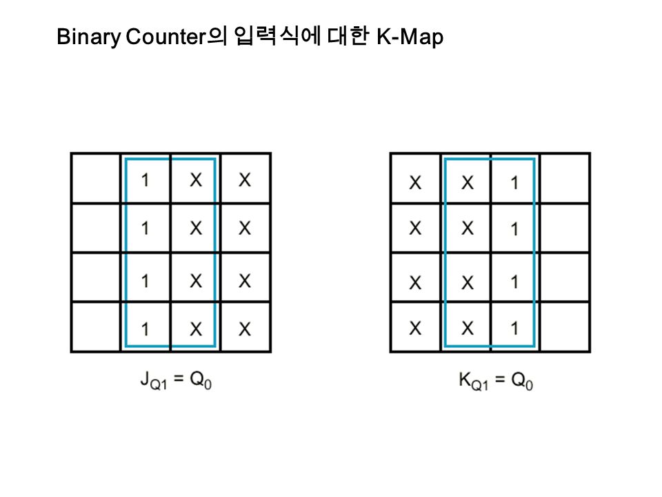
Binary Counter 의 입력식에 대한 K-Map

17
4-Bit synchronous Binary Counter - EN : Count enable input - J Q0 = K Q0 = EN J Q1 = K Q1 = Q 0 · EN J Q2 = K Q2 = Q 0 · Q 1 · EN J Q3 = K Q3 = Q 0 · Q 1 · Q 2 · EN 일반적으로 표기하면 다음과 같다 J Qi = K Qi = Q 0 · Q 1 · Q 2 ·...Q i-1 · EN

18
D-F/F 을 이용한 4-Bit Binary Counter Flip-Flop Inputs D Q3 D Q2 D Q1 D Q0

19
D-F/F 을 이용한 4-Bit Binary Counter ( 계속 ) 00 01 11 10 00 01 11 10
")
20
D-F/F 을 이용한 4-Bit Binary Counter ( 계속 ) 00 01 11 10 00 01 11 10
")
21
D-F/F 을 이용한 4-Bit Binary Counter ( 계속 ) 00 01 11 10 00 01 11 10
")
22
D-F/F 을 이용한 4-Bit Binary Counter ( 계속 ) 00 01 11 10 00 01 11 10
")
23
D-F/F 을 이용한 4-Bit Binary Counter D Q0 (Q 3,Q 2,Q 1,Q 0 ) = Σm(0,2,4,6,8,10,12,14) = Q 0 (XOR) EN D Q1 (Q 3,Q 2,Q 1,Q 0 ) = Σm(1,2,5,6,9,10,13,14) = Q 1 (XOR) (Q 0 ·EN) D Q2 (Q 3,Q 2,Q 1,Q 0 ) = Σm(3,4,5,6,11,12,13,14) = Q 2 (XOR) (Q 0 ·Q 1 ·EN) D Q3 (Q 3,Q 2,Q 1,Q 0 ) = Σm(7,8,9,10,11,12,13,14) = Q 3 (XOR) (Q 0 ·Q 1 ·Q 2 ·EN) 따라서 일반적인 D F/F 입력은 다음과 같이 쓸 수 있다. D Qi = Q i (XOR) (Q 0 ·Q 1 ·Q 2 ·...Q i-1 ·EN)
 (Q 0 ·Q 1 ·Q 2 ·...Q i-1 ·EN).")
24
D-F/F 을 이용한 4-Bit Binary Counter

25
Serial and Parallel Counters Serial counter ; Serial gating 을 가지고 있는 Carry logic 을 사용하는 counter. ; Fig.7-13 (a),(b) 의 점선 부분 비교할 것. Parallel counter : Fig.7-13 (b) 처럼 parallel gating 을 가진 counter. Parallel counter 의 장점 ; “1111” 에서 “0000” 으로 변할 때 오직 하나의 AND gate 에 의한 delay 가 있는 반면, serial 은 4 개의 AND gate 에 의한 delay 가 있다.
,(b) 의 점선 부분 비교할 것. Parallel counter : Fig.7-13 (b) 처럼 parallel gating 을 가진 counter. Parallel counter 의 장점 ; 1111 에서 0000 으로 변할 때 오직 하나의 AND gate 에 의한 delay 가 있는 반면, serial 은 4 개의 AND gate 에 의한 delay 가 있다..")
26
Serial and Parallel Counter (Fig.7-13) Serial Gating Parallel Gating
 Serial Gating Parallel Gating")
27
Up-Down Binary Counter - Down Counter ; LSB is complemented with each clock pulse. ; A bit in any other position is complemented if all lower significant bits are equal to "0". ex) 0100 →0011 -Up counter 회로와의 차이점 ; AND gate 의 입력을 각 F/F 의 complemented 된 출력이 연결된다.
 0100 →0011 -Up counter 회로와의 차이점 ; AND gate 의 입력을 각 F/F 의 complemented 된 출력이 연결된다..")
29
Up-Down Binary Counter - Up-Down Binary Counter 의 설계 ; Needs Mode input S to select between the two operations. ; S=0 for down counting, S=1 for up counting ; EN=1 for normal counting operation EN=0 for disabling both counting

30
Up-Down Binary Counter ( 계속 ) T A0 = EN T A1 = Q 0 · S · EN + Q 0 · S · EN T A2 = Q 0 · Q 1 · S · EN + Q 0 · Q 1 · S · EN T A3 = Q 0 · Q 1 · Q 2 · S · EN + Q 0 · Q 1 · Q 2 · S · EN Carry outputs for the next stages C up = Q 0 ·Q 1 ·Q 2 ·Q 3 · S · EN C down = Q 0 ·Q 1 ·Q 2 ·Q 3 · S · EN
 T A0 = EN T A1 = Q 0 · S · EN + Q 0 · S · EN T A2 = Q 0 · Q 1 · S · EN + Q 0 · Q 1 · S · EN T A3 = Q 0 · Q 1 · Q 2 · S · EN + Q 0 · Q 1 · Q 2 · S · EN Carry outputs for the next stages C up = Q 0 ·Q 1 ·Q 2 ·Q 3 · S · EN C down = Q 0 ·Q 1 ·Q 2 ·Q 3 · S · EN")
31
Binary Counter with Parallel Load - Initial binary number into the counter prior to the count operation. ; CO (carry out) is useful for expanding the counter to more stages. - Counters with the parallel load are very useful in the design of digital computer. 이것은 register with load and increment operation. - Increment 란 register 의 내용에 “1” 을 더하는 것. By enabling the count input during one clock period, the content of the register can be incremented by one. Function Table for Fig.7-14 Load Count Operation 0 0 No Change 0 1 Count next binary state 1 X Load Input
 is useful for expanding the counter to more stages. - Counters with the parallel load are very useful in the design of digital computer. 이것은 register with load and increment operation. - Increment 란 register 의 내용에 1 을 더하는 것. By enabling the count input during one clock period, the content of the register can be incremented by one. Function Table for Fig.7-14 Load Count Operation 0 0 No Change 0 1 Count next binary state 1 X Load Input.")
32
4-Bit Binary Counter with Parallel Load (Fig.7-14)
")
33
BCD counter Binary counter with parallel load 로 구성 (Fig.7-15)
")
34
BCD Counter 설계

35
BCD Counter 계속 D-F/F 을 사용하여 카운터 설계 각 F/F 의 입력식 D1 = D2 = D4 = D8 = Y =

36
임의의 순서를 갖는 Counter

Similar presentations


 the number of times a particular event or process has occurred, often in relationship.>")


